Close
0%
0%

Communication Board For People With Disabilities

we are making a playground communication board to help people with disabilities

Similar projects worth following
we are making a playground communication board to help people with disabilities

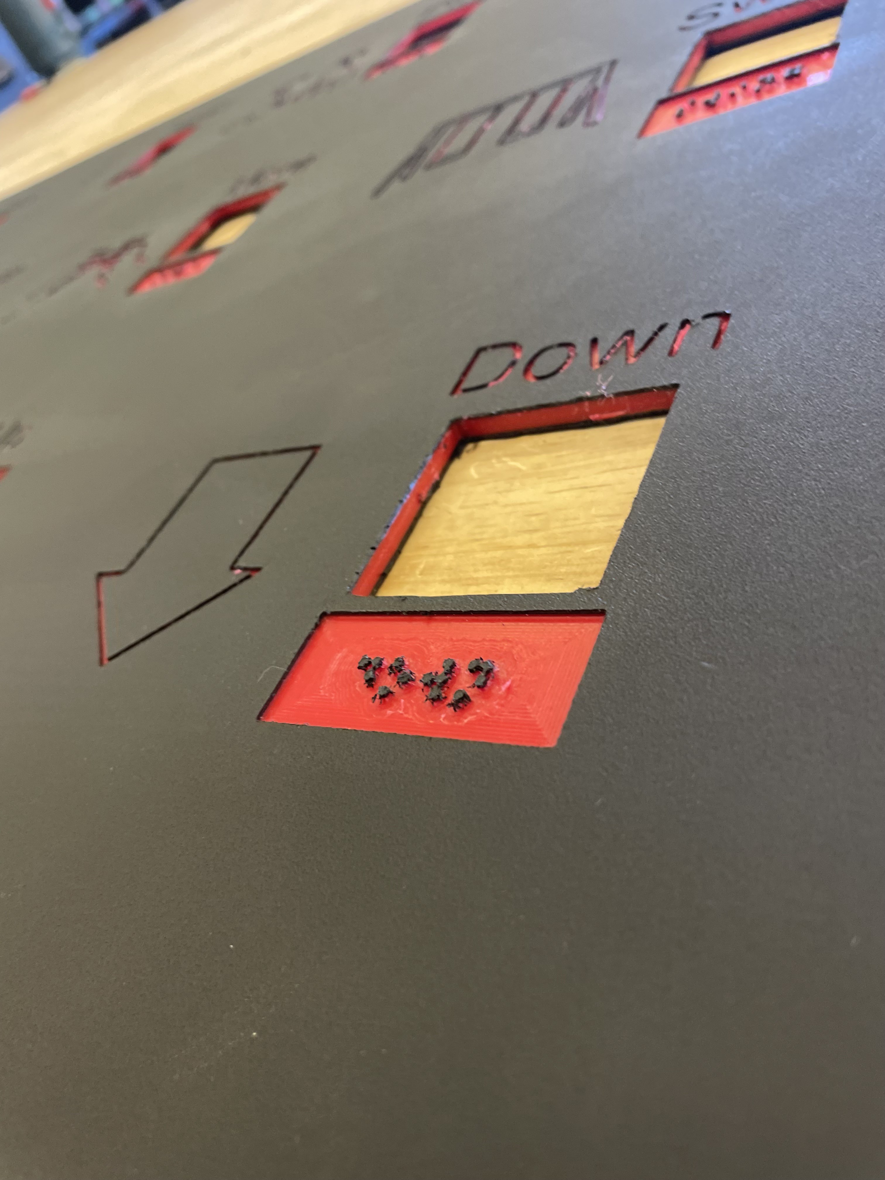
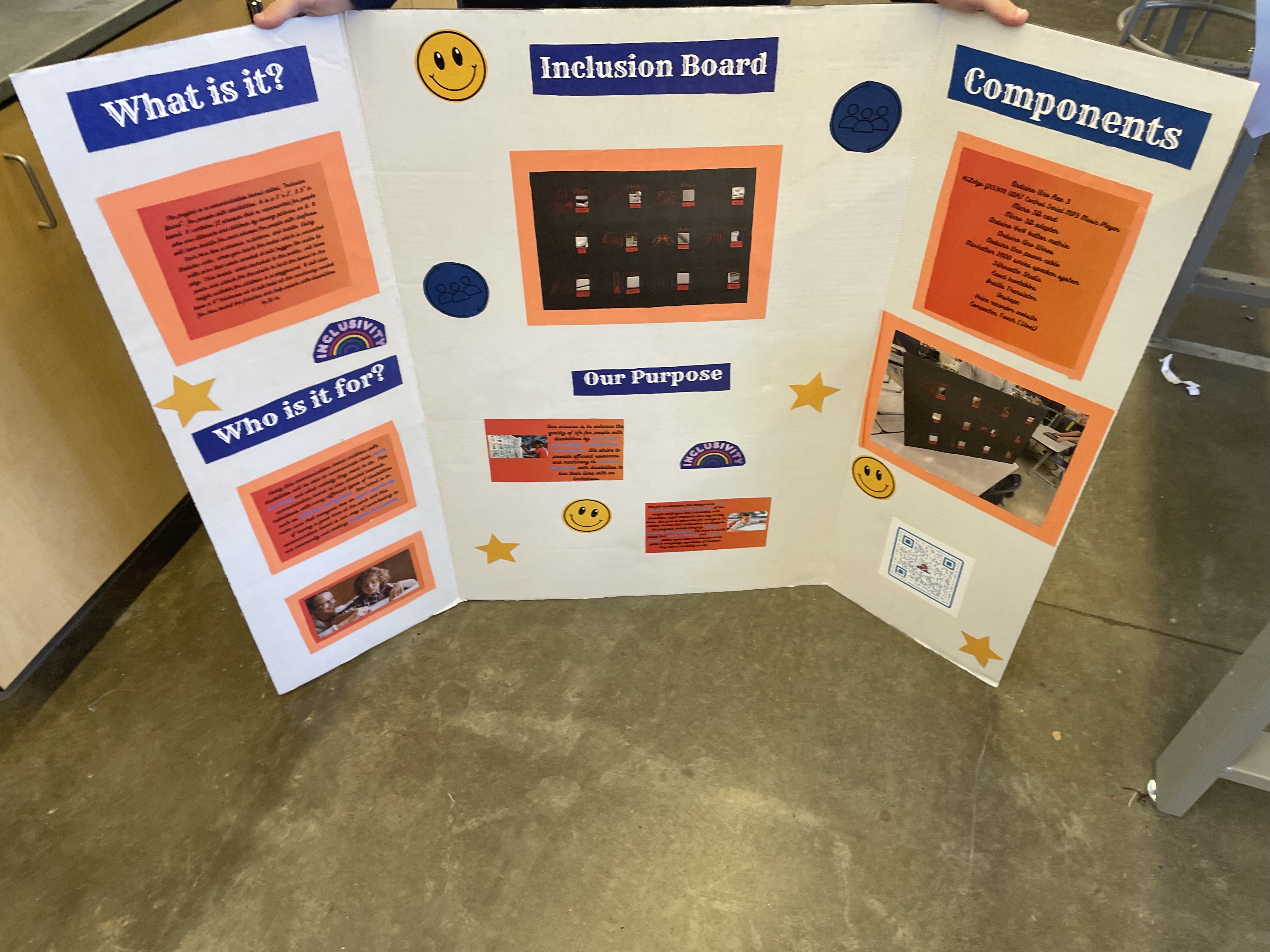
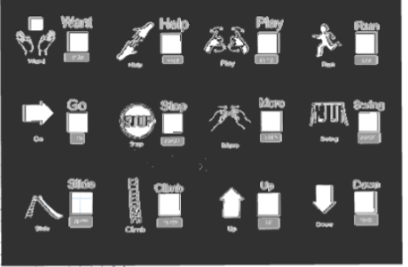
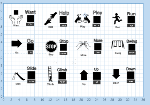
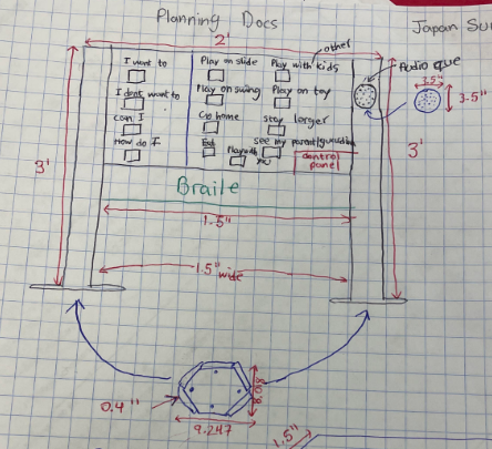
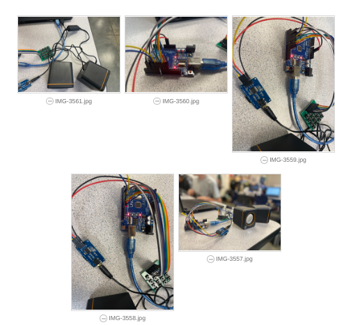
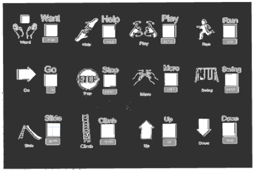
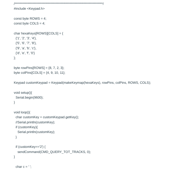
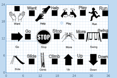
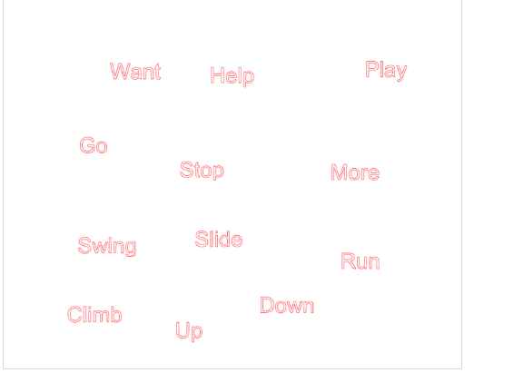
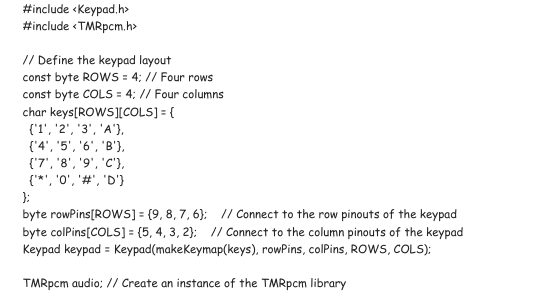
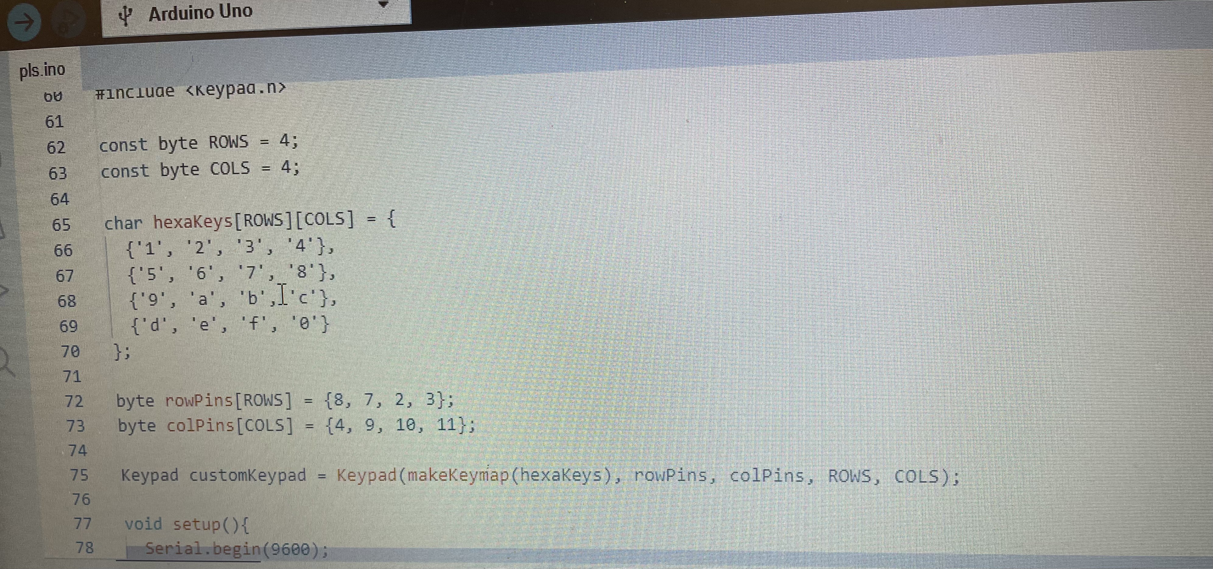
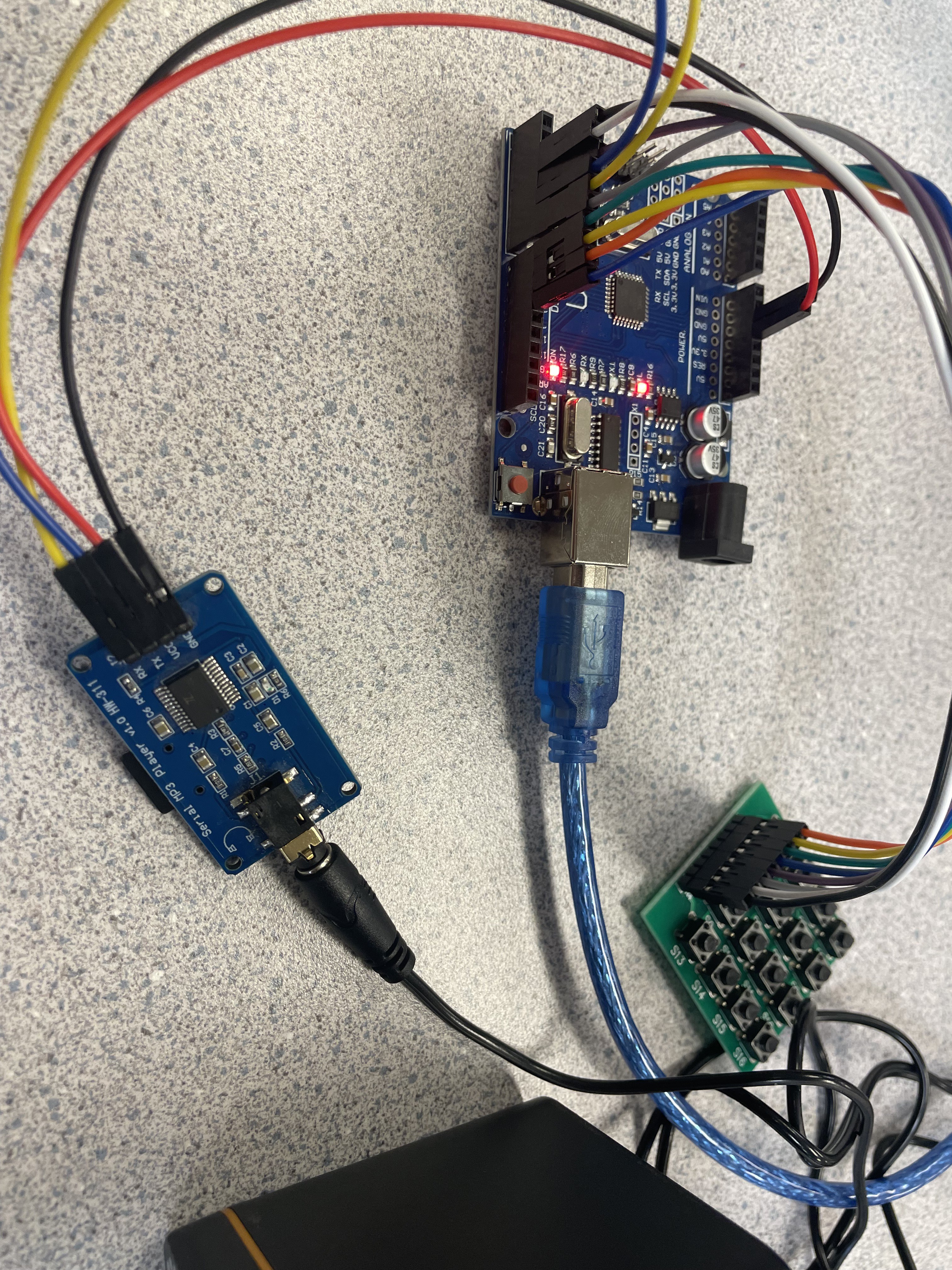
The target of this project is to create a communication board that could be used meant to be placed in playgrounds. This project was a multi-week process consisting of thorough planning on each individual piece of our communication board. We used different tools such as 3d design software to plan our board and imprint the braille, Arduino to code our voice command system, and photo editing software to add pictures to our board for individuals who might have a tougher time reading words. Using this communication board children with disabilities will be able to communicate their wants and needs and what activity they want to do. This communication board is also directed towards individuals with many different types of disabilities such as blindness and dyslexia. Our intent is to make sure that everyone has an equal opportunity of having a good time at the park and this communication board is our way of contributing to our community and making everyone feel included. 

Screenshot 2023-05-19 11.49.34 AM.png

showing that the board is 3d

Portable Network Graphics (PNG) - 86.68 kB - 05/19/2023 at 18:49

Preview
Download

Screenshot 2023-05-18 11.04.27 AM.png

Finished CAD of our board

Portable Network Graphics (PNG) - 69.90 kB - 05/18/2023 at 18:15

Preview
Download

JPEG Image - 4.46 MB - 05/18/2023 at 05:23

Preview
Download

JPEG Image - 5.06 MB - 05/18/2023 at 05:23

Preview
Download

JPEG Image - 4.29 MB - 05/18/2023 at 05:21

Preview
Download

View all 8 files

View all 14 components

  • Week of May 29th

    bhattacharyaa06/05/2023 at 21:51 0 comments

    We did not have school on Monday. 

    -On Tuesday, our team gathered together to kickstart the brainstorming session for our trifold project. We aimed to generate creative ideas and concepts that would effectively convey our message and captivate our target audience. Kasen and Rishi worked on planning out the different elements that went into our board. That exact day Kasen printed out all of the pictures and decorations while Rishi worked on writing out the components and other text. While they were doing this Arnav made the script that would help us remember everything that we needed to talk about. 

    -On Wednesday, using a tin snip we cut out the steel for our buttons and taped it onto the back of the board. We also made a script for our presentation that would convey our message to our audience so that we would have a script that told us all of the information we needed to cover in our presentation. While Rishi and Kasen were measuring out the boxes on the piece of tin and cutting them out individually. Arnav was finalizing the code and there seem to have appeared an error with the curly braces and Arnav fixed it. Kasen also worked on sanding the edges for the squares. 

    That evening we presented our presentation to the judges. 

    OUR PROJECT WAS FINISHED!!!

    -On Thursday and Friday we were finished with our presentation and didn't work on it those two days. 

  • Week of May 22nd

    Rishi06/05/2023 at 18:46 1 comment

    Japan Surge: Week of 5/22 Hackaday Log By: Rishi, Arnav, and Kasen

    Monday:

    Arnav:

     Worked on the code to make buttons work on the 4x4 matrix. Arnav was able to figure out the code and the problem seemed to be that the buffers were not in tune with the ports and this meant that the files from the sd card were not properly pairing with the arduino uno thus causing a blockage between the arduino uno and the sd card. Once the buffers were in tune with the ports on the arduino uno, audio was successfully playing out of the speakers. We had to watch multiple different youtube videos to come to our solution on how to link up the buffers with the speaker outputs. 

    Kasen:

    Our project was due the very next week so Kasen checked Basecamp, Hackaday, code, and project resources for any missed information. He went through the rubric multiple times to make sure that all components of our project were functional and wouldn’t have any last second errors that we had to stress about. Kasen noticed that our basecamp entries for our project were a bit unorganized so he spent the rest of the class period organizing our basecamp entries into their respective sections so we were ready to present it. 

    (Have finished all the logs thanks to Kasen:)

    Rishi:

    On Monday Rishi got to school a bit early so that he could work on tracing our board in silhouette studio. This took multiple attempts because the braille wouldn’t trace correctly as it was a small dot but the problem was that Rishi was tracing in a relatively small font which would cross over with the other components of the board. Rishi increased the size of the braille which gave him a bigger field of view and allowed him to be more precise with the dots that he was making. The braille translator that we used was often giving us the wrong braille translations however the website was sometimes giving us the wrong output so we used a different braille translator which gave us the correct output. We linked the correct braille translator in our hackaday components. He then continued working on the easel inventables. Rishi had shown Mr. Woodbridge but the teacher had given him very helpful feedback that made the board turn out really well.

    Link for amazing braille translator:translator:https://wecapable.com/braille-translator/english-to-braille-converter/

    Tuesday:

    Arnav: Arnav had done the step by step design process. In this he had outlined what websites he used to start the code. He also described the code in great detail by showing where the 4x4 matrix occurred in the code and teaching how the code works. He is working on the code and got one button to properly function. Arnav finished up the build design process and updated our May 8th log so that it correlated with everything we did that week including finalizing the CAD as well as fixing up getting our project ready for presentation day.

    Kasen: Kasen had done the pictures on basecamp and hackaday. He had taken pictures of the machinery and the code. He also had finished organizing basecamp. He put in all the hackaday links for the project. He also put pictures of onshape, which is where we mapped out our idea of how the board will look like. Kasen also put the pictures for the updated draft dimensions for the playground communication board. However, as always there seems to be a problem showing up every day. Our wires had gotten unplugged in the box! Kasen carefully looked at our code and our pictures to rewire everything.

    Rishi: Rishi had done the step by step tutorial on how to construct a playground communication board on hackaday. He put detailed information and pictures on how to accomplish it. Rishi had also put the final touches on the mission statement and our purpose for this project. He also had finished the easel inventables and had corrected the feedback given by his teacher, Mr.Woodbridge.

    Wednesday:

    Arnav: On Wednesday, Arnav and Rishi learned from our teacher on how to correctly clamp down our board...

    Read more »

  • May 15th Log

    bhattacharyaa05/19/2023 at 19:18 0 comments

    Arnav: This week we worked on the code a bit more and the audio now successfully works. We made sure to list all of the commands so that now the project can function on the stroke of a few keys on the serial monitor. I also put all the links for the Hackaday in Basecamp

    Rishi: I put all the build procedures and code procedures into Basecamp and Hackaday. I added step-by-step detailed instructions on how to do all of the projects by yourself. I also started on easel inventable which is a software where you make your board that you later cut out using a CNC mill.

    Kasen: I took pictures of all the machinery. I also took screenshots of the CAD we did so we can so pictures in our step-by-step processes. I gave Rishi all the pictures so he can put them into the step-by-step procedures so people can follow along on the process

  • Final Code

    bhattacharyaa05/19/2023 at 04:55 1 comment

    #include <SoftwareSerial.h>
    #define ARDUINO_RX 5//should connect to TX of the Serial MP3 Player module
    #define ARDUINO_TX 6//connect to RX of the module
    SoftwareSerial mySerial(ARDUINO_RX, ARDUINO_TX);
    static int8_t Send_buf[8] = {0} ;

    #define CMD_SEL_DEV 0X09
    #define DEV_TF 0X02
    #define CMD_PLAY_W_VOL 0X22
    #define CMD_PLAY 0X0D
    #define CMD_PAUSE 0X0E
    #define CMD_PREVIOUS 0X02
    #define CMD_NEXT 0X01


    void setup()
    {
        mySerial.begin(9600);
              Serial.begin(9600);
          delay(500);//Wait chip initialization is complete
          sendCommand(CMD_SEL_DEV, DEV_TF);//select the TF card 
          delay(200);//wait for 200ms
          sendCommand(CMD_PLAY_W_VOL, 0X1E01);//play the first song with volume 30 class
    }
    String str;
    void loop() {
    if(Serial.available())
    {
    str = Serial.readStringUntil('\n');


    if(str == "2")
    {
    sendCommand(CMD_PLAY_W_VOL, 0X1E02);//play the second track with volume 30 class
    Serial.println("Second sound track.");
    }
    if(str == "3")
    {
    sendCommand(CMD_PLAY_W_VOL, 0X1E03);//play the third track with volume 30 class
    Serial.println("Third sound track.");
    }
    if(str == "4")
    {
    sendCommand(CMD_PLAY_W_VOL, 0X1E04);//play the forth track with volume 30 class
    Serial.println("Forth sound track.");
    }
    if(str == "ps")
    {
    sendCommand(CMD_PAUSE, 0X0E);//pause the playing track
    Serial.println("Pause");
    }
    if(str == "pl")
    {
    sendCommand(CMD_PLAY, 0X0D);//play it again
    Serial.println("Play");
    }
    if(str == "pr")
    {
    sendCommand(CMD_PREVIOUS, 0X02);//play previous track
    Serial.println("Playing previous track.");
    }
    if(str == "nx")
    {
    sendCommand(CMD_NEXT, 0X01);//play next track
    Serial.println("Playing next track.");
    }
     }
    }


    void sendCommand(int8_t command, int16_t dat)
    {
      delay(20);
      Send_buf[0] = 0x7e; //starting byte
      Send_buf[1] = 0xff; //version
      Send_buf[2] = 0x06; //the number of bytes of the command without starting byte and ending byte
      Send_buf[3] = command; //
      Send_buf[4] = 0x00;//0x00 = no feedback, 0x01 = feedback
      Send_buf[5] = (int8_t)(dat >> 8);//datah
      Send_buf[6] = (int8_t)(dat); //datal
      Send_buf[7] = 0xef; //ending byte
      for(uint8_t i=0; i<8; i++)//
      {
        mySerial.write(Send_buf[i]) ;
      }
    }

    __________________________________________________________________________

    Description of our code:

    *no specific libraries need to be downloaded for this code

    The first part of our code is just defining everything such as our commands and getting the code ready for execution. Then we get into the void setup which is setting the data rate of our serial monitor as well as initializing the external parts of the Arduino such as the chip. Then we get into the commands themselves. All of these commands are put into a loop so that the user can click and listen to the audio cue as many times as needed. Those strings are then used to play the audio once they are typed. Finally, the last part of our project is the buffers. Buffers are what you save your arrays of data on. These are basically acting as cabinets that are holding all of our two-dimensional data that the code is working based on. It takes the data on our Micro SD card and arranges it. 

    Mistakes to watch out for:

    A mistake that we realized that caused the speakers to not play the command was the Arduino RX and TX pins. Whilst connecting these please be careful that the RX on the serial mp3 player is connected to the TX on the Arduino Uno(whatever button you set it to for us the RX was hole 5 and the TX was hole 6 ). 

  • Step by Step Process of Communication Board Project

    Rishi05/18/2023 at 18:12 0 comments

    We first got the idea to make a communication board by inspiring people our teacher set up with this. First, we brainstormed how we could make the communication board. We first thought of an idea of two posts that are 3' x 1.5' x 1.5', a board that is 3' x 2' x 0.5' (we did 4' depth so we can do lining easier), and a base plate that is 9.247'' x 8.018'' x 0.4''. We started by mapping out what we had on our paper. We drew the designs shown below.


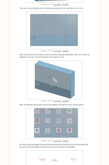
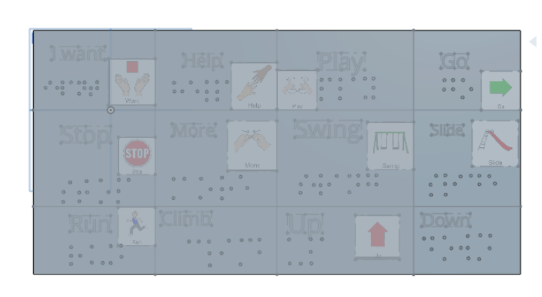
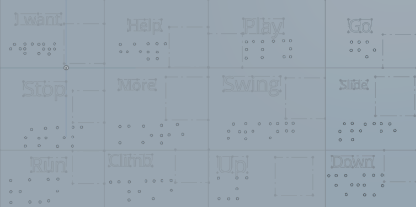
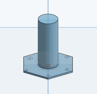
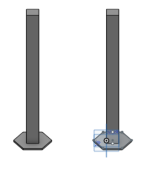
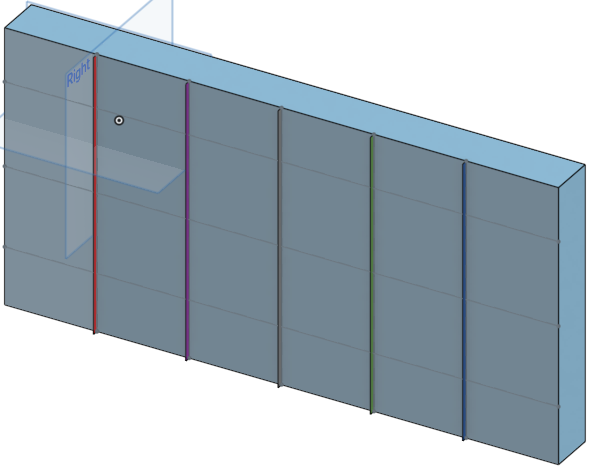
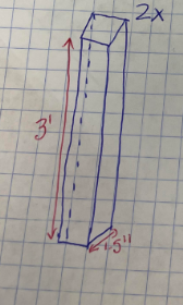
    Next, we put our ideas onto CADing software. We used onshape to CAD all our pieces. The link to using onshape and how it works is here:
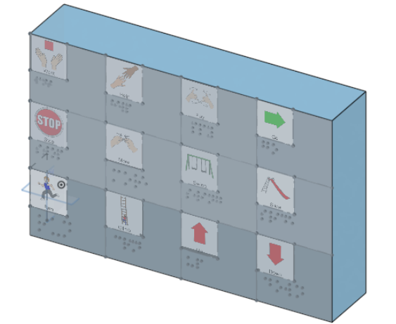
 https://osd.onshape.com/c/activity

    We put each box and braile to the top left side of board because it will look neat and professional. (We made the thickenss 4'' in this picture below because it was easier for us to do the lining.)

    After we had a solid idea of what we were doing we started coding. We coded arduino code. When you press a metal square, (that will be shown on the final project), the code will trigger that sound and it will play on the board through the speakers. We used machinery to do this code. 

     These are the machinery we used :

    Then we used software called Sillohete Studios, (https://www.silhouetteamerica.com/software), which allowed us to correctly trace our images, words, and braille to be able to put onto our Easel Inventables board We needed to trace because we cannot import pictures like that onto our board. We then sent our tracings to our teacher and he gave us back a sns file which allows us to import them onto board.

    We then started making our finalized board that will be printed using CNC milling.

    We started by gathering the correct pictures, words, and braille. We used the correct braille measurements set by the government so people with blindness can read it correctly. We placed each picture, word, and braille for 12 phrases on the board. We carved the braille using the square feature to push down the board around the braille. The finalized board is this:

    As shown above, we cut squares for the metal to go in. The metal is attached to a wire and when touched it will trigger the could and say the word that is shown to the left of the button. We then put words on top of the box to signify which box represents which word/picture.

    This is our project and we are very thankful for our teacher helping us throughout the journey of this project of making a playground communication board.

  • Week of May 8th

    Rishi05/16/2023 at 18:09 0 comments

    Monday through Wednesday we are working on the code.  We improved our button matrix and code.

    We got the CAD finished and ready to check. Our teacher made improvements and told us to do it on Easel Inventables and trace everything using Silhouette Studio. So on Thursday and Friday, we redid our board because our size was incorrect. The measurements now are 3' x 2' x 0.5'.

    Finished Product:

  • Week of May 1st

    Rishi05/02/2023 at 18:56 0 comments

    May 1st/2nd - Rishi started tracing all the pictures words and braille onto Shillouete studio. I downloaded all the tracing links and sent it to our teacher who sent us back the written format of the pictures, words, and braille that we started putting onto the easel inventable.

     Arnav: We have got a code outline of the code and we got one sound function to work. With the help of our amazing teacher, we wired up and tested the 4x4 matrix code and it worked very well. But some wires are not responding and we think it is due to our not fully understanding how to code the numbers with columns and rows. 

    Kasen: CAD is basically done just some minor tweaks. Now we need to design how we will attach each piece to another or put all the parts into one piece. Also, we implemented braille onto our communication board so blind people can feel what's being said on the board and click it.


  • Week of April 24th

    Rishi04/17/2023 at 18:34 0 comments

    Rishi: We started working on the base plates We are making base plates so the posts can stand upright without falling. The width of the base plate is 9.247" and the length is 8.018" and the height is 0.4"  I also started learning how to use silhouette studio to trace our pictures, braille, and words onto our board. I also finished the missions statement and added all the cards to the card table so we have a good idea of what we need to get done to finish this project.

    This is the website to download and use silhouette studio: https://www.silhouetteamerica.com/software

    Kasen: I started learning braille. I watched tutorials and spent most of this week mastering the art of braille. I started on the base camp by adding pictures of our machinery and adding pictures of the dimensions of our board.

    Arnav: I started on the code. I used various websites to get the base code in. I am trying to code a 4x4 matrix so that when you click on a button it will trigger the code to make audio release from the speakers that are connected.

    This is the website I used: https://www.circuitbasics.com/how-to-set-up-a-keypad-on-an-arduino/

  • Week of April 17th

    Rishi04/17/2023 at 18:18 0 comments

    Kasen Rishi:

     We started mapping out everything we will do for the CAD (Only mapped out 2 this week): We planned the CAD by drawing out the sign on a piece of paper and we implemented that drawing into the CAD. We decided that the length of the board should be 1.5' and the width of the board should be 3". The height of the board should be 1'. The individual blocks should have a length of 2.25', a width of 3', and a depth of 1.5'.

    We started making posts and the board that will be connected towards the top of it. The length of the posts will be 3' length, the width of the post is 1.5' and the depth is 1.5'.


    Arnav: I started working on the code. I learned what code we need to use and started looking at tutorials. I learned a lot about Arduino code and how it works. I also connected all the machinery and discussed how everything worked. 

    This is the base video arnav used this week to understand the concept of Arduino: 


  • CAD Design: Board

    Rishi04/17/2023 at 18:07 0 comments

    We planned the CAD by drawing out the sign on a piece of paper and we implemented that drawing into the CAD.

    The length of the board should be 1.5' and the width of the board should be 3". The height of the board should be 1'.

    The individual blocks have a length of 2.25', width of 3' and a depth of 1.5'.

View all 10 project logs

  • 1
    Build Process(board)

    We first CADed a 3' x 2', 0.5'' rectangle (the depth was 4" because it was easier to do lining)

    Zoom image.png
    image.png 51.1 KB View full-size Download

    Then we cut up the big box into 12 little boxes using the line tool. Each box is 8 in x 9 in

    Zoom image.png
    image.png 15.5 KB View full-size Download

    Next, we hollowed out the inside so we can fit all the equipment (speakers, wires, etc.) inside. we hollowed it out until 1 inch; the thickness of the walls is 1 inch.

    Zoom image.png
    image.png 66.1 KB View full-size Download

    Next, we imported and put all 12 pictures with labels in the top left corner of each square.

    Zoom image.png
    image.png 50.2 KB View full-size Download

    All of this is just the design of what we want the board to look like. But now is the real thing. We first got to Silhouette Studio and traced the picture, the words, and the braille.

    Zoom Screen Shot 2023-05-15 at 10.52.38 PM.png
    Screen Shot 2023-05-15 at 10.52.38 PM.png 78.4 KB View full-size Download

    Then, on Easel Inventables, we made a board that was 3' x 2' x 0.5'. We then imported the sns files our teacher gave us after giving him the final tracings from silhouette studio. After that, we aligned everything on the board. Then we cut out holes using the shape feature for the metal touch activation and the wire.

    Zoom image.png
    image.png 73.4 KB View full-size Download

    Then we carved braille onto easel inventables. I used the national sizes for each word so it will be readable for people with blindness.


    Zoom image.png
    image.png 77.7 KB View full-size Download


    New boost

  • 2
    Build Process(Arduino Machinery)

    This is how you should put together your Arduino machinery. 

    1. Insert your SD card into your serial mp3 player. 

    2. Insert your 3.5 mm headphone jack into the correct port onto the mp3 player. 

    3. Next connect four wires to the other side of the serial mp3 player. 

               a. Important Wiring information: Make sure that the VCC on the serial mp3 player is                                 connected to 5V on the Arduino Uno. And the GND on the serial mp3 player is                                   connected to the nearest GND right next to the 5V on the Arduino Uno. The wires for the                 button matrix can be plugged into any key except 0 and 1(they just need to be calibrated                   in the program).

    4. Now that all of the tough wiring is done. Plug the blue Arduino power cable into the grey metal box on the Arduino and plug it into any port on the computer. 

    5. Plug the speaker power cable into the computer as well. 

    Now you are all set up with the machinery. For further instructions on the code please go to our log made specifically for the code in the log section of our project. 

  • 3
    Recording your commands

    Here are the instructions on how to record your commands: 


    1. First you will need to record your voice as an mp3 file. This can be done with free software which I will link right here. https://online-voice-recorder.com/

    2. Next you will save your audio and then drag it from your files section to paste it onto your dashboard. 

    3. Take out your sd card from your serial mp3 player and place it in the sd card adapter. 

    4. Plug the adapter into your computer and you should see the adapter pop up in your files. 

    5. At this point rename your files to 001.mp3, 002.mp3, 003.mp3, etc. This will make it much easier for organization purposes. 

    6. Drag the files from the dashboard into the sd card file. 

    7. After you have all the files in your sd card, you can eject the sd card. 

    8. Take out the adapter and the sd card that is in it. 

    9. Plug the sd card back into the serial mp3 player. 

    Now you should be ready to go with all of your files installed into the sd card. 

View all 3 instructions

Enjoy this project?

Share

Discussions

Similar Projects

Does this project spark your interest?

Become a member to follow this project and never miss any updates