 NNNI
NNNIIn my case, it was sadly not outer-space type music (Whoooooo!), but the slope scaler amplifier ringing.

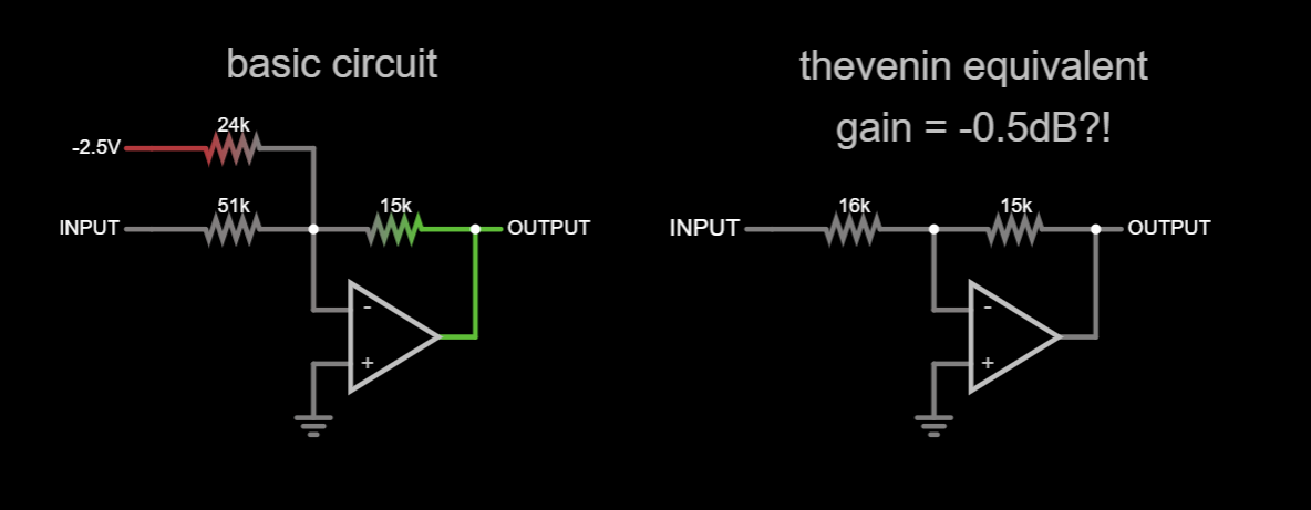
The slope scaler amplifier scales the +/-5V integrator swing to a reasonable 0V to 3V that the residue ADC can digitize. However, even early on, I noticed that the scaler amp had a slight ring to it. I naively dismissed this, since "it's meant to be a DC amplifier anyway". This is potentially a problem, since the output could ring with a sudden load change, like when the residue ADC is sampling.
The simple fix would be to just add a capacitor across R47 and call it done. The value of said capacitor is key - too little won't fix the problem, and too much would just slow the op-amp down unnecessarily. The key is to find the right value.
Instead of my preferred method of trying different capacitor values, I tried to take a more analytical approach. The first step in doing that would be to determine the gain of the scaler amp. This sounds like an easy task, since it is basically an inverting configuration. The problem starts when you realize that the gain is less than one, since R47 is 15K and R44 and R45 in parallel (since they both return to a low impedance node) come out to 16K. How does a circuit with a gain of less than one oscillate?!
The trick (kindly provided by a friend) here is to use something called the noise gain, which emulates input noise by connecting a voltage source in series with the op-amp's input terminals, changing it and seeing how the output changes. The output change for a given input change is the noise gain. This works regardless of the test source polarity or which input it is connected to.
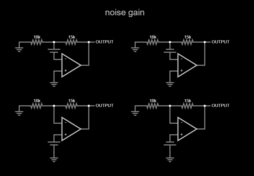
All of the above circuits are basically the classic non-inverting configuration with a gain of:
Thanks to the 1 term, the gain is always above (or at least equal to) 1, which makes a lot more sense from the ringing point of view. The noise gain is now 5.7dB. I employed LTspice to handle the mathematical heavy lifting from this point on.
I was able to find a model for the OPA197 (and verify it by doing a simple frequency response plot and seeing if it corresponded with the one in the datasheet) and simulate the above circuit.

The peaking in the frequency response before the gain rolls of below zero is a classic indicator for ringing.
I simulated the entire circuit, and to get the same ringing as I did in real life I had to add 25pF of capacitance to the summing junction node.

Now to the actual task of compensating it. I'm too embarrassed to reveal my own formula for a rough estimate, but it delivered 24pF, which was a little too much. 10pF worked perfectly.

After soldering a 10pF capacitor across R47, the results looked like this.

I found it highly amusing to see that theory and practice corresponded so perfectly for once.
Regarding the 25pF at the summing junction - the value seems suspiciously high to me. I can only assume that the same poor layout that messed with the residue ADC either created some extra capacitance at the summing junction or some stray inductance. Regardless, the ringing is now gone.
Apollo 10's space music turned out to be interference, by the way.
Discussions
Become a Hackaday.io Member
Create an account to leave a comment. Already have an account? Log In.