 Ted Fried
I am using a Digilent Arty Z7-20 SOC FPGA development board which contains a 600 Mhz ARM processor and has access to 500 MB of DRAM.
The FPGA core contains a 720-bit wide dual-ported RAM and a small state machine to fetch each display row and generate the MDA display timing.
Images are held in an array in the C code running on the ARM core which is then copied down to the dual-ported RAM in the FPGA code. This makes it easier to reload new images rather than storing the images in the FPGA core’s configuration bitstream.
The image array holds the full 720×350 bit image with one bit per pixel . It is generated by using GIMP to convert the original JPEG image to the appropriate size and color, then save as a BMP image. This image file is then converted to an array using a small C program I wrote.
I made this small cable to connect the MDA signals to the FPGA’s PMOD connector inputs.
This setup also worked on my amber MDA display.

 Peter Noyes
 Andrew Kadis
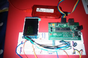
 Tahmid
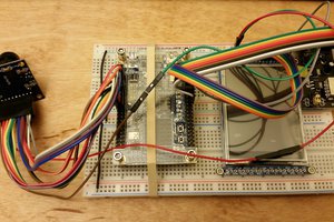
 Joshua Vasquez
Any future plans? I have an MDA monitor (went to a Brother word processor), well-stored but I have nothing to connect to it (and no room for an old 80's ISA based PC).
Are there "inputs" on this device, so (say) a Pi Pico or Raspberry Pi could TTL over the next set of images, making this act like a peripheral?