 Fulvio
We spent quite a bit of time designing the circuit that will allow the panel to move with the movement of the sun.
Let's remember the fundamental points of this project:
- minimal hardware, low cost
- self-tracker device, without GPS or WIFI
To fulfill this promise, we have come to realize this circuit:
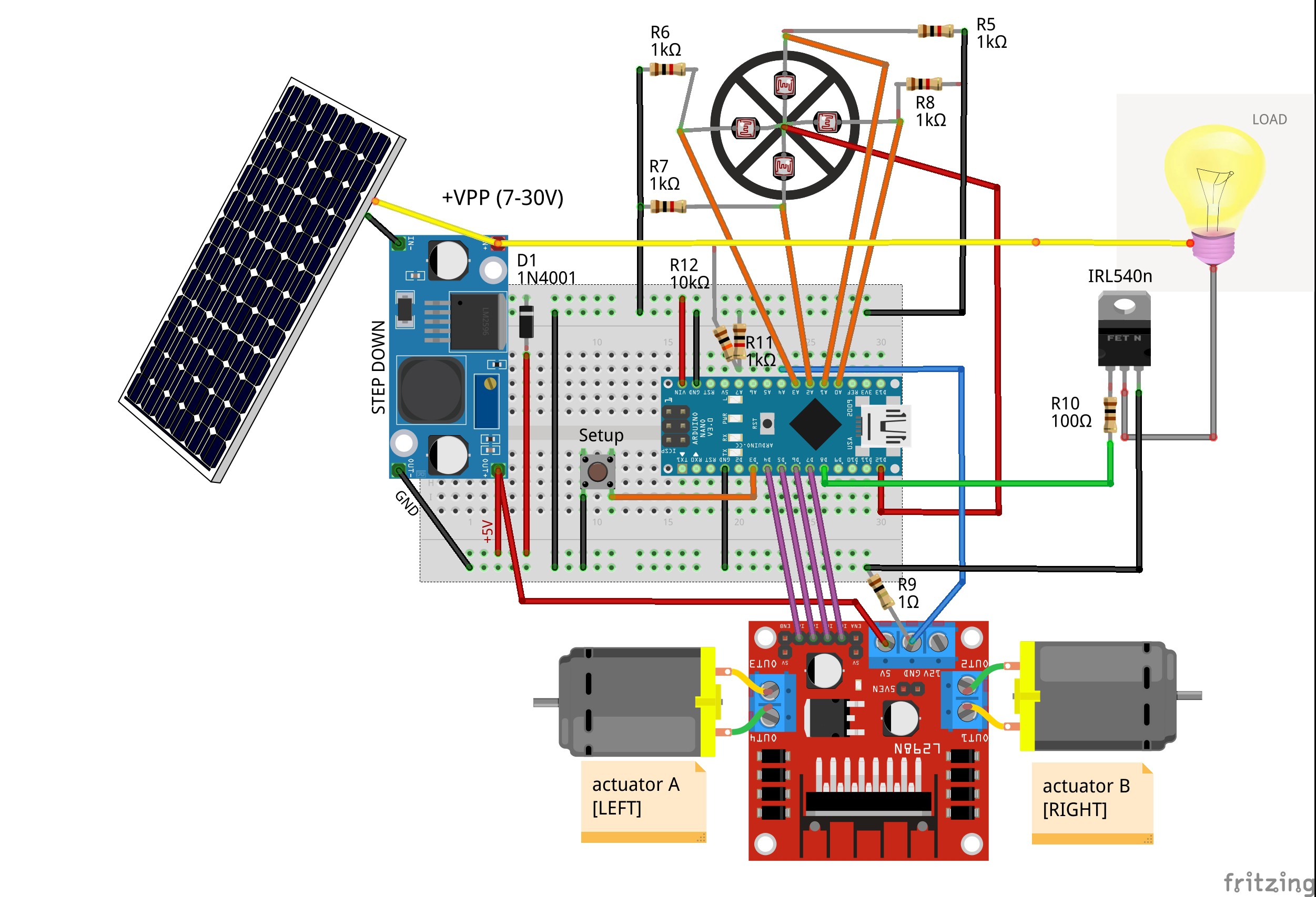
As you can see, we tried to use easy to find components and a handful of passive components.
Let's see the features together:
- CPU: we use a Arduino Nano as "brain" of mysoltrk. Low cost, low consuption and powerful enough for our project
- The board is powered by a step down, which reduces the voltage of the solar panel to 5V. Since there are so many step down, we picked one that delivers enough amps for the motors
- L298N: used to decouple the logic gates of the Arduino from the motors
- Photoresistors: with a simple divider we can interface the photoresistors to the Arduino
- IRL540n: used as a relay
- 1N4001 to protect Arduino when it is powered via USB and via solar panel at the same time
- We add a setup button, it will be useful in the future
There are some interesting points to note:
R9 Shunt resistor
We use shunt resistor to check the work of actuators.
Since our 3D printed actuators doesn't include limits switches, measuring the shunt value we can deduce this condition.
R11/R12 voltage divider
With this simple trick we can evaluate if the panel delivers enough energy to drive the actuator.
The calculation should be simple: read the value before and after running a motor.
IRL540n
Depending on the type/size of the solar panel, the power may not be enough to drive motors and external load at the same time, so we decided that the load should be controlled by mysoltrk.
For example, if there is not enough light, we can decide to use the panel's energy to drive actuators or to charge.
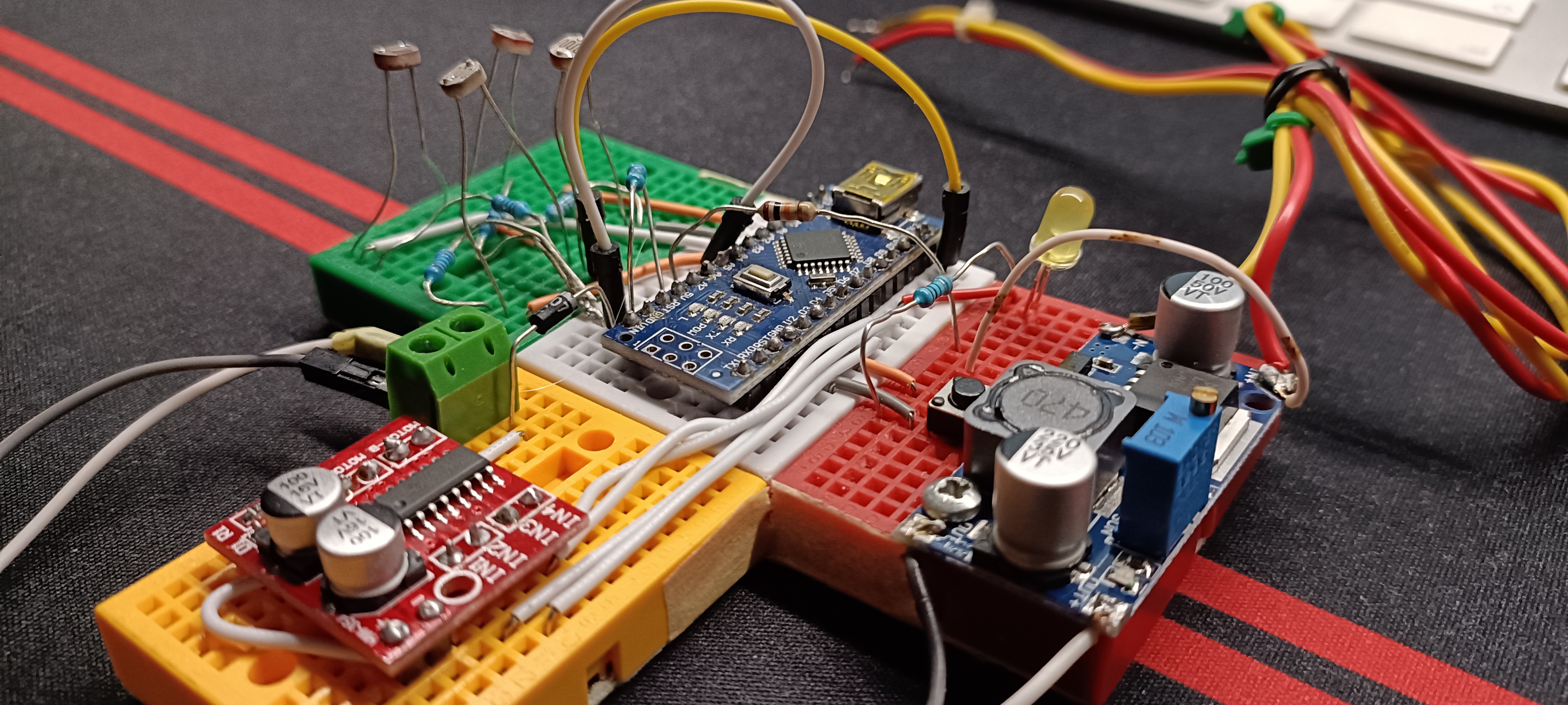
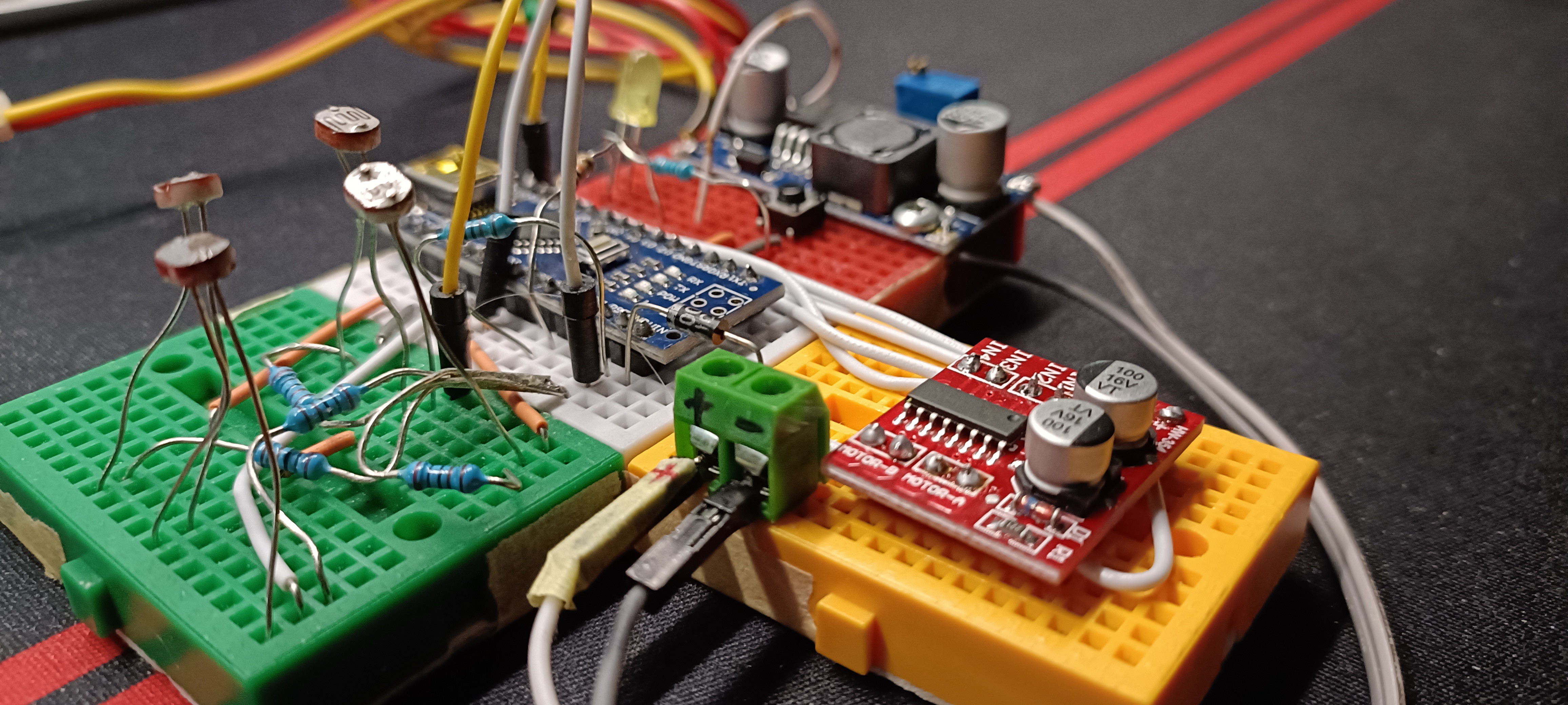
Before designing a printed circuit board, we want to try it with a breadboard in order to verify the correctness of the starting hypotheses:
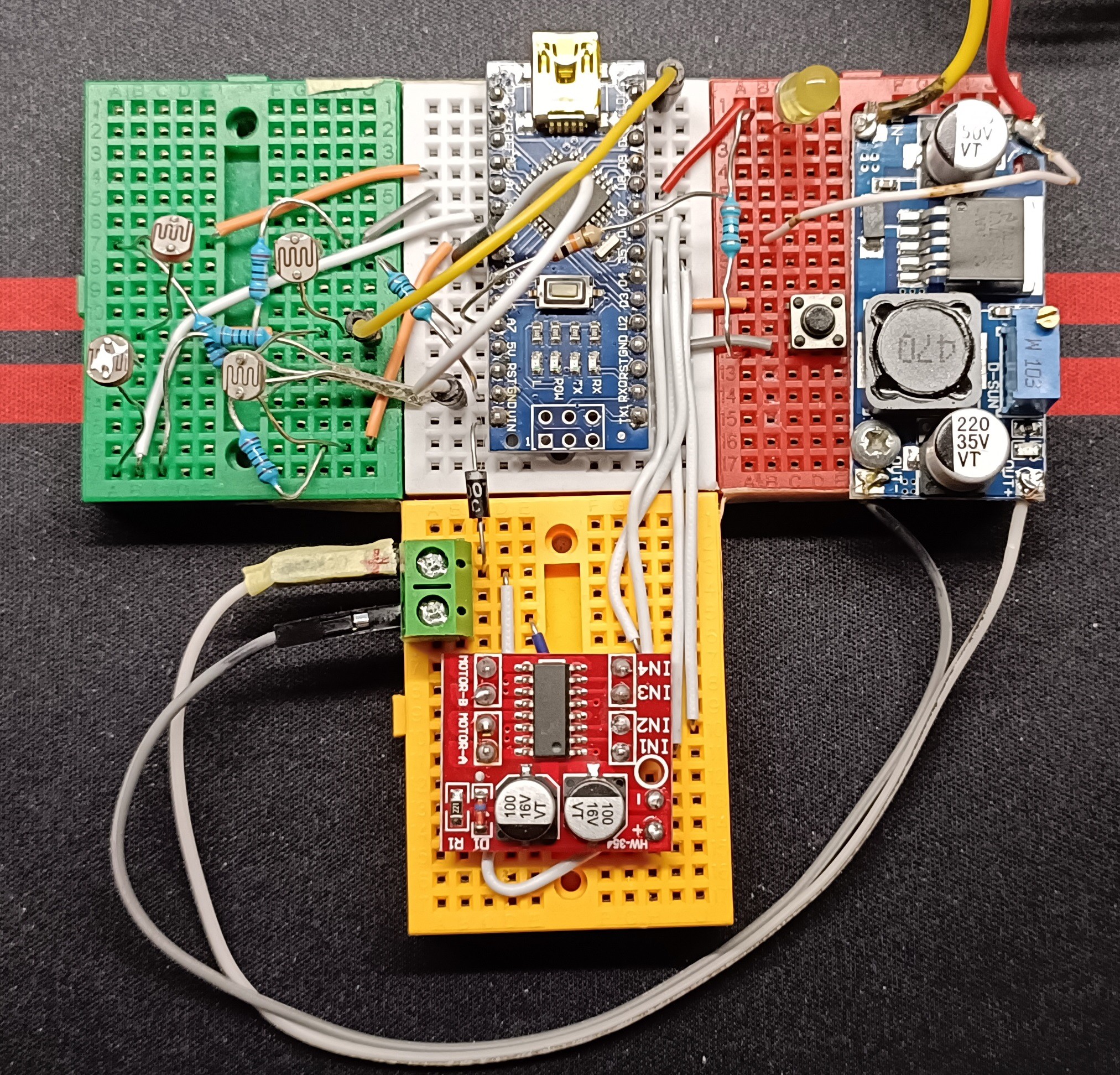
Note: in this photo the shunt resistor is missing (a late order)
Now we can start to write code to test actuators and photoresistors.
Discussions
Become a Hackaday.io Member
Create an account to leave a comment. Already have an account? Log In.