 M. Bindhammer
Introduction
A cyborg is a living being that has been technically supplemented or enhanced. It is thus a manifestation of human enhancement. This serves the increase human possibilities and increases human efficiency and thus the improvement and optimization of humans. Furthermore, by my own definition, a cyborg must have at least one bio-feedback in both directions that provides the cyborg with a superhuman ability. I have chosen the head and thus a mask because most senses are located in the head and almost all important biomedical parameters can be measured at the head. Secondly, man has been using masks since the beginning of mankind. The oldest mask found is about 11,000 years old and comes from Israel. Remains of stone or metal masks were found - but drawings show that less durable materials such as cloth, plants, feathers, leather, or papyrus were also used to make masks. Masks are worn for very different reasons. For example, in the days before plastic surgery, masks were the best solution for veterans with faces scarred by war. And last but not least, almost every superhero or superheroine wears a mask.
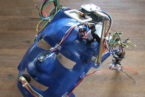
Design starting point
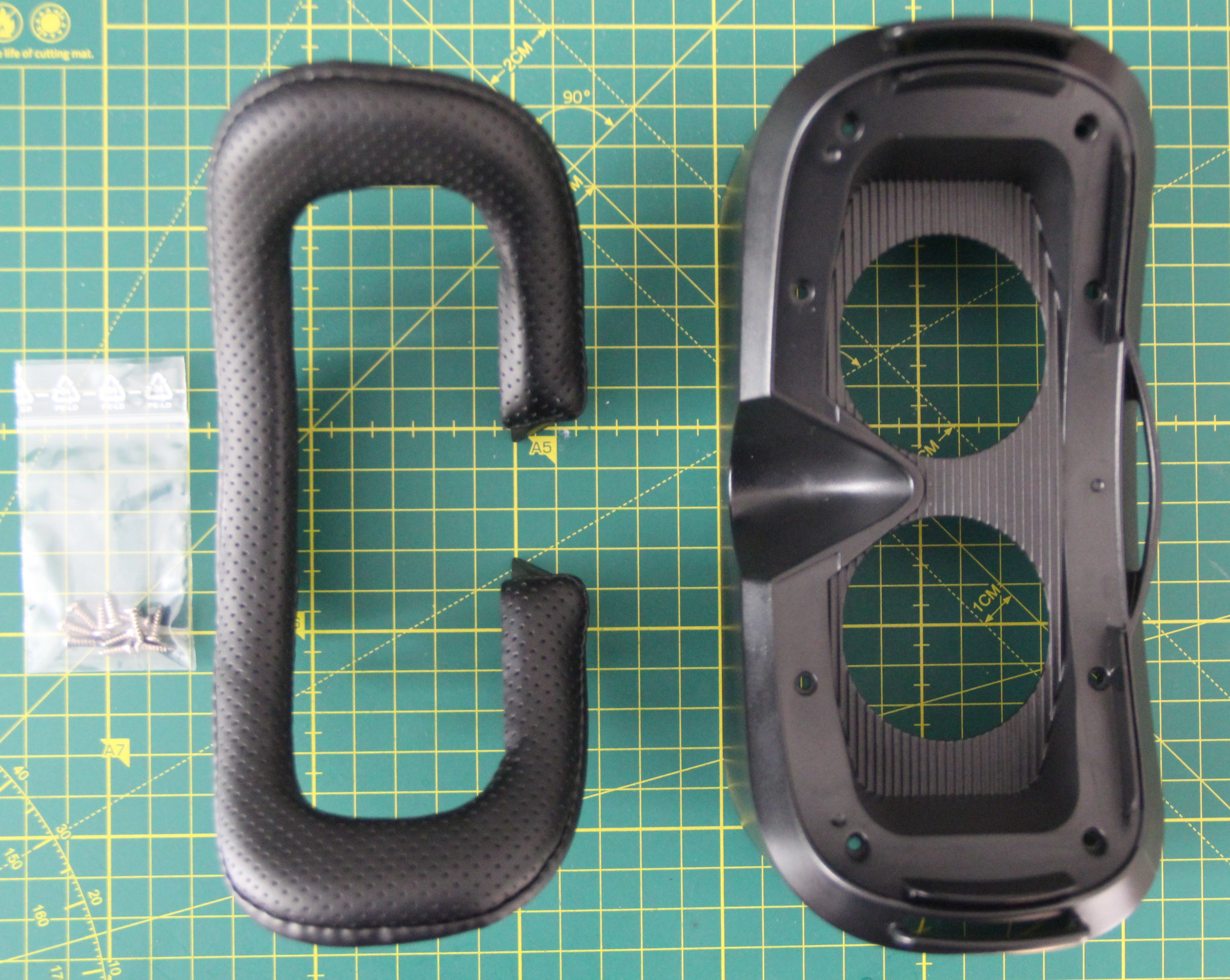
To avoid complex design and high 3D printing costs, I decided to use smartphone VR glasses as the starting point of the design. These are cheap, mostly made of ABS, and therefore easy to modify. First, I removed the optics and all unnecessary parts. I will salvage parts of the optics later.
The mask could look something like that:
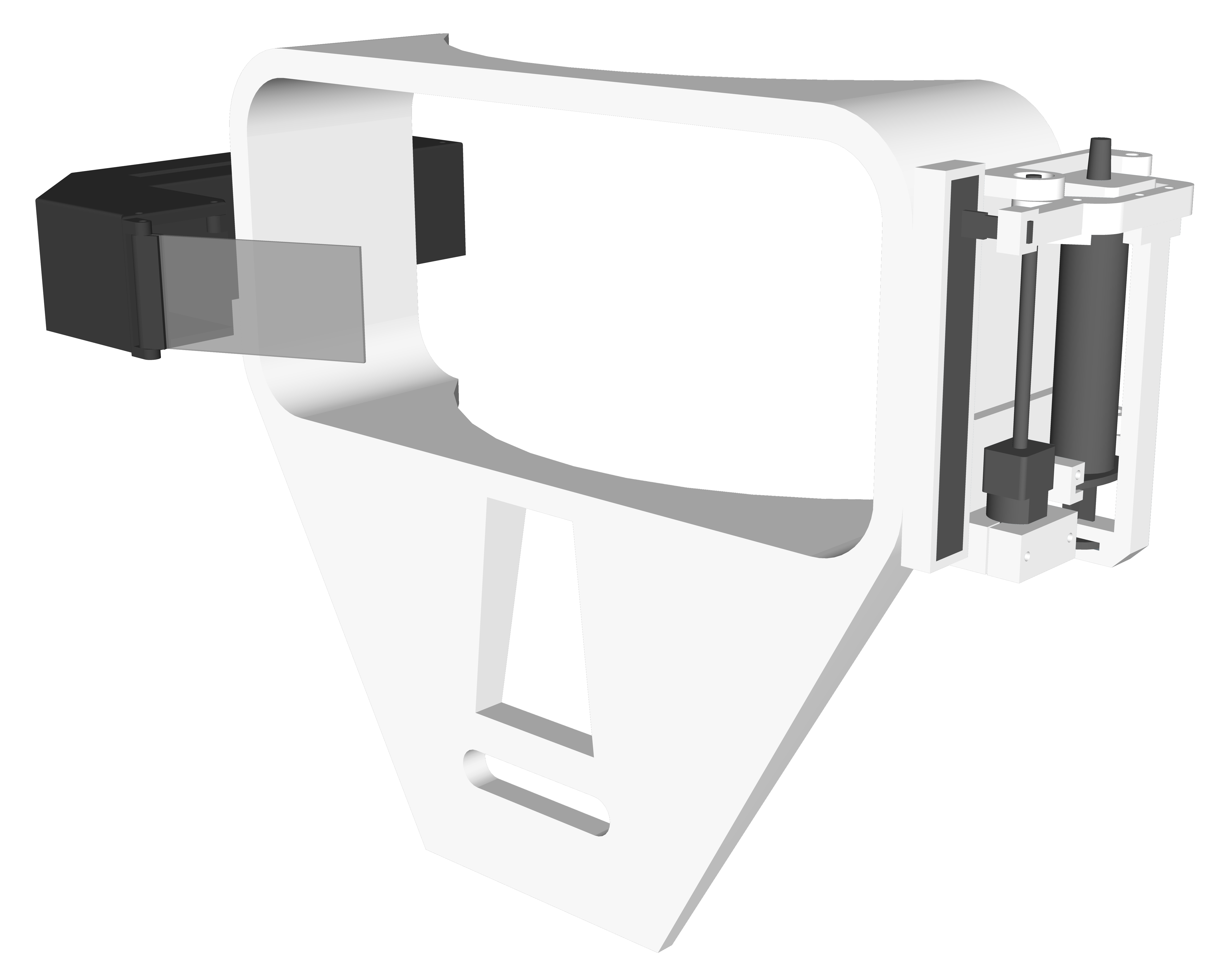
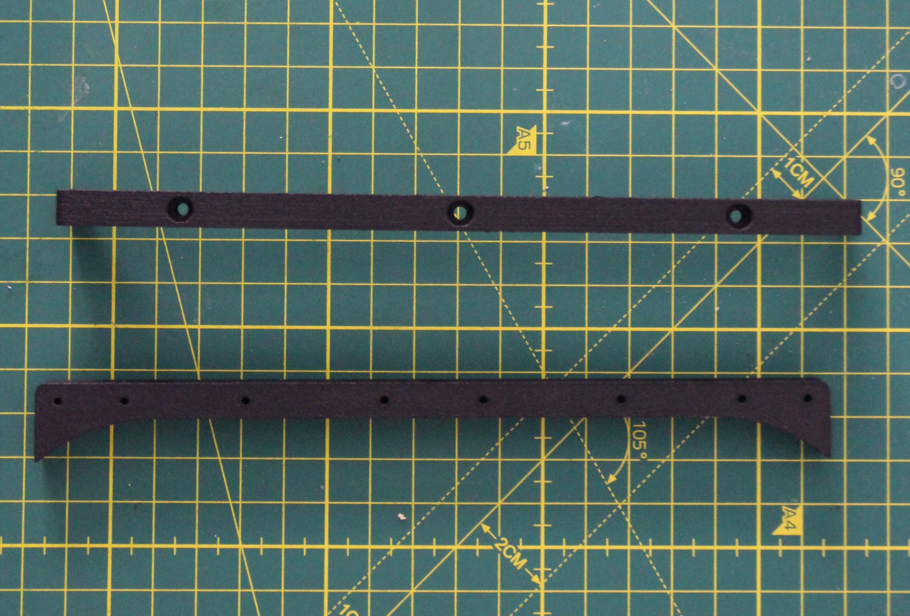
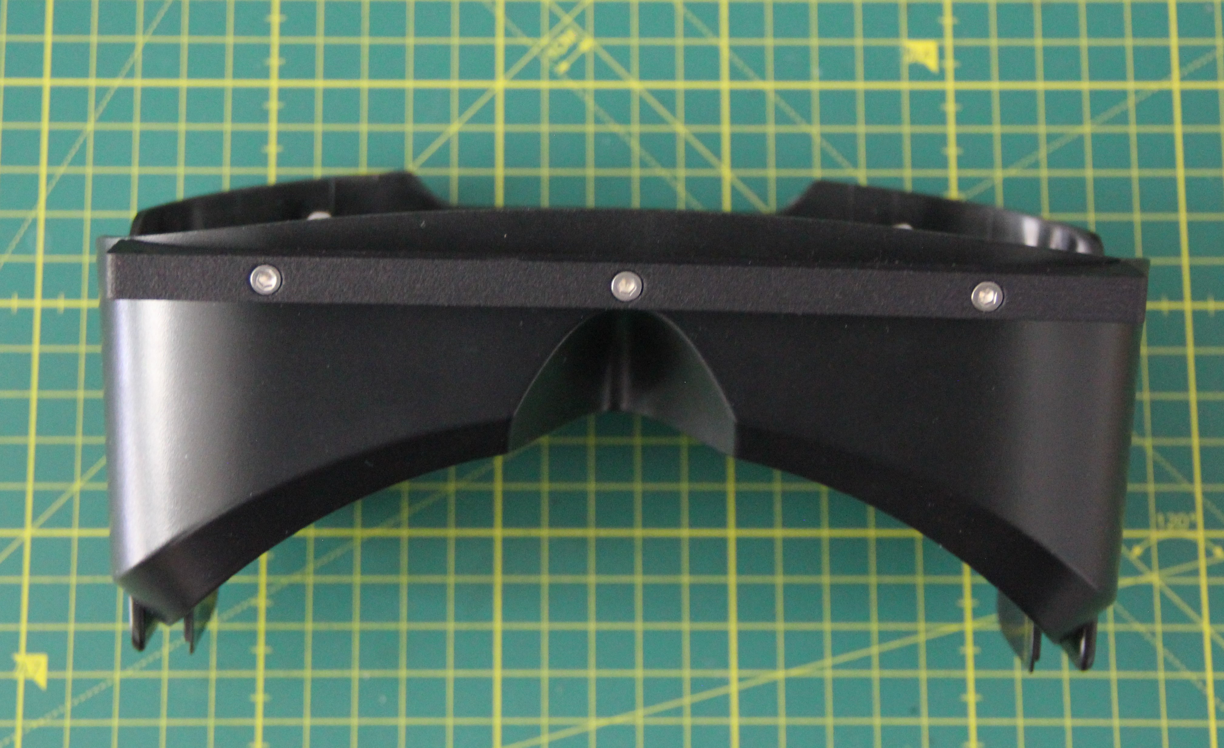
To attach something to the VR glasses skeleton, I designed two identical mounting brackets and had them printed using the SLS process. I'm not quite sure yet, but I think I'll make the rest of the mask entirely out of PCBs.

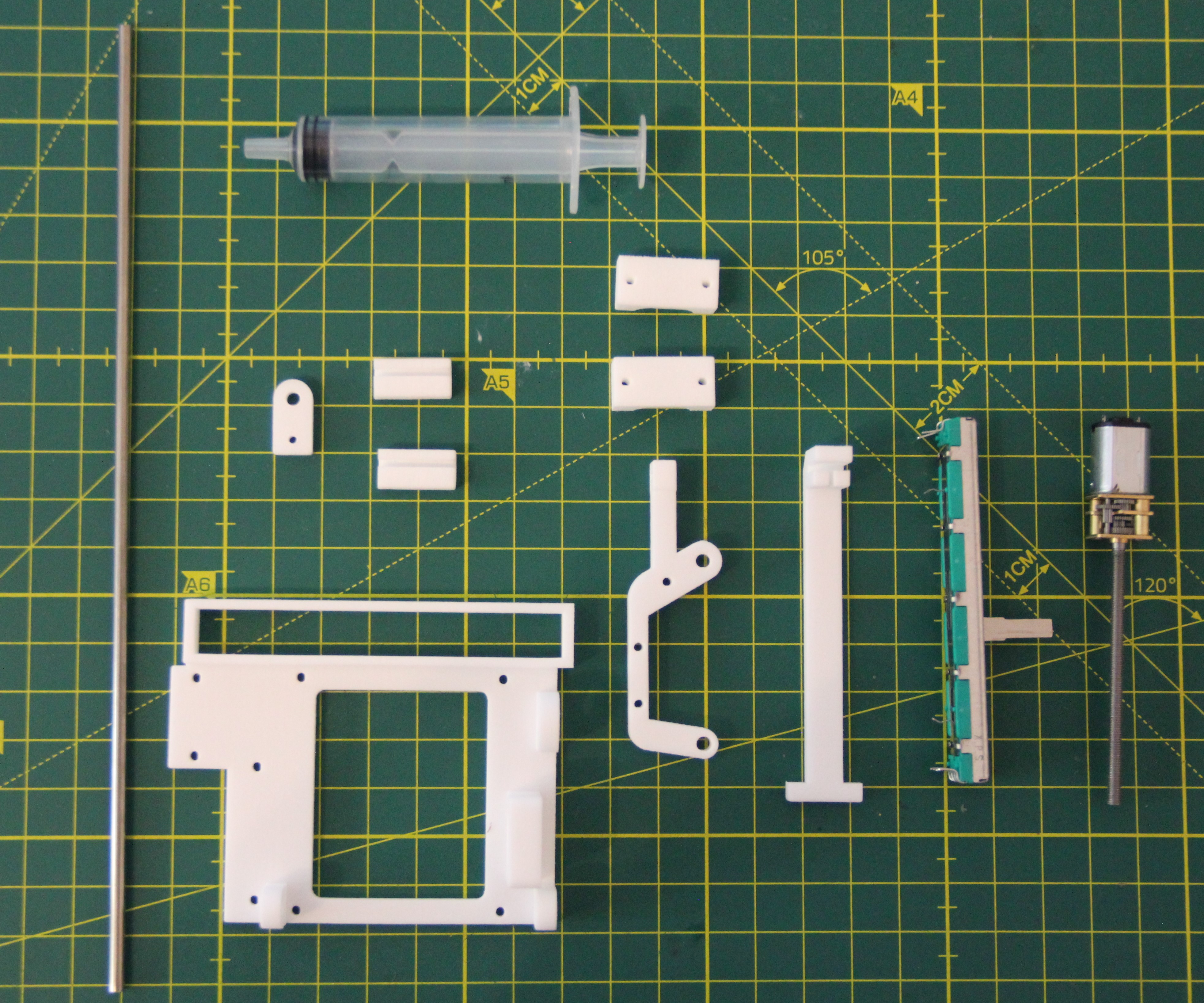
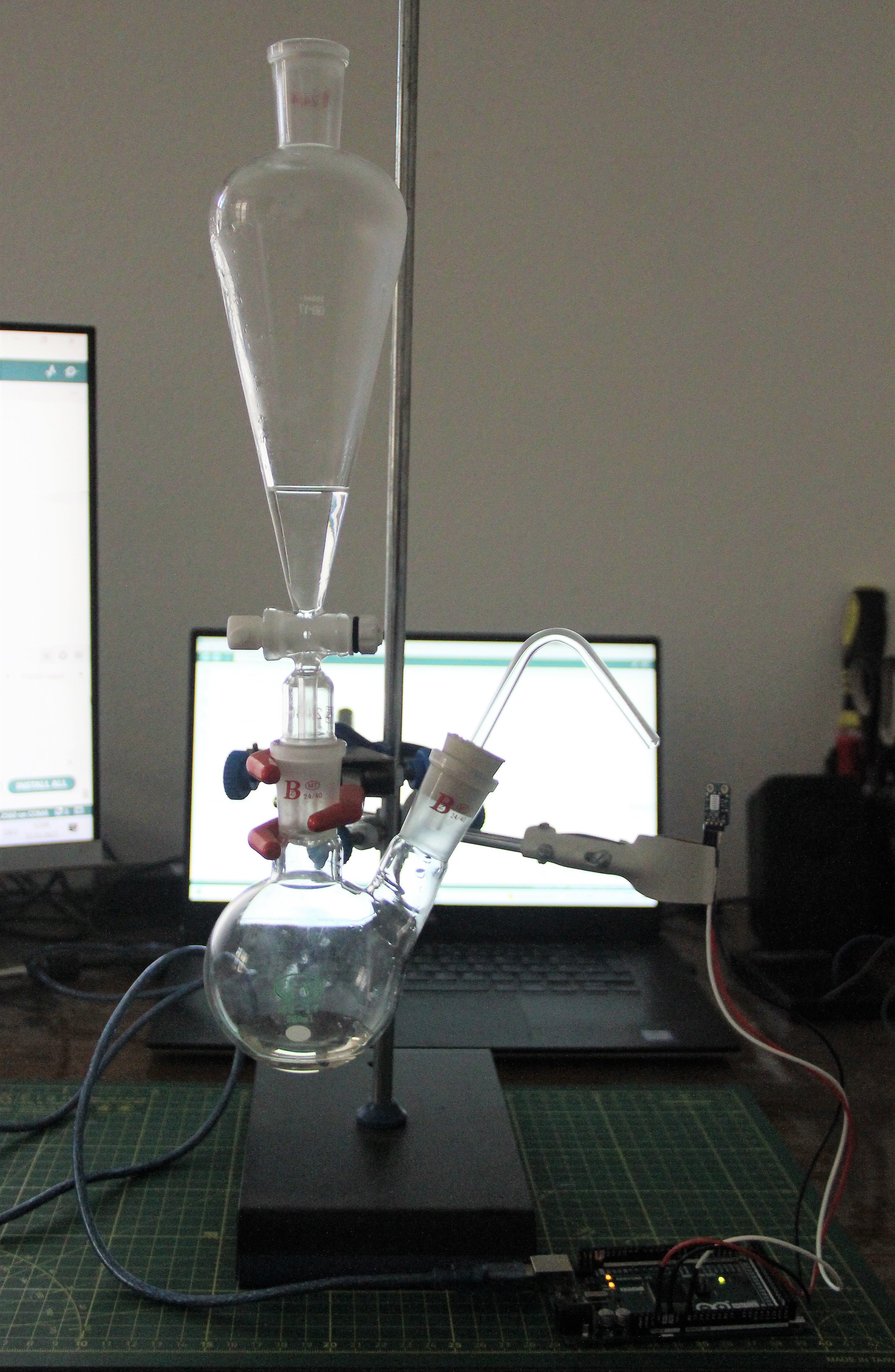
Syringe pump
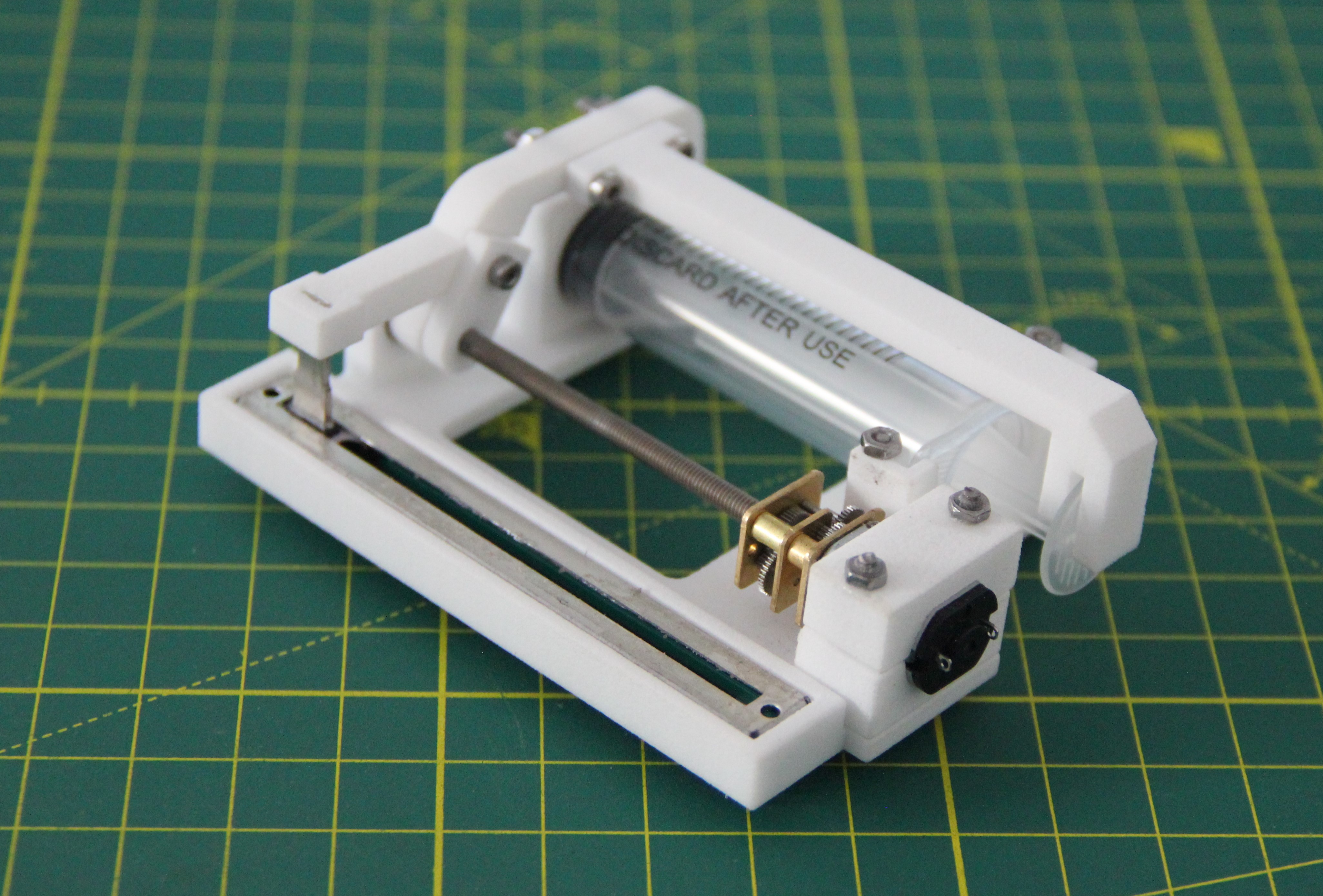
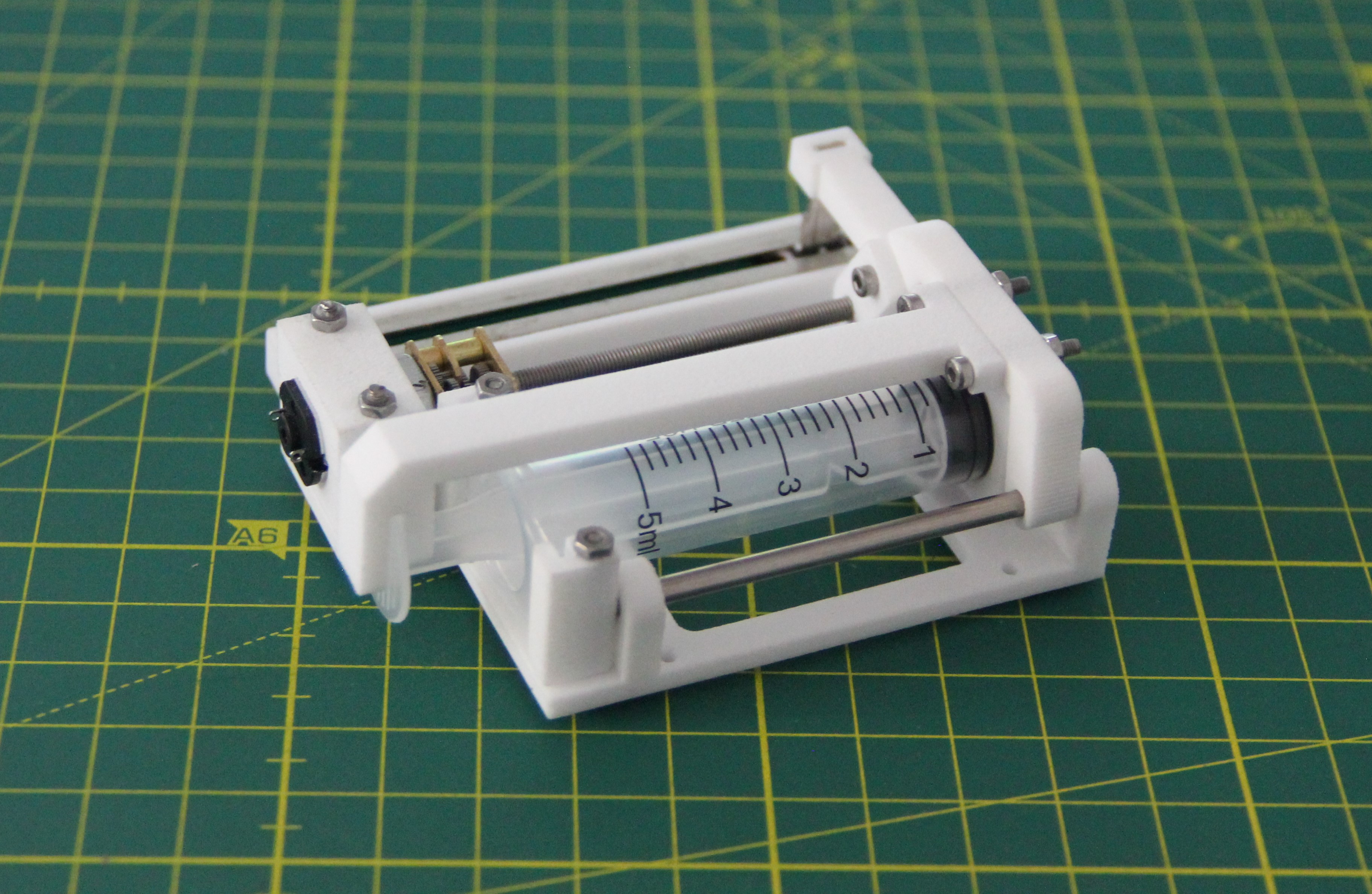
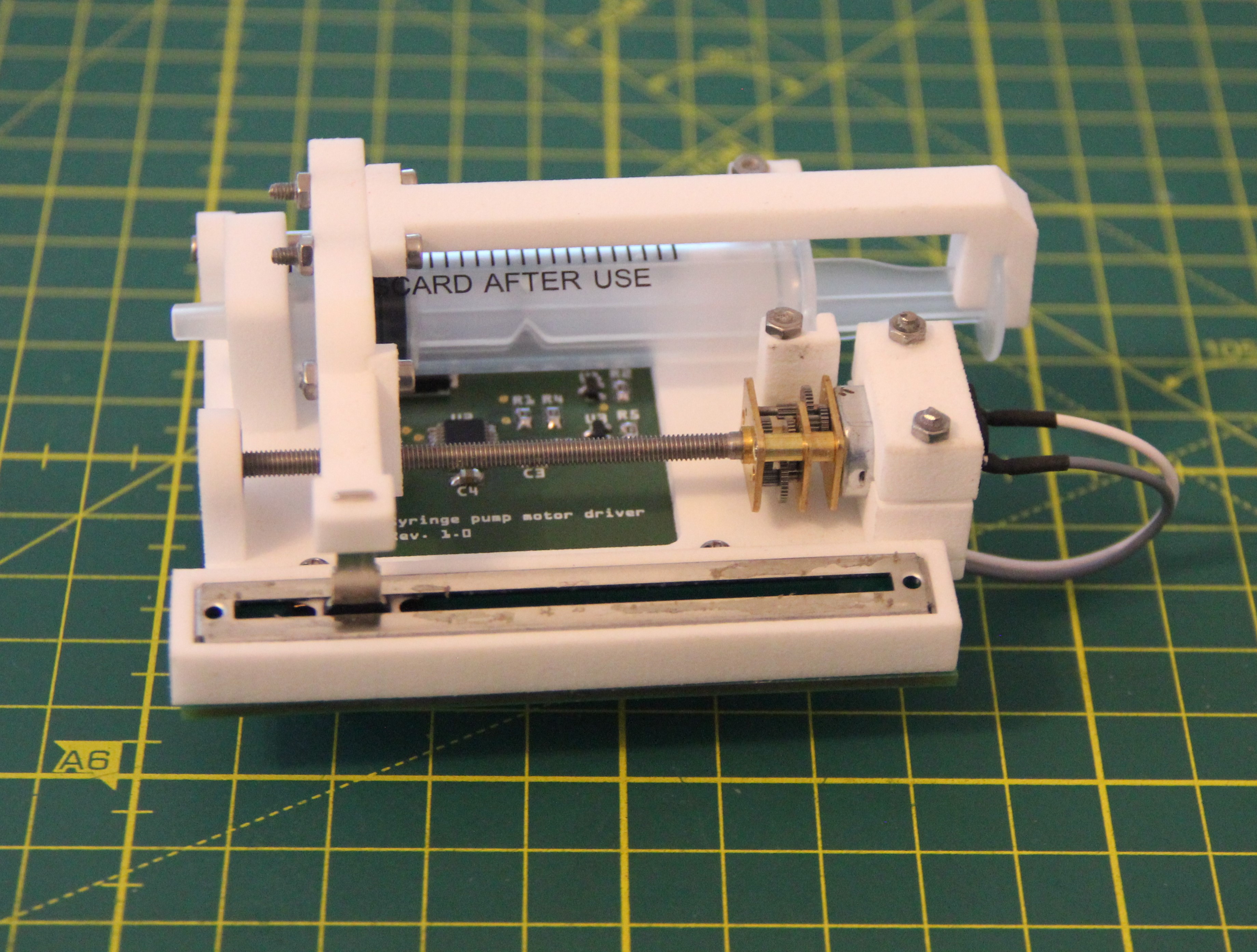
For the second prototype of the enhancer mask, I do not use a peristaltic pump, but a syringe pump. The peristaltic pump has three disadvantages: There is no feedback like a rotary encoder, you need an extra container for the medium and the pump is quite heavy due to the relatively large gear motor. All these disadvantages are eliminated by the syringe pump. For this reason, I have designed a mini syringe pump that uses a 5ml syringe. It consists of the following components. The white parts are laser sintered and made of PA12.
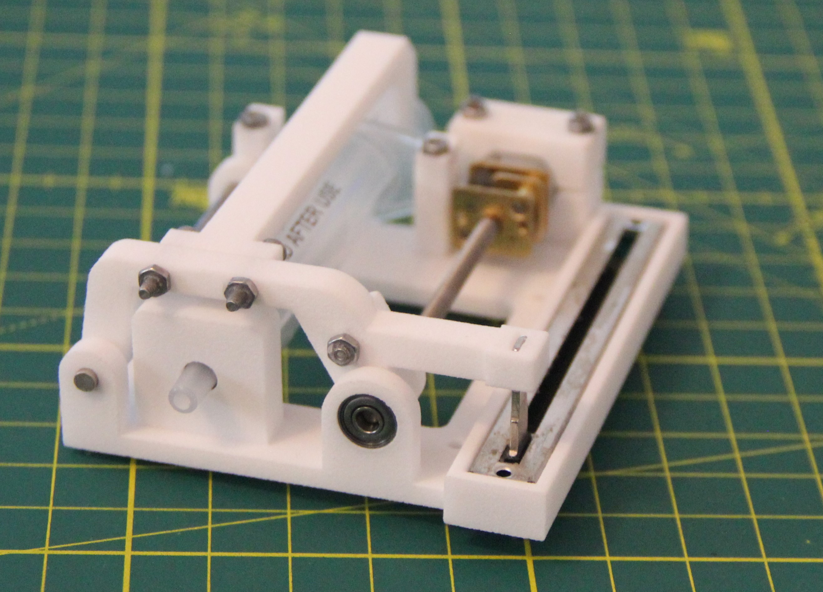
The syringe pump works flawlessly and I'm pretty happy with the design.
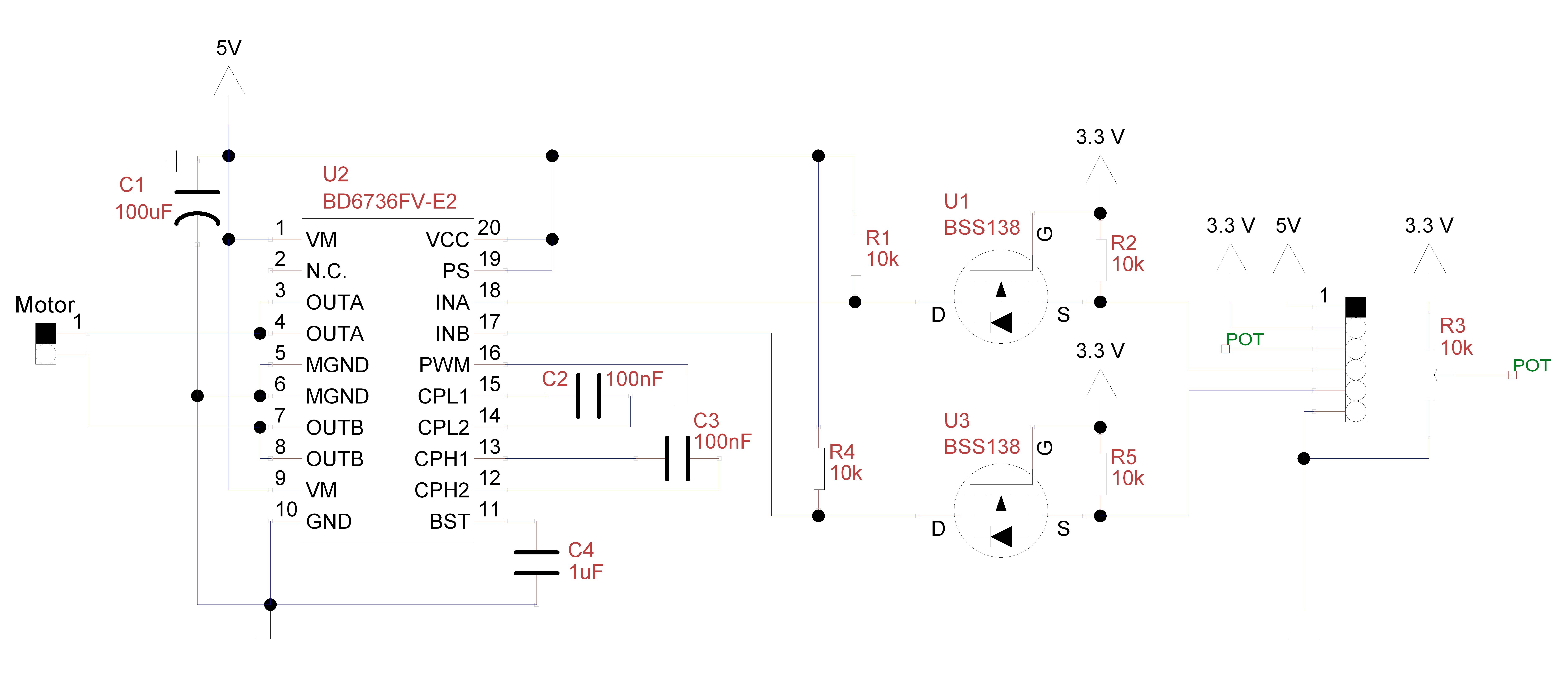
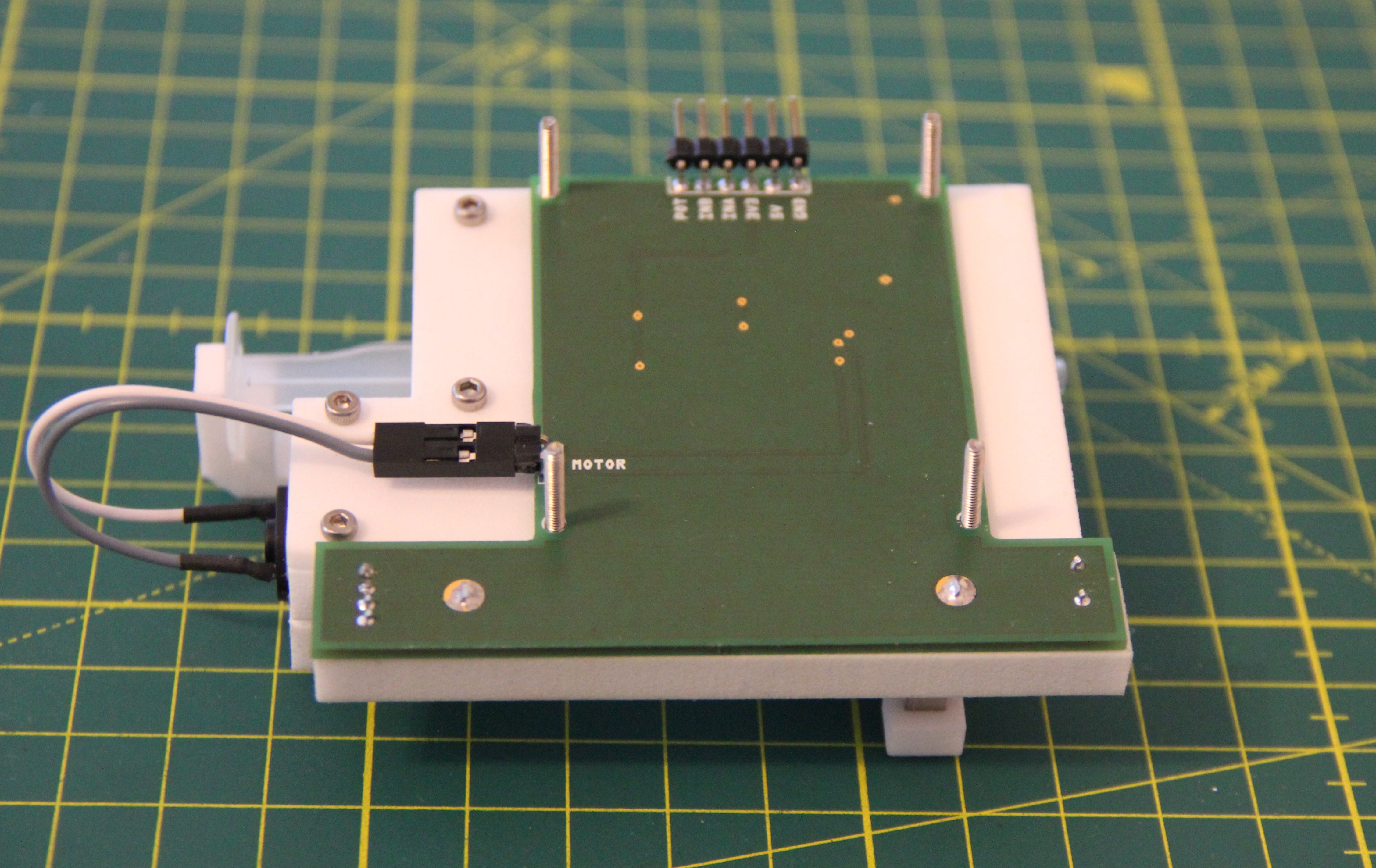
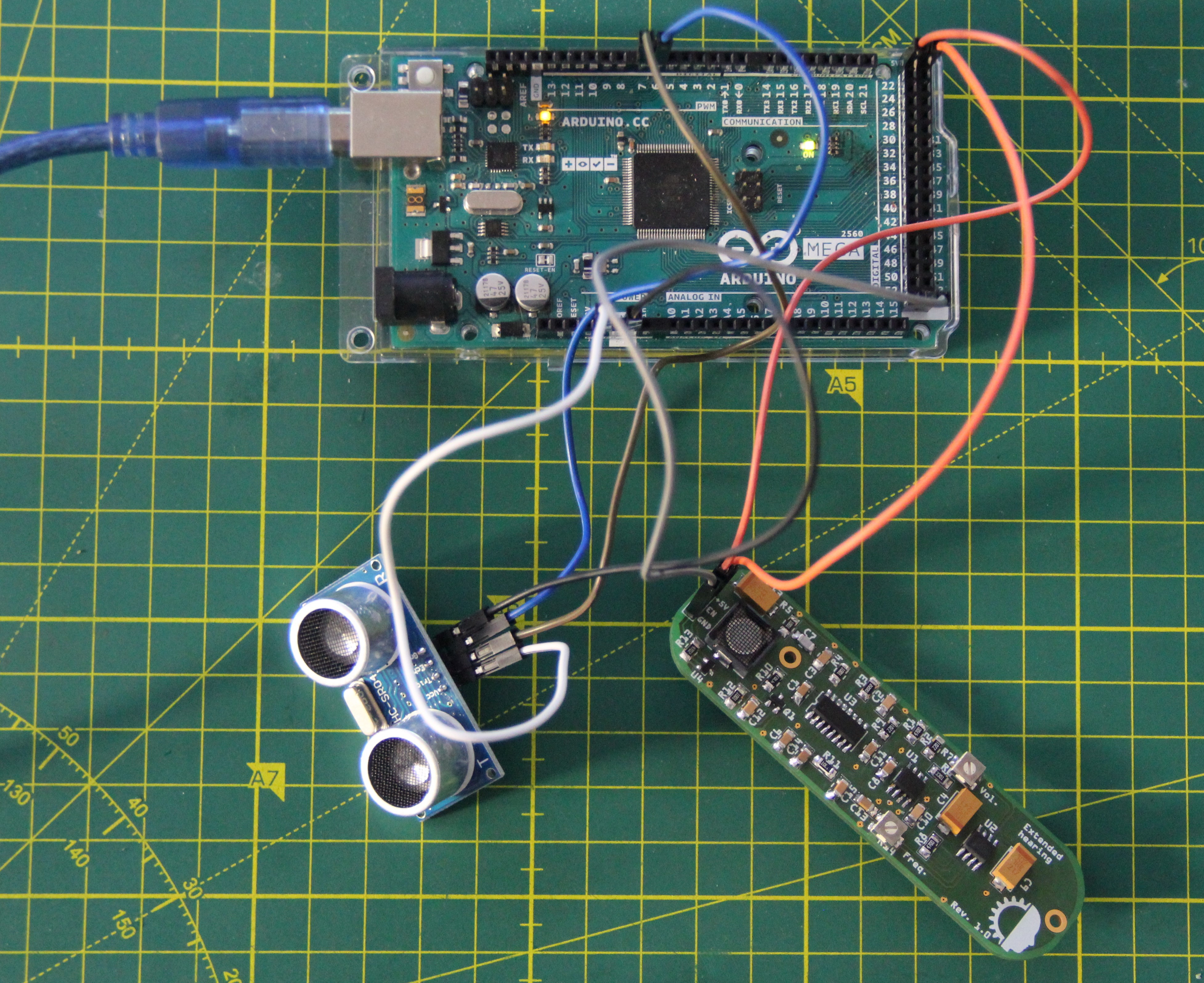
Of course, the pump needs a motor driver. Since the motor spindle already rotates quite slowly, PWM is obsolete. However, the motor must be able to rotate in both directions. My choice has fallen on the BD6736FV. The single H-bridge driver works with a motor power supply voltage of 2 to 9V, the same for the logic. Since I want to use a 3.3V microcontroller and 5V for the motor and the logic of the motor driver, level shifters are necessary. The bidirectional level shifters are a little overkill because INA and INB are just inputs. Two voltage dividers would have done as well, but this has the consequence that you can't change the power supply voltage so easily anymore.
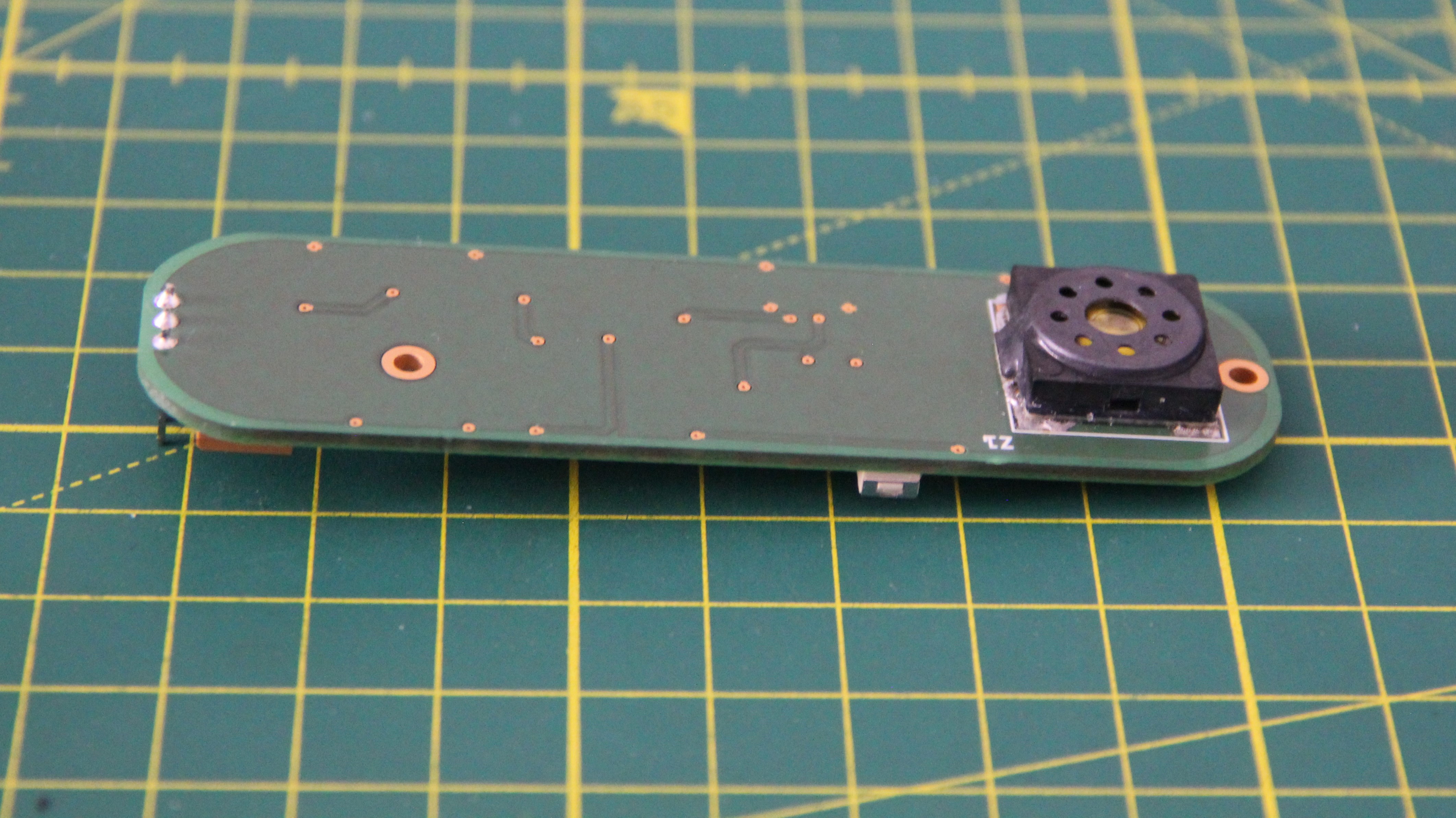
The PCB is mounted directly under the pump and therefore has a special shape.
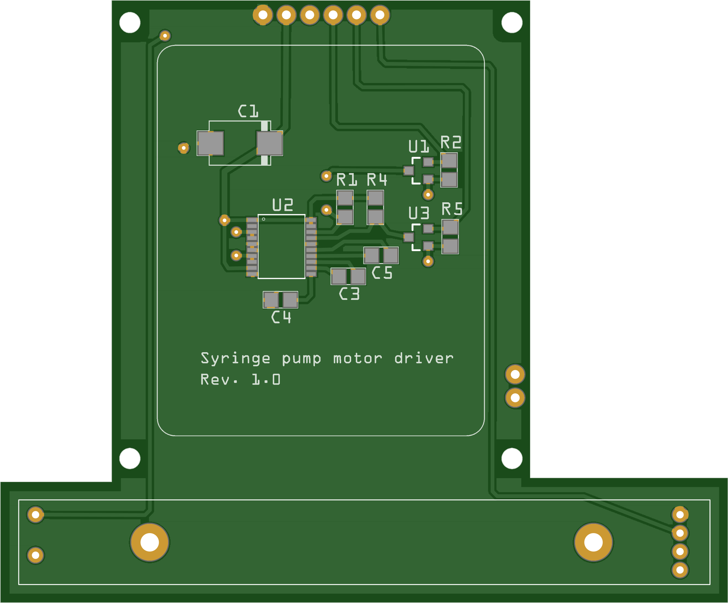
A stencil was used to populate the PCB since the BD6736FV has an SSOP-B20 package with a pin-to-pin distance of only 0.65mm. The slider pot will be soldered after testing.
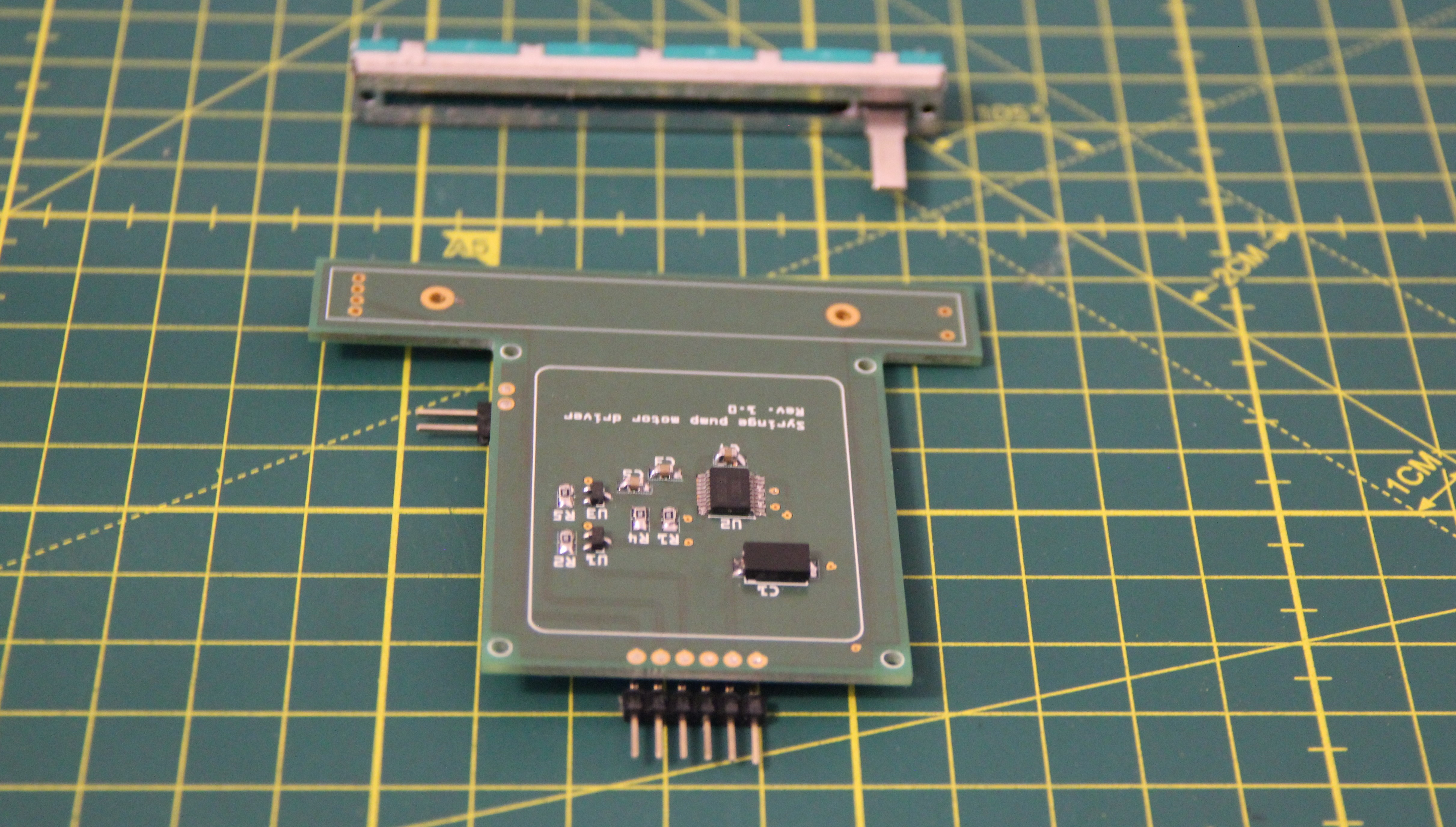
Since there was no magic blue smoke during the function test, I mounted the PCB below the syringe pump.
Optics
I still like the idea of using a transparent OLED as AR glasses. However, we need a lens if we don't want to mount the OLED 10 to 15 cm away from the eye. Since the salvaged lens of the VR glasses is predestined for this, I have designed an appropriate bracket that holds the lens, the OLED, and the associated circuit board. The bracket was printed using the SLS process and dyed black.
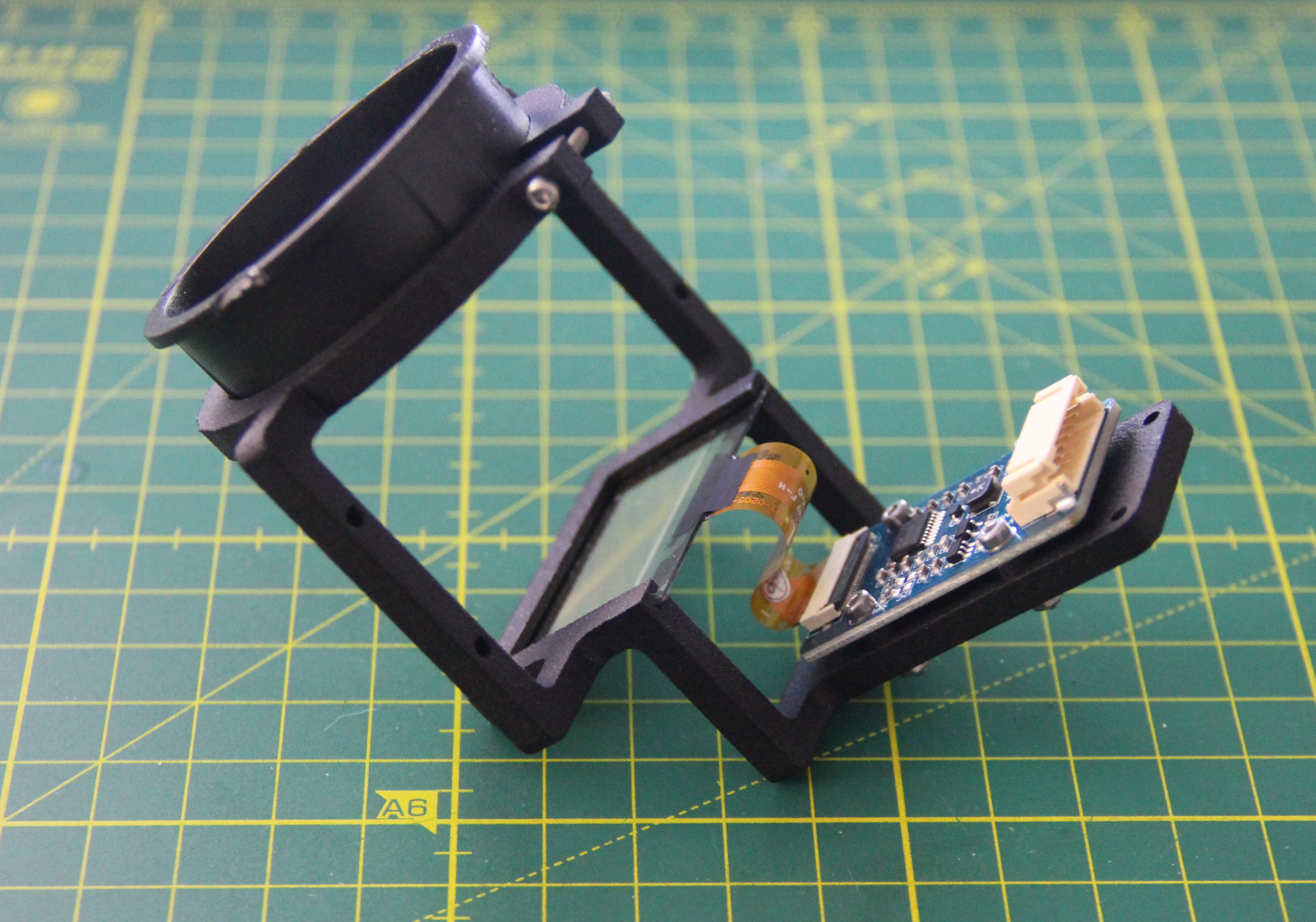
The plan is not to place the optics directly in front of the eye but to turn to the side so that you only look at the display when you turn your eye to the corresponding side....
Read more »

 jaromir.sukuba
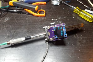
 owhite
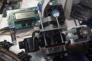
 James Newton