The enclosure was developed in Visio (I know, old school 2D CAD!) and output as SVG file.
First came the mockup:
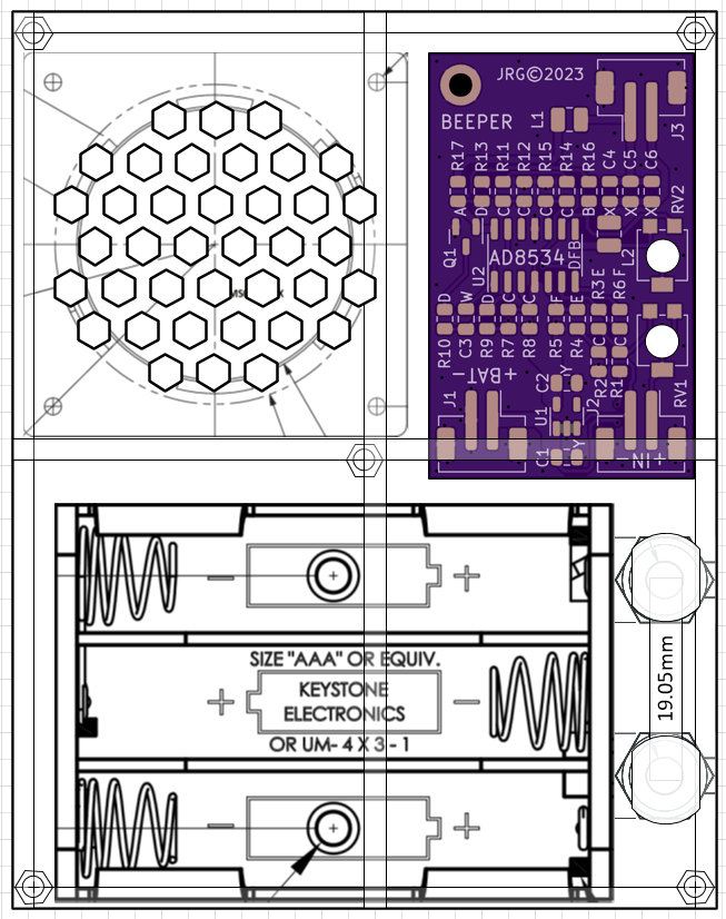
This mockup does not indicate any wall thickness, just the inside bottom area. I chose everything planar with a 15mm inside height, just enough to clear the bottom of the speaker, type CMS0361KLX by CUI. There's also a pair of standard banana jack (one will be black of course), a Keystone # 2480 3x AAA Battery Holder, and the previously mentioned Beeper PCB, 40x25mm.
After some consideration I decided to make the enclosure out of 6mm transparent acrylic, and used the method called "Pettis Joint" or "T Slot Joint" or “Interlocking T-Bolt Construction”, at least according to this page. This method leverages the accurate planar cutting of a laser to drill what amounts to a sideways hole. I bought some M3 square nuts and M3 x 12mm flat head screws, and designed a joint around their dimension.
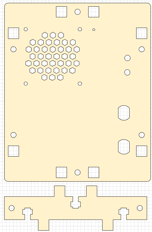
In this piece you can see the top with a speaker grill, and the front end piece. The two square holes along the bottom edge of the top mate with the two square pegs extending up from the front piece. The screw is inserted through the top, and the square nut slides into, detailed below.
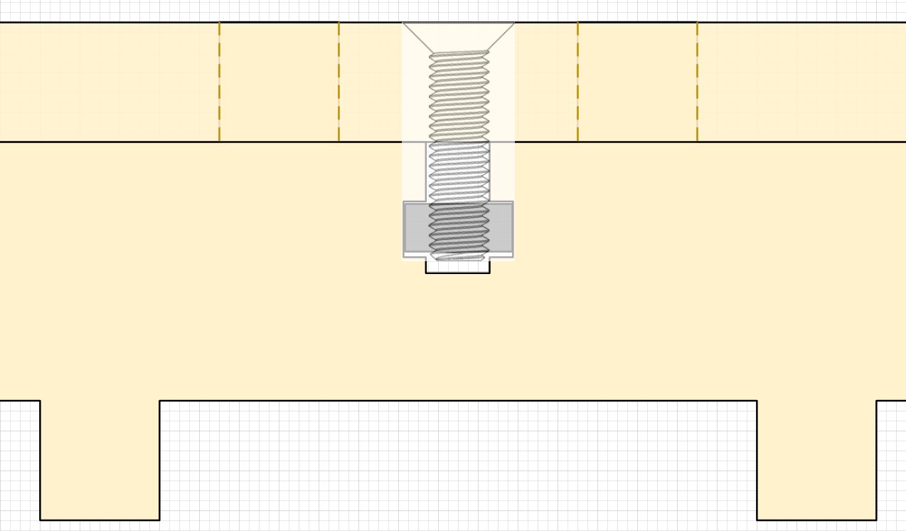
In this view one is looking at the front edge of the enclosure, and the top has been connected and fastened.
Once the design was all sorted out, I output the SVG file from Visio, and sent the files over to the people at Lone Pine Laser. Now we await the finished enclosure!
Discussions
Become a Hackaday.io Member
Create an account to leave a comment. Already have an account? Log In.