 Remi Serriere
Not all GPS receivers are alike!
The GPS receiver I first ordered on Amazon is not designed to be used as an accurate time source. Don't get me wrong, the U-Blox NEO-6M is a good receiver but it was designed as a general-purpose GPS receiver. It processes and outputs the location every second, that's a waste of resources and a potential source of time drift. On top of that, the device would not accept a lot of commands from the U-Blox Center software which lead me to suspect I have a cheap Chinese clone... Oh well...
Many dedicated GPS time sources can be found on eBay, mostly reclaimed from "starter kits" or cellular towers. If you know what you are looking for, gems can be found for cheap. Some units are even equipped with TCXO, OCXO, or DCXO if you are lucky. More on that later maybe :)
There is one important thing to keep in mind with this kind of device: they require a stationary antenna! They are designed to stay in the same place, not to be moved around. A time-dedicated GPS receiver should stop reporting its position after a specific, sometimes configurable, amount of time. During this first phase of operation, the chip would average its position and then save it in its memory. After that, the chip would only report the time of day, some internal status for monitoring purposes, and PPS.
Trimble 66266
The first time-oriented GPS receiver I ordered was a Trimble board based on a Trimble 66266, for less than $15 on eBay probably reclaimed from a Trimble starter kit.

It has an SMB antenna connector and a 3.3v to 5v active antenna is needed. These receivers are quite accurate, down to 15 ns according to the datasheet.
Fortunately, the kit's user guide is still available and has all the information we need including the board's pinout (the connector is a 2.00 mm pitch 2x4 pins, not a standard 2.54 mm):
| Pin number | Function | Description |
|---|---|---|
| 1 | Antenna power input | 3.0 V DC to 5.5 V DC, 55 mA max |
| 2 | Prime power input | 3.3 V DC ±0.3 V DC |
| 3 | TXD A | Port A transmit, CMOS |
| 4 | Reserved | Reserved |
| 5 | RXD A | Port A receive, CMOS |
| 6 | 1 PPS | One Pulse-Per-Second, CMOS |
| 7 | No connect | Not used |
| 8 | GND | Ground, Power and Signal |
The user guide can be downloaded from here or from this project's main page.
By default, the chip should have the following configuration:
| Setting | Value | Description |
|---|---|---|
| Serial port | 9600/8/Odd/1/None | Baud rate/Data bits/Parity/Stop bits/Flow control |
| Protocol | TSIP | Proprietary binary "Trimble Standard Interface Protocol" by default NMEA disabled, can be activated but not needed |
| PPS | Always on, rising edge | Always on, with or without a GPS signal Can be set to "only when 1 or 3 satellites are in use" |
| Self-Survey | Enabled, autosave, 2000 | Self-survey enabled by default The position is saved to flash on self-survey completion 2000 fixes are required until self-survey completion |
After ordering an SMB to SMA cable adapter and a second active GPS antenna, it was time to hook this new toy to a computer. The Meru NTP server is in semi-production right now, so it will not be used... For now! I will not talk about the wiring much here because everything is temporary and not related to the Meru server.
Lady Heather to the rescue for the first power-up
Lady Heather is a great piece of art! But a rather complicated software. Since the GPS receiver is also complicated to talk to, with a proprietary protocol, I figured this software could be of good use. Indeed it was! However:
- While you can build and run it on Linux, the installer is made for Windows.
- It needs a serial port with DCD support, even if you don't care about PPS for now.
- Most USB to Serial interfaces don't support DCD, I used the same RS232-TTL board as before on my Windows workstation for that reason, connected to the DB9 RS232 port on the motherboard.
Version 5.0 can be downloaded from here and can be upgraded to version 6.14 Beta.
If the GPS is connected to COM1, simply execute the shortcut on the desktop. Lady Heather will try to autodetect and autoconfigure the GPS. If you are using another COM port, let's say COM3, then execute the program with the argument "/3" where 3 would be the COM number (COM3).
With the software running, you should see the device progressing through the self-survey mode while acquiring your position. If it is already locked to a position, the chip must be reset... Read along to the next chapter.
In the following screenshot, we can see:
- Lady Heather is connected to the Trimble 66266 board on COM1.
- Self-survey is still going:
- Sampling is set to 2000.
- Progress: 38%.
- 2D/3D position (lat/lon/alt) is slightly changing over time.
- The position has not been saved yet (red alert near the cyan analog clock with satellite positions).
- Actually, the chip is reporting a lot of information:
- Its name is "RESOLUTION SMT".
- Manufacturing date.
- Temperature.
- ROM/RAM/OSC/FPGA and Power status.
- Antenna status (open, short-circuit, ok...).
- Almanac status.
- PPS status...

After letting the GPS run for a while, Lady Heather is now indicating the following information:
- Self-survey is complete:
- Survey data are grayed, and progress is at 100%.
- The position is in white, in a locked state.
- The red alert turned green indicating the position has been saved to flash.

Is it GPSD friendly?
Yes, GPSD does support its proprietary protocol so let's connect the board to a Linux computer. However, the monitoring tool "gpsmon" doesn't support Trimble devices much, and "cgps" must be used instead. The following pictures show 2 very specific "cgps" this device will output (the glary zone is the listing of the tracked satellites):


What language does this thing speak?
TSIP of course! Which is a proprietary binary protocol...
Ok, that's great, but I moved the antenna (or the device came pre-locked from China), how do I reset the chip to factory default? Easy: download the Trimble starter kit user guide, go to Appendix A, and read through 44 pages of instructions... or simply read the following summary ;)
Let's say the board is connected to /dev/ttyUSB0, we can simply use the "echo" command to send raw hexadecimal data to the chip:
# Hexadecimal packet structure:
# Byte 1 = "DLE" byte, always 0x10
# Byte 2 = Command ID
# Byte 3-n = Payload
# Ending bytes = DLE then ETX, always 0x10 0x03

# Factory reset
# Command ID = 0x1E
# Payload:
#    0x4B = Cold reset
#    0x46 = Factory reset
echo -en '\x10\x1E\x46\x10\x03' > /dev/ttyUSB0

# The chip will reboot, wait at least 2 seconds before sending other commands or they will be ignored

# PPS output configuration
# Command ID = 0x8E 0x4E (2 bytes long)
# Payload :
#    0x02 = PPS is always on. PPS is generated every second.
#    0x03 = PPS is output when at least one satellite is tracking. PPS is generated every second.
#    0x04 = PPS is output when at least three satellites are tracking. PPS is generated every second.
#    0x82 = PPS is always on. PPS is generated every even second.
#    0x83 = PPS is output when at least one satellite is tracking. PPS is generated every even second.
#    0x84 = PPS is output when at least three satellites are tracking. PPS is generated every even second.
echo -en '\x10\x8E\x4E\x04\x10\x03' > /dev/ttyUSB0

# Save device configuration to flash
# Command ID = 0x8E 0x26 (2 bytes long)
# No payload
echo -en '\x10\x8E\x26\x10\x03' > /dev/ttyUSB0
It is also possible to only restart the self-survey. This is useful if you find out the stored location doesn't accurately match where you are located, or if the 2000 samples were not enough to acquire a stable location but you don't want to change this setting.
# Self-survey
# Command ID = 0x8E 0xA6 (2 bytes long)
# Payload:
#    0x00 = Restart self-survey
#    0x01 = Save position to flash
#    0x02 = Delete position from flash
echo -en '\x10\x8E\xA6\x00\x10\x03' > /dev/ttyUSB0
And sure enough, CGPS is now reporting a slightly changing position for the next 2000 samples:

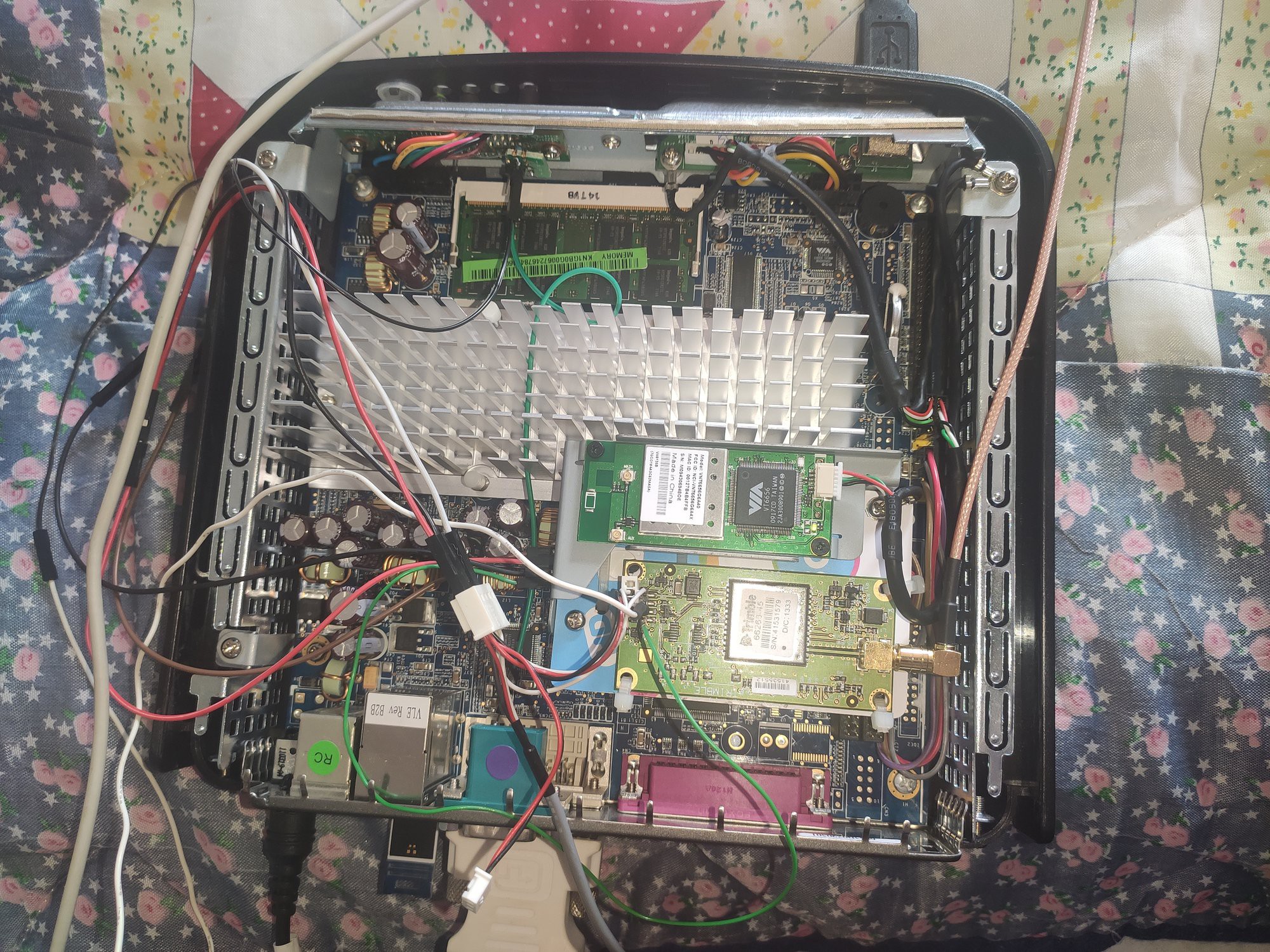
Just a little treat: this picture shows the Trimble board installed in a WYSE V90LE, slightly modded, running Debian 11.7. I might convert this "computer" to a time server at some point. Don't pay too much attention to the wiring, this is a temporary setup ;)
What's next?
Another time-dedicated GPS receiver is on its way, as well as some 2.00 mm pitch IDC cables. I also want to compare the NEO-6M PPS output against this Trimble unit, to see if one is more reliable than the other...
This Trimble board has a lot of unpopulated components, it looks like there is room for an LVDS chip of some kind and two U.FL connectors. One U.FL is directly connected to the 1PPS TTL output, the second goes to where the LVDS would be (a 10 MHz output maybe?). It could be nice to solder a U.FL connector to the 1PPS line to add a BNC output to the Meru...
Stay tuned!
Discussions
Become a Hackaday.io Member
Create an account to leave a comment. Already have an account? Log In.