 MS-BOSS
Description
This is an analog guitar effect which works as octave-down effect. Contrary to all available analog octave-down effect (let me know if you find one!), it produces undistorted sinewave (when supplied with pure sinewave on input). There is no PLL, no oscillator
Overview
So, you may want to know how it works. A long time ago, I was experimenting with octave-up effects. Recently, I thought that the principle of octave-up effects can be turned inside-out and a bit expanded to make an octave-down effect. The way most octave-up effects work (the good ones, simple ones only rectify the input waveform which is horrible) is as follows:
=\frac{sin(2x)}{2}+\frac{1}{2}")
If this function is inverted, you get:
}{2}+\frac{1}{2}}=|sin(\frac{x}{2})|")
However, this is not enough to turn sinewave into sinewave of half frequency. You need to remove the absolute value and this is where the analog mojo kicks in. If you want more insight, look in the presentation where simulated waveforms can be found. If you are more curious, look into the schematics or simulation.
Explanation of function
To sum it up, the circuit does the following: detect input amplitude and shift the input signal in such a way that the sinewave has its minimum at precisely 0 Vdc, find a square root of the shifted signal and normalize its amplitude so that input and output amplitudes are equal, then invert the signal at points where it gets closest to zero.
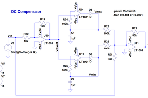
90deg phasing circuit
In order to detect extremes, you need to detect zero crossing of a derivation of the input signal. Initially, derivator was used, but it had several issues, most importantly its sensitivity was increasing with frequency whereas I needed quite the opposite, because the circuit needs to be most sensitive in the range of tens of Hz to several hundreds of Hz. The sensitivity also should decrease with rising frequency to make the phasing circuit more immune to harmonics (because signal from guitar is going to be flooded with harmonics). So a double integrator was used - one for the phasing circuit, one as DC servo. However, this circuit has a nasty peak at 32 Hz, so it had to be compensated with a Twin-T notch filter right on the input of the whole effect. It maintains proper 90deg +- 0.25deg phase from about 60 Hz and up. There is an additional RC T-network to accelerate convergence to 90deg at low frequencies, which allows for more gain in the integrator by using shorter time constant. It should work even with harmonic-rich signals, however the harmonics must be in phase (and not antiphase) with the fundamental frequency, otherwise an analysis of what will happen is nontrivial.
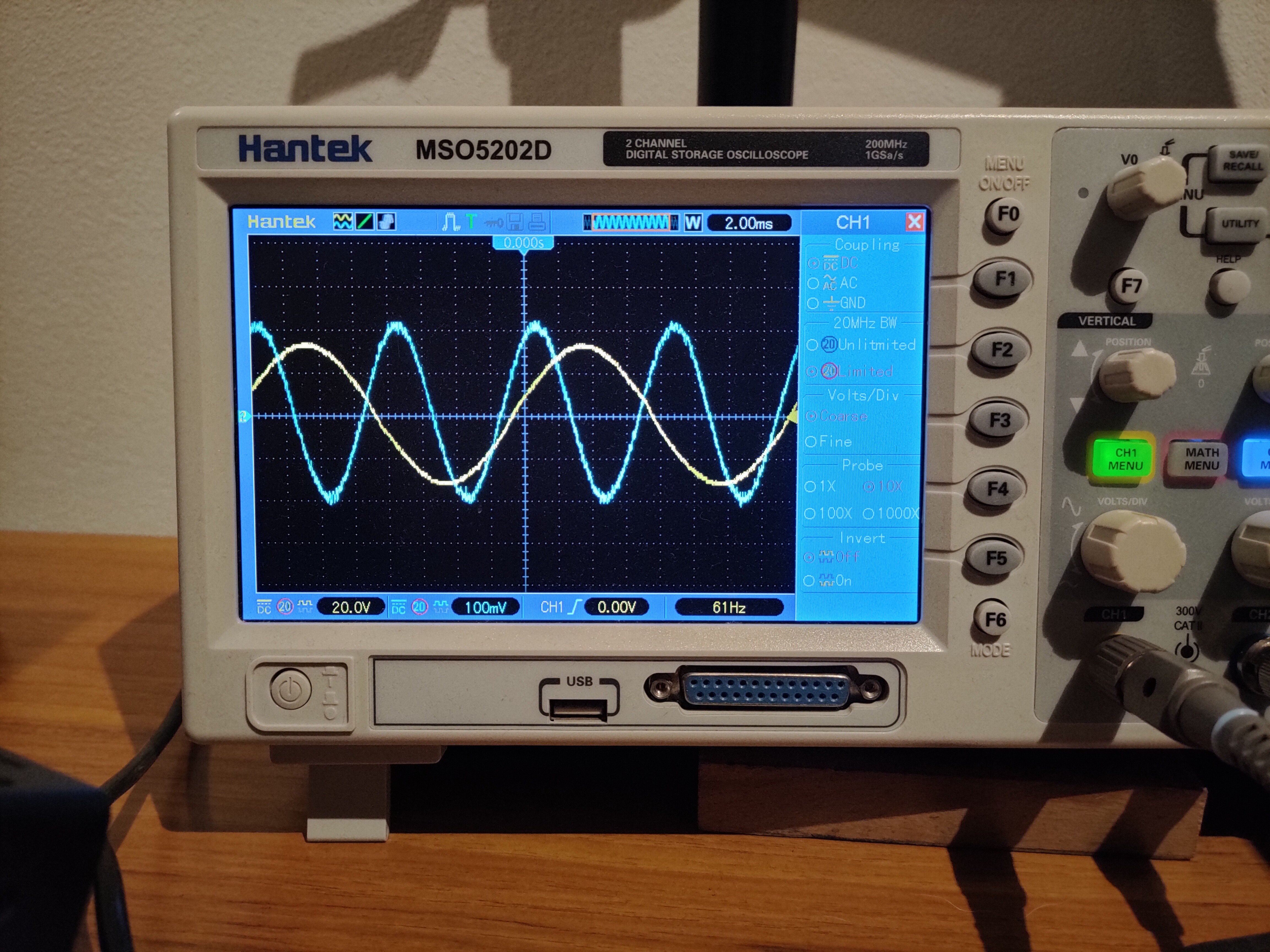
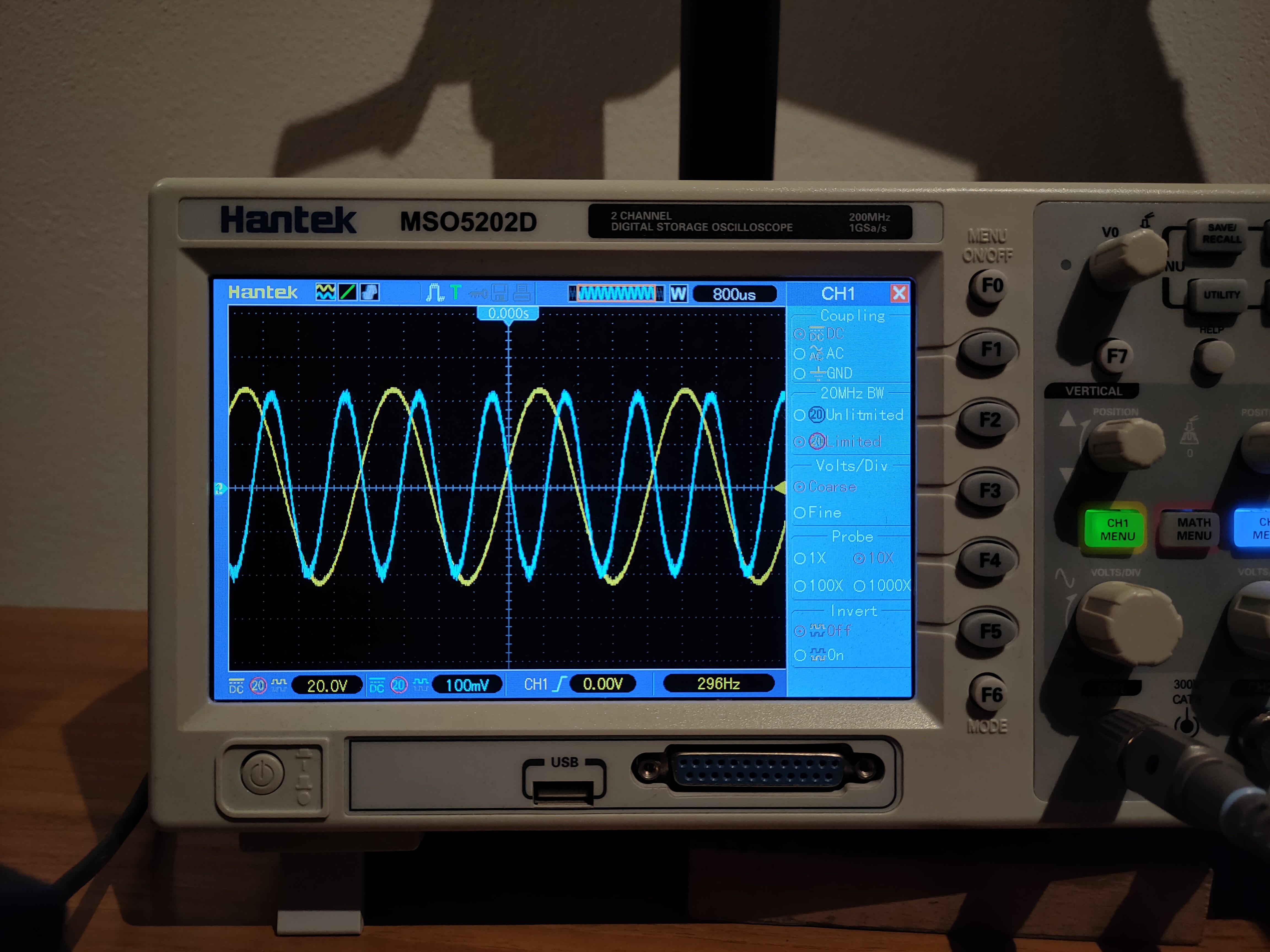
Schematics of the input circuit with the notch filter and the phasing circuit:

Green sine is the input waveform, blue is the 90deg shifted sine, red is output of the comparator:

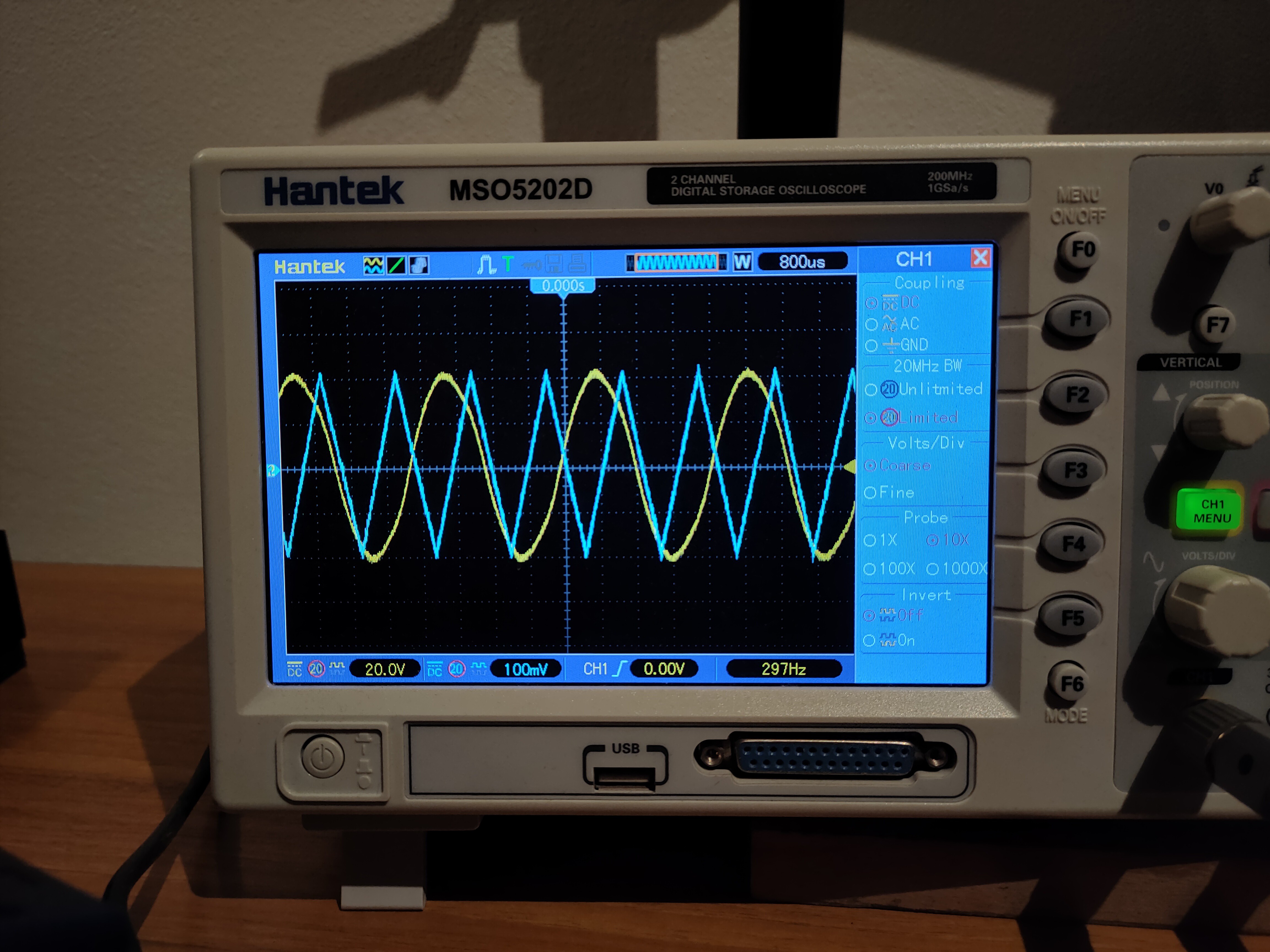
Synchronous peak detector
There is a synchronous peak detector which uses 2 track-and-hold amplifiers (historical LF398). One of them tracks the input signal while the second one holds a peak value. Each time the input waveform goes through one of its extremes, their tasks are switched. At the same time, an analog switch selects the one which holds the peak value. This way, you get a fairly precise DC value representing the amplitude which is updated after each cycle of the sinewave. This was needed because regular peak detectors were too slow to react fast enough to dynamics of playing a guitar while being too fast to hold their value during the whole cycle of sinewave, so they would cause a lot of distortion and bad dynamics. This part and the phasing circuit proved to be crucial for proper operation of the whole effect.
Green sine is the input waveform, blue and light blue waveforms are outputs of the track-and-hold amplifiers:

Square root finder
The square root finder is quite simple - it uses opamps and diodes to calculate the logarithm of the DC shifted signal, then divide by two (simple resistor divider) and exponentiate. This computes the square root even with proper...
Read more »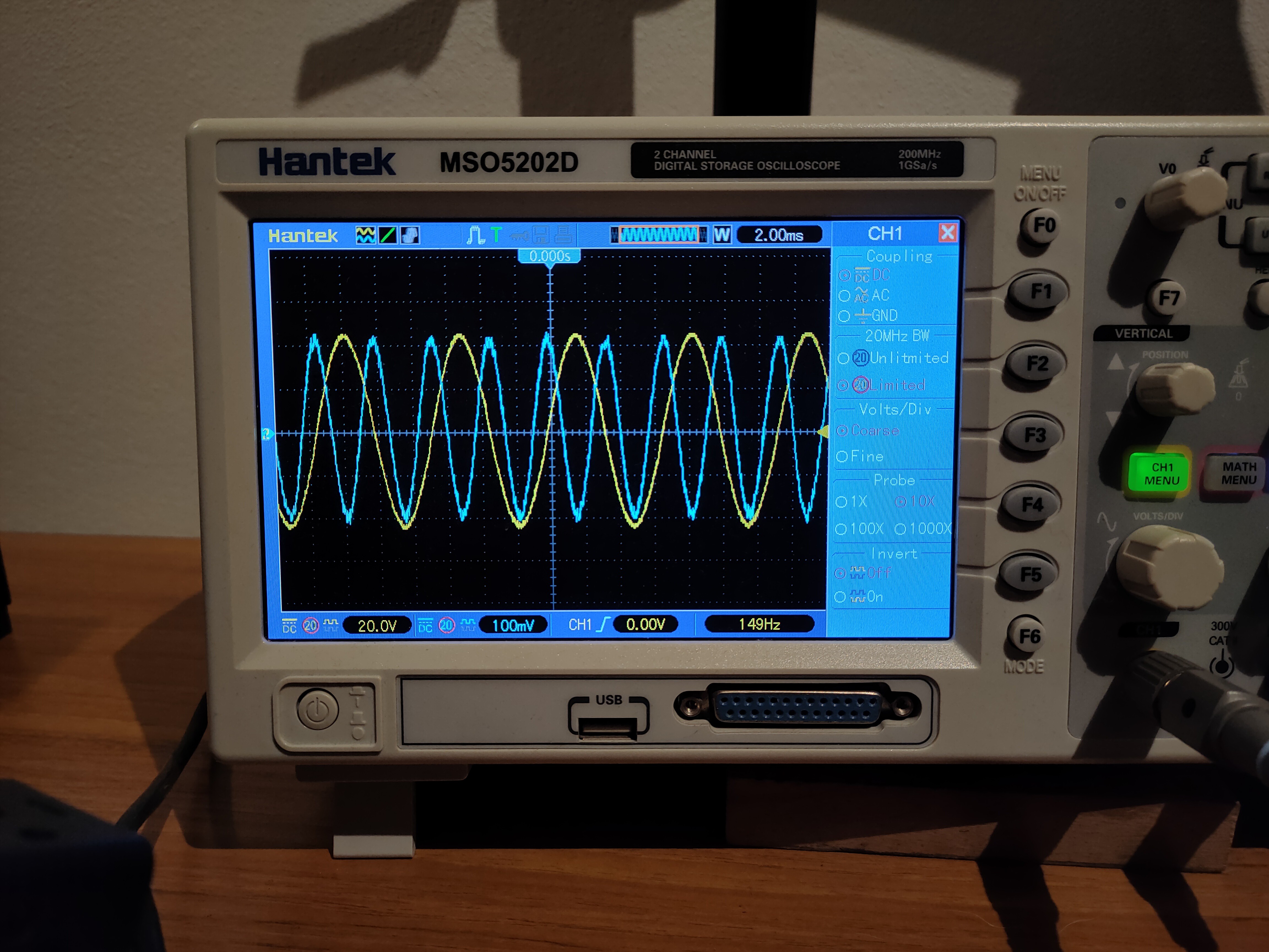


 Adam Gulyas
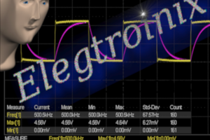
 Ringo2k
 Bruce Land
 agp.cooper
Hello, I sent you a PM