After a few nights plunking away on LTSpice, I finally had a working regulator.
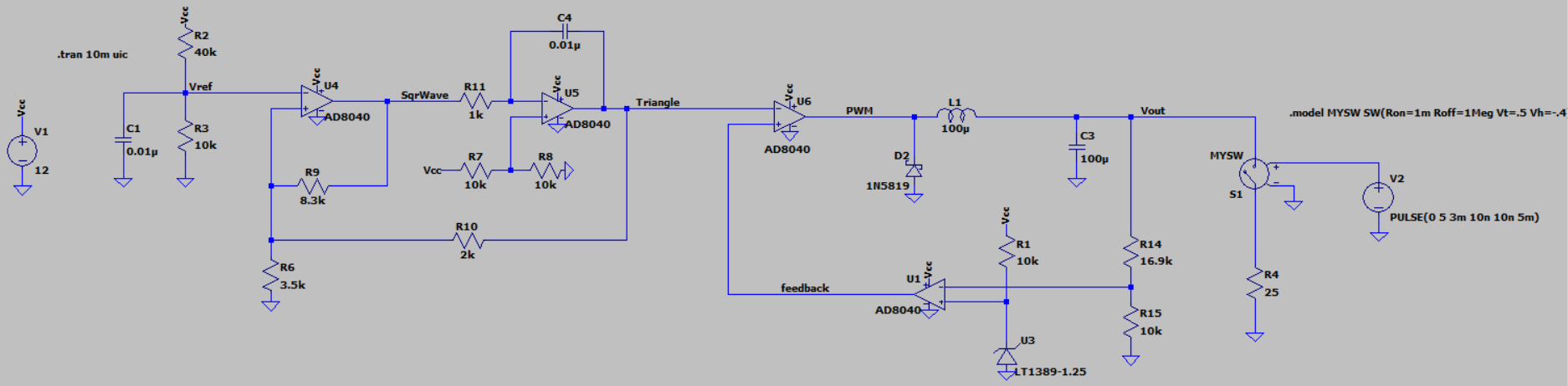
U4 is a Schmitt Trigger used to make a square wave. R2, R3 shift the switching thresholds for it up into positive voltages. R9, R6 set the thresholds and R10 moves them depending on if the next stage (U5) is ramping up or ramping down.
U5 is the integrator, which converts the square wave input from U4 into a triangle wave output. The output of which is fed back to the Schmitt Trigger to cause it to toggle. Together they form a stable oscillator with a triangle wave output.
Next is U6. It compares the present value of the triangle wave to a threshold (feedback) value and as that value changes, the output will toggle based on the portion of the triangle wave being fed into the negative input. This creates the PWM.
The PWM is then fed into the LC filter of the buck circuit, then R14,R15 sample the output voltage and feed it back into U1. U1 acts as a comparator and compares the feedback voltage to the 1.25V reference U3. If the Vout voltage is too high, then U1 will output a low value, and if it is too high it will output a higher value.
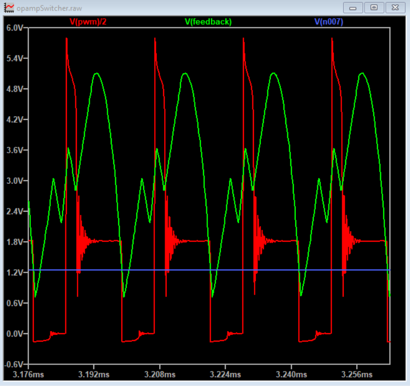
V(n007) is the voltage divider node, going into U1 minus input. V(pwm) is divided by 2 just to keep the graph more readable.
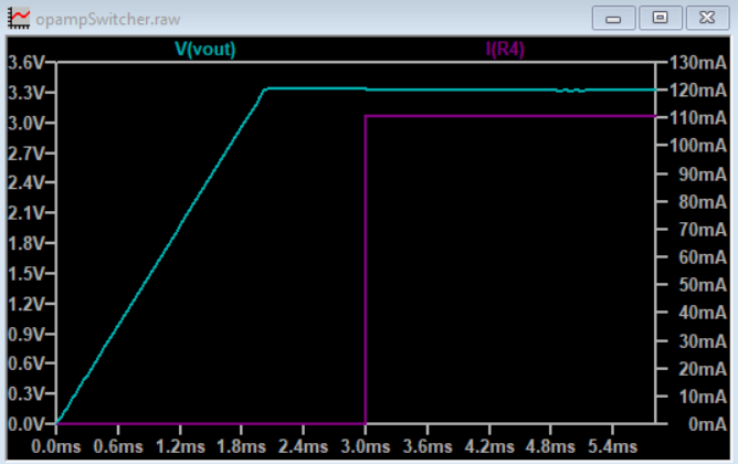
And the ultimate test, the output (does it work?)
3.3V @ 110mA
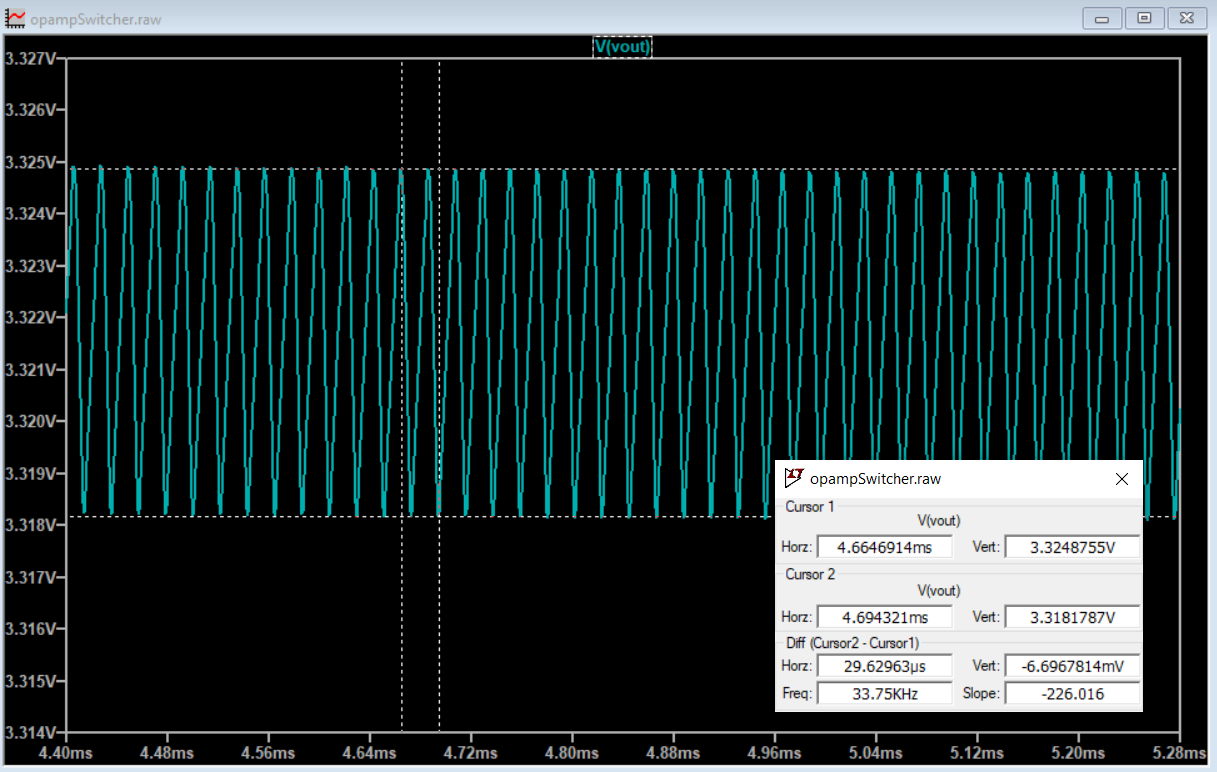
And less than 7mV of ripple:
Time to make it for real!
Discussions
Become a Hackaday.io Member
Create an account to leave a comment. Already have an account? Log In.