Rudraksha Vegad
First i would like to give a glimpse of the project here and full detailed "how to" and "problems" are explained in the "Build instructions section"
The idea is to make an analog electronic circuit using OP-amps to read specific type of thermocouple output voltage { in this project type-T } and get absolute temperature measured precisely in terms of ( 1mV/°C ) output.
Few tests will be performed to benchmark various characteristics, see how precise the circuit is performing and working of the final project.
I always love to deep dive into things which i find fascinating so in this project i have covered detailed theory and practical implementation.
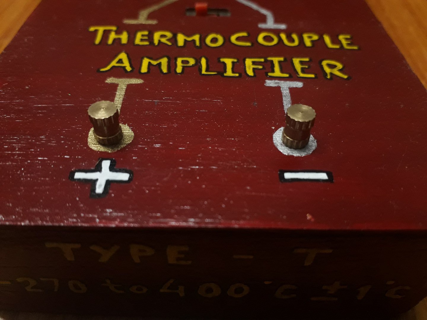
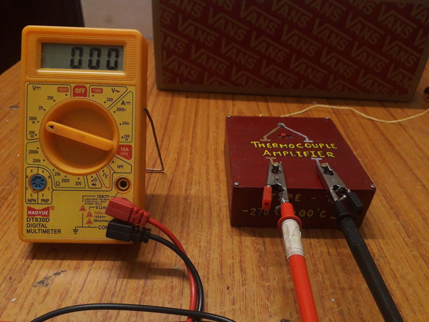
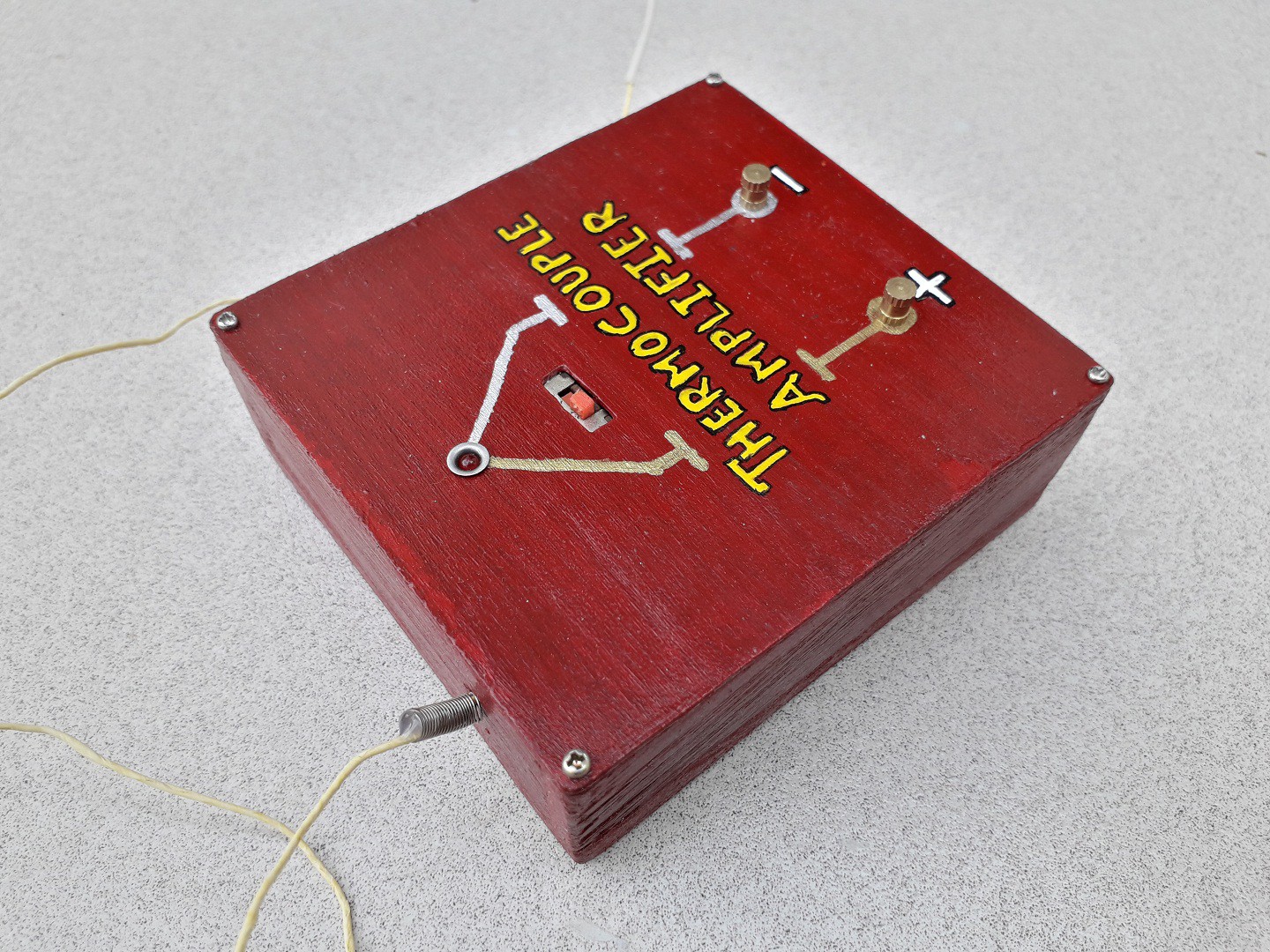
Thermocouple amplifier :

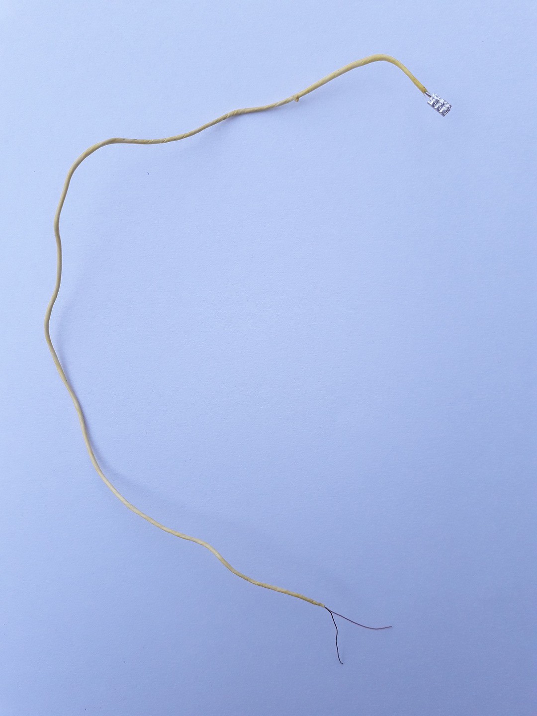
The yellow wire coming out off the box is the home made thermocouple.
The red box contains the whole analog circuit inside which processes the thermocouple's miniscule voltage and gives absolute temperature reading in terms of { 1mV/ °C } output which can be viewed on a multimeter /milivoltmeter
How to connect:
+ connects to positive probe of the multimeter and
- connects to negetive probe of the multimeter.
The multimeter needs to be set in milli-volt range to display correct temperature
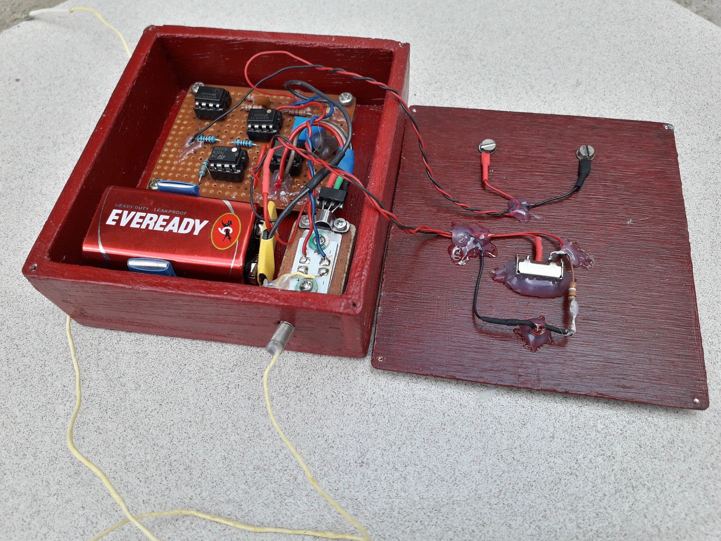
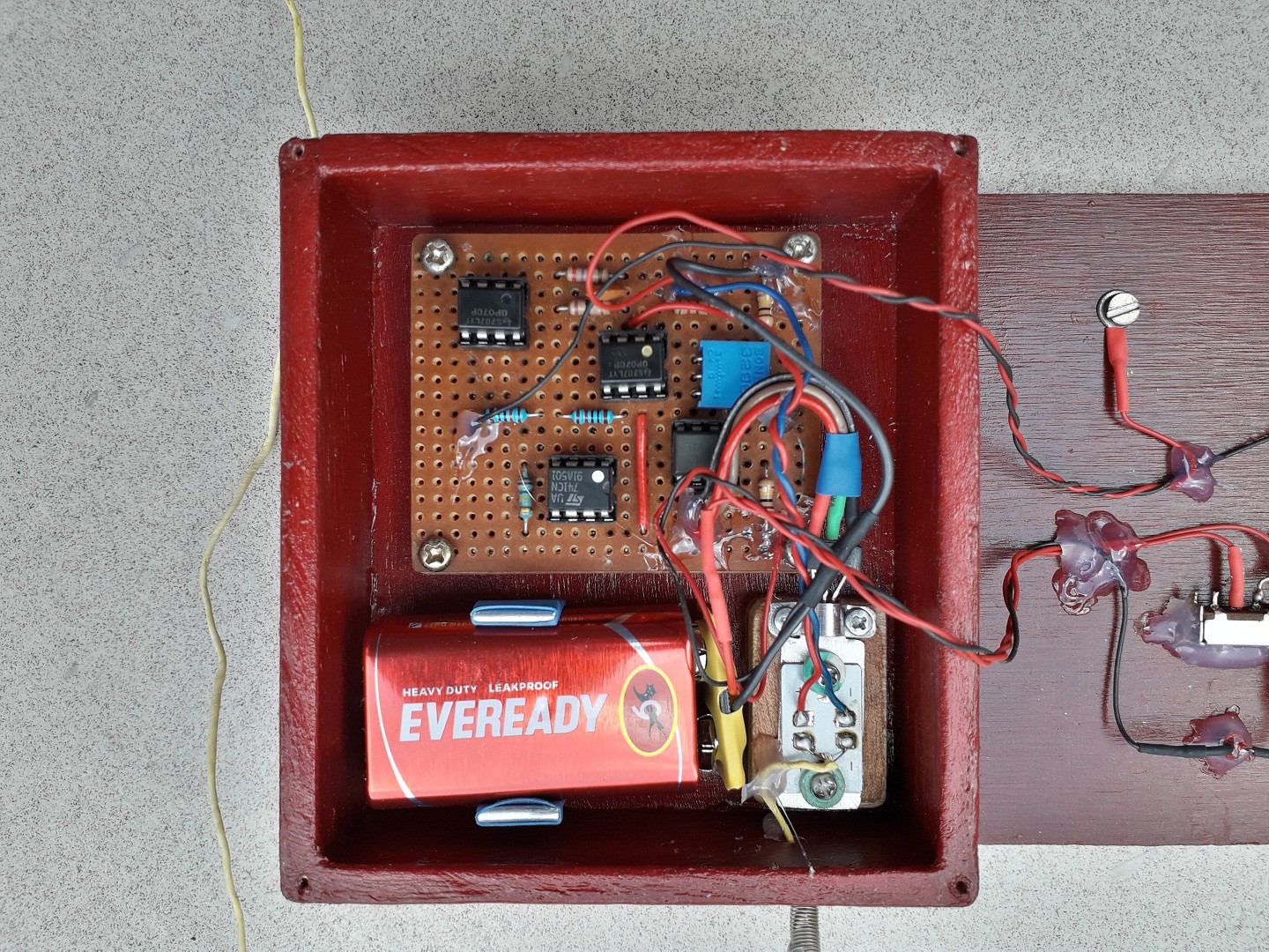
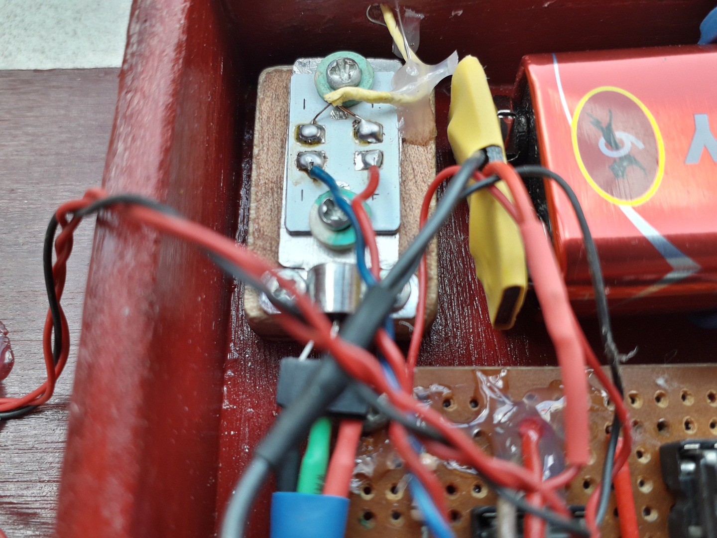
Inner view :
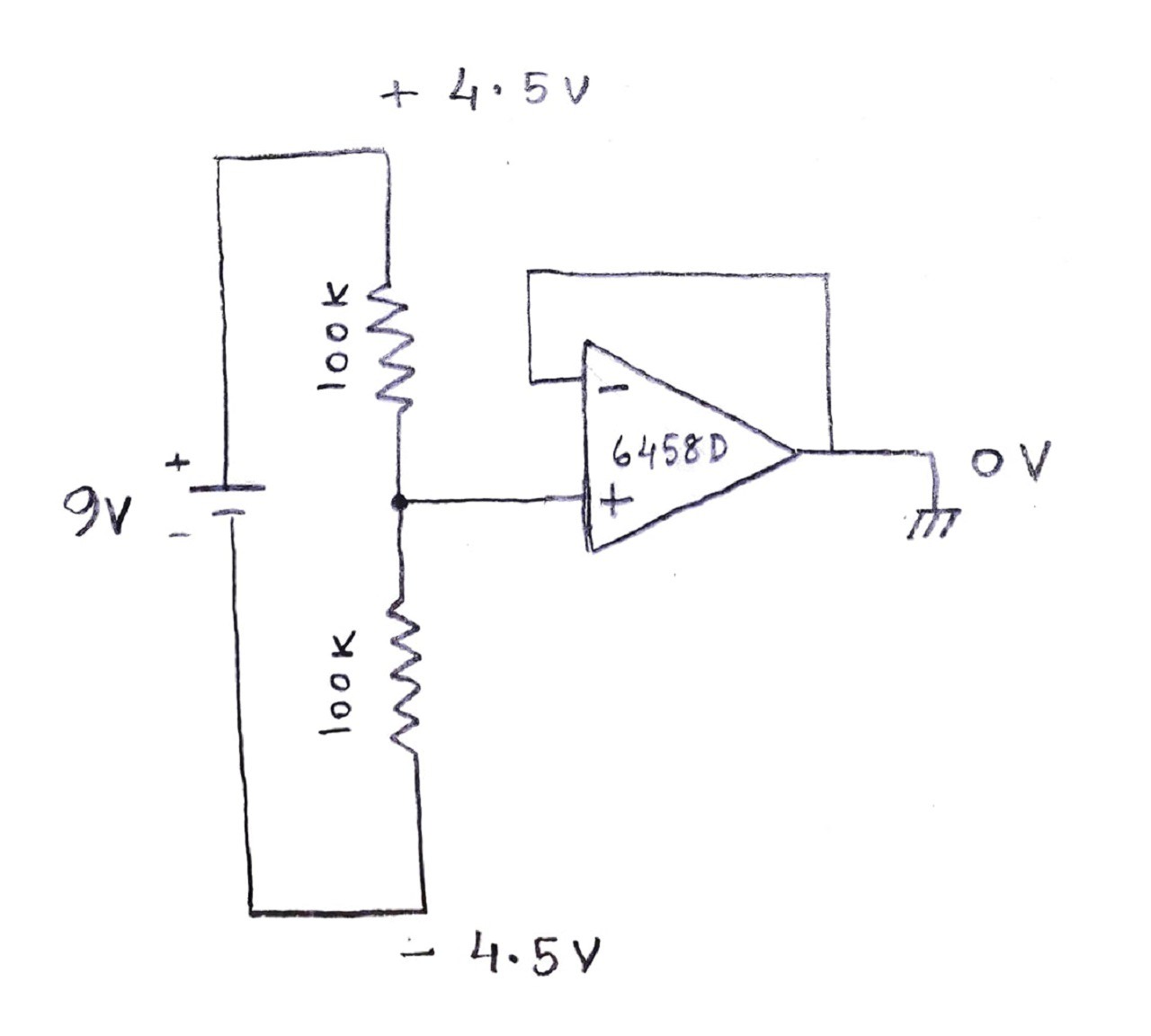
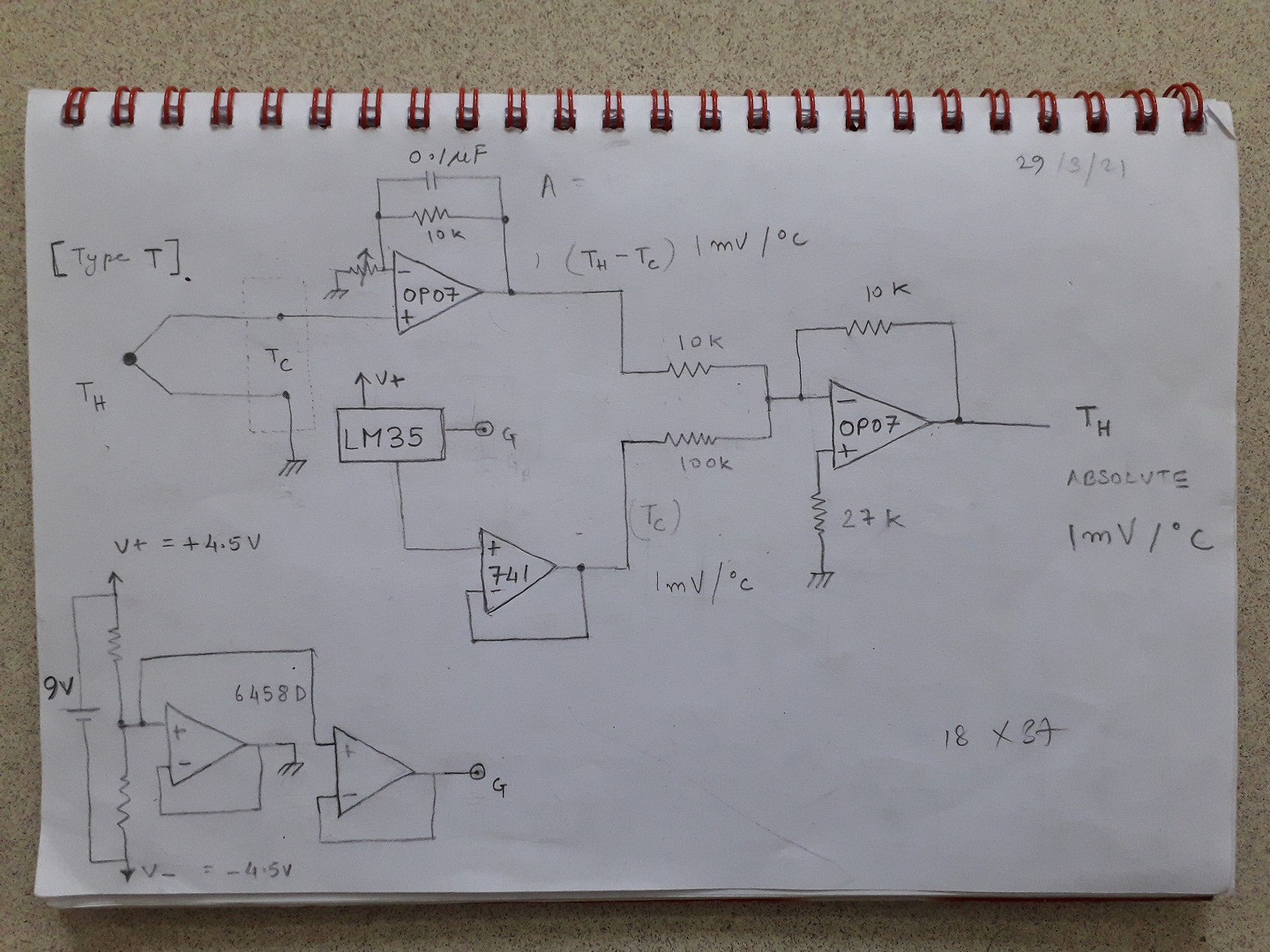
Schematic :
Following is the schematic of the complete circuit designed after experimenting on breadboard.
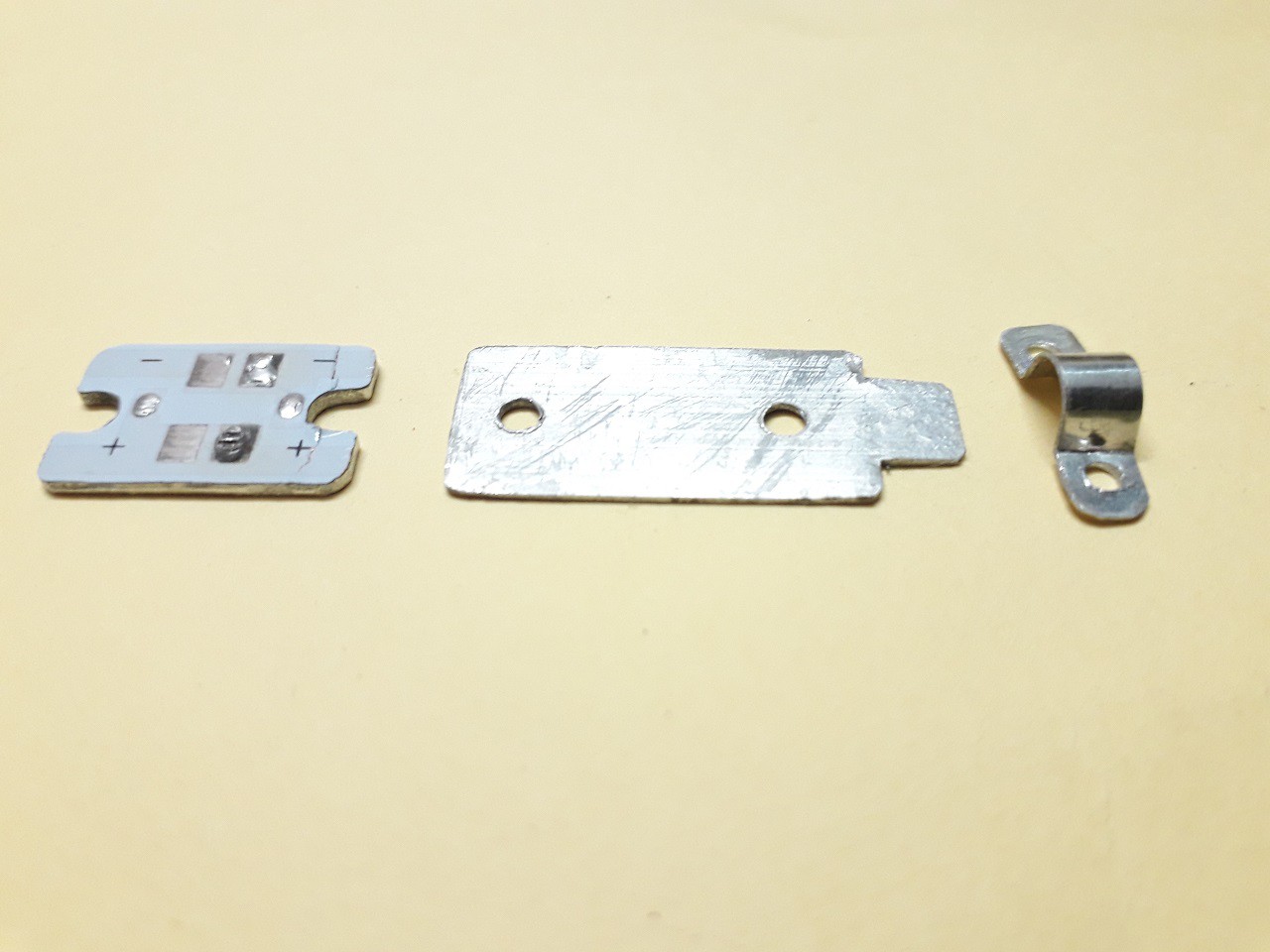
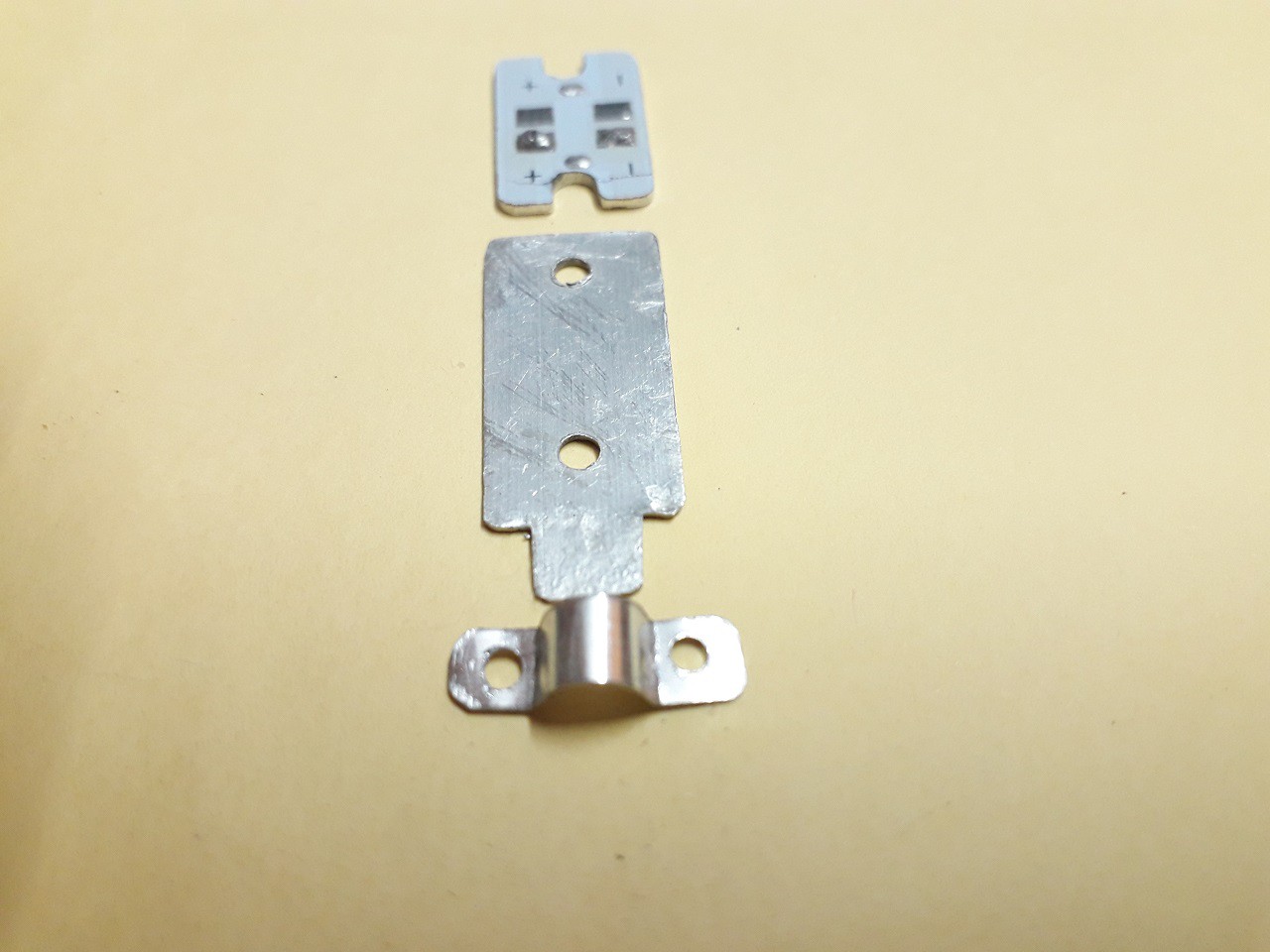
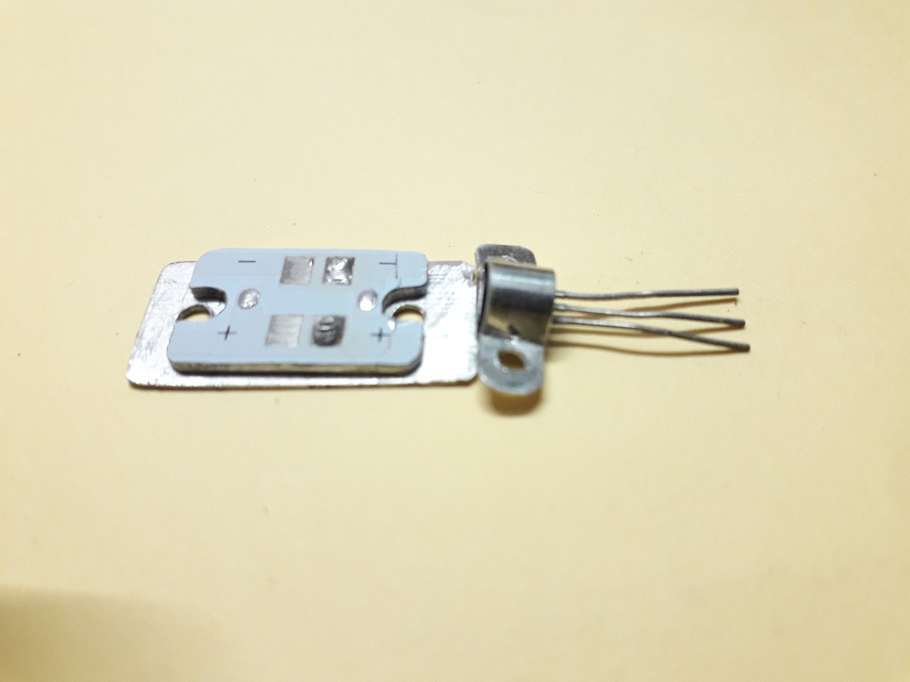
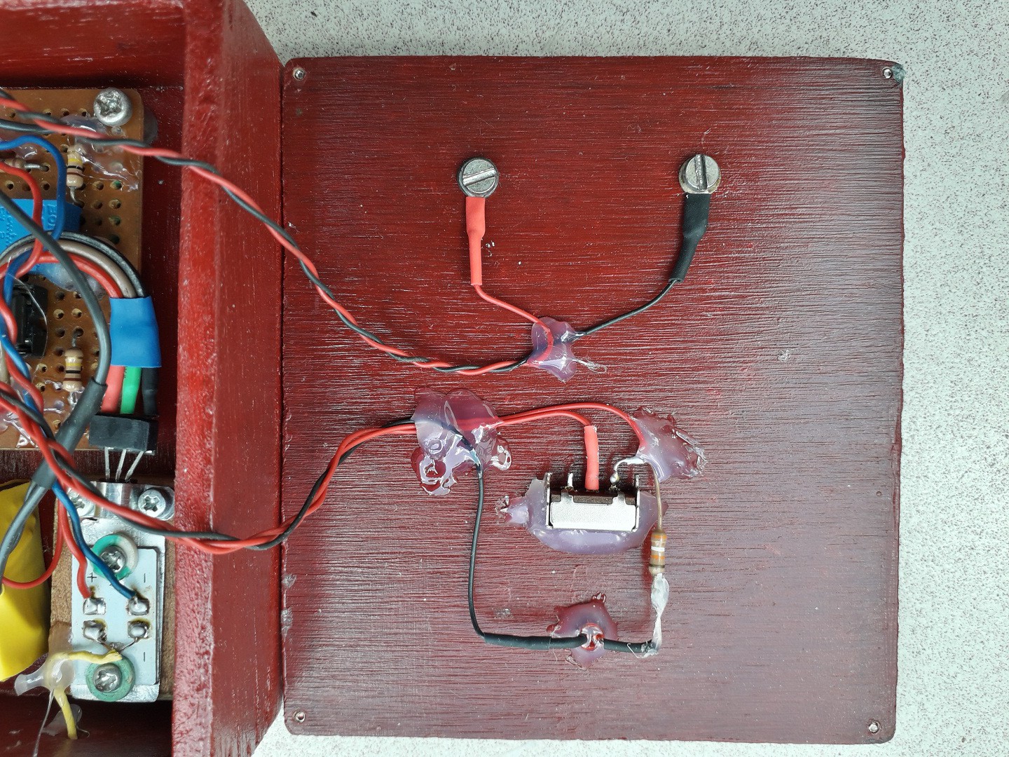
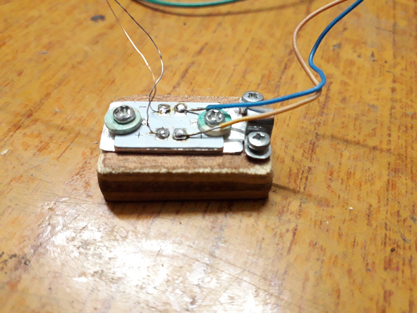
Iso-thermal Block :
This is the part which monitors temperature of the cold junction which is necessary factor to compensate for the cold junction.
This block couples the cold junctions THERMALLY but isolates ELECTRICALLY.
(detailed explanation is in the theory and instructions section)
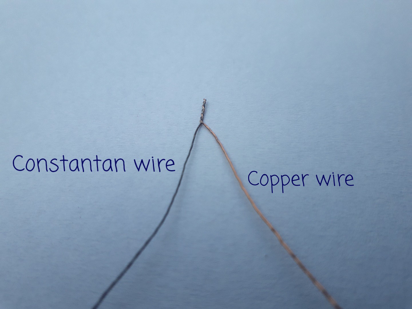
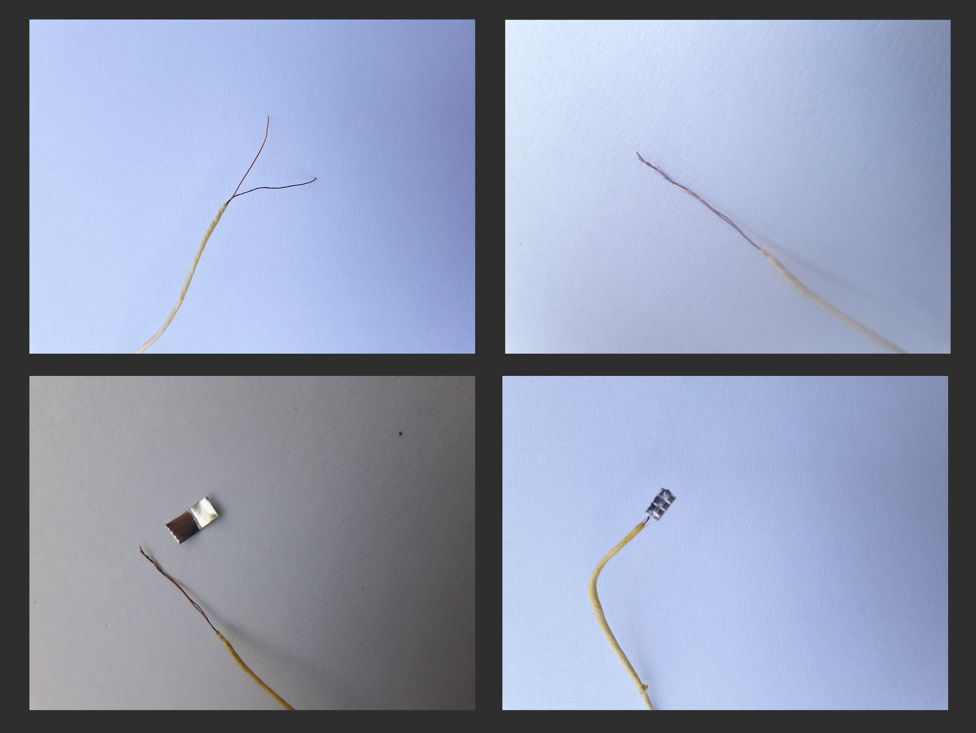
Home made Thermocouple (T - type) :
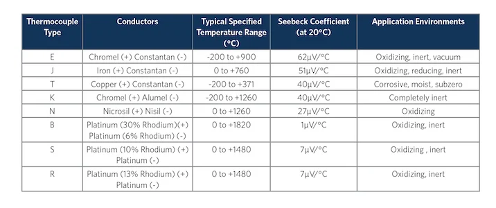
For the thermocouple i chose to make T- type thermocouple because material for making it were easy to find.
T- type thermocouple uses Constantan and Copper combination.
(detailed explanation is in the instructions section)

The measuring accuracy is ±1 °C. This also fits in the actual accuracy of the industrial T type thermocouple. and measuring range is -200°C to +400°C .
Theory :
I won’t go very deep in detail theory, but will stick more with practical implementation
A thermocouple consists of two wires (say metal A and metal B) which are joined at one end the HOT end that is the end from which temperature is being measured and the other end is called the COLD end. When these two junctions are in temperature difference, potential difference builds between the open ends as shown in the following figure.
Thermocouples work on the principle of Seebeck effect.
Thus thermocouple acts like a transducer and can be used as temperature sensor.
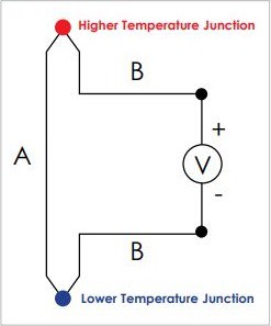
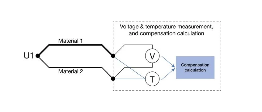
The output voltage is differential i.e. , V out ∝ { T hot - T cold }
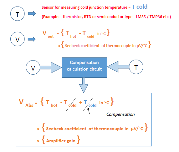
Voltage due to T cold needs to be eliminated. This is called compensation since we don't want voltage due to T cold.
Output voltage without any amplifier will be:
Thot = Temperature of the hot junction
Tcold = Temperature of the cold junction
V out = { T hot - T cold } x { Seebeck coefficient }
Types of Thermocouples:
There are various types of Thermocouples with different ranges and dedicated applications
Simplified arrangement of thermocouple:
Typically In domestic and industrial applications a slight variation of the thermocouple is used. Instead of two separate junctions as shown in previous figures, connecting wires are treated as cold (reference junction) which are isothermally coupled.
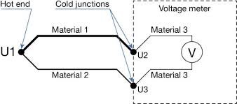
This type of arrangement is much more practical, easier and eliminates unwanted junctions ( junctions which behave as unwanted thermocouples ). which causes error in the output voltage.
we know : V out ∝ { Thot - Tcold }
it applies here also, V out ∝ { Tu1 - T(u2 +u3) }
we need to compensate for the voltage...
Read more »