 Clyne
ClyneThe assembled PCBs have finally arrived, and after some testing and tweaking have proven to be good successors to the previous design. There is a ton to go over for the bring-up process; I'll share some initial observations and testing here, and then in the following log take a deep dive into validating the input and output signal paths.
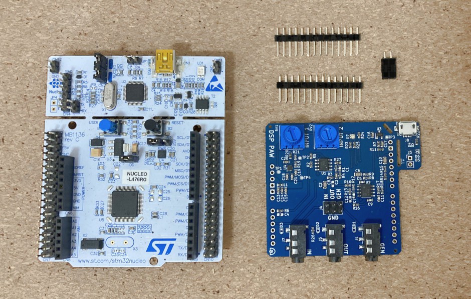
Although the 3D renders were of green PCBs, I chose to stick to the blue color that the previous iteration used. It compliments the NUCLEO deveopment board better.
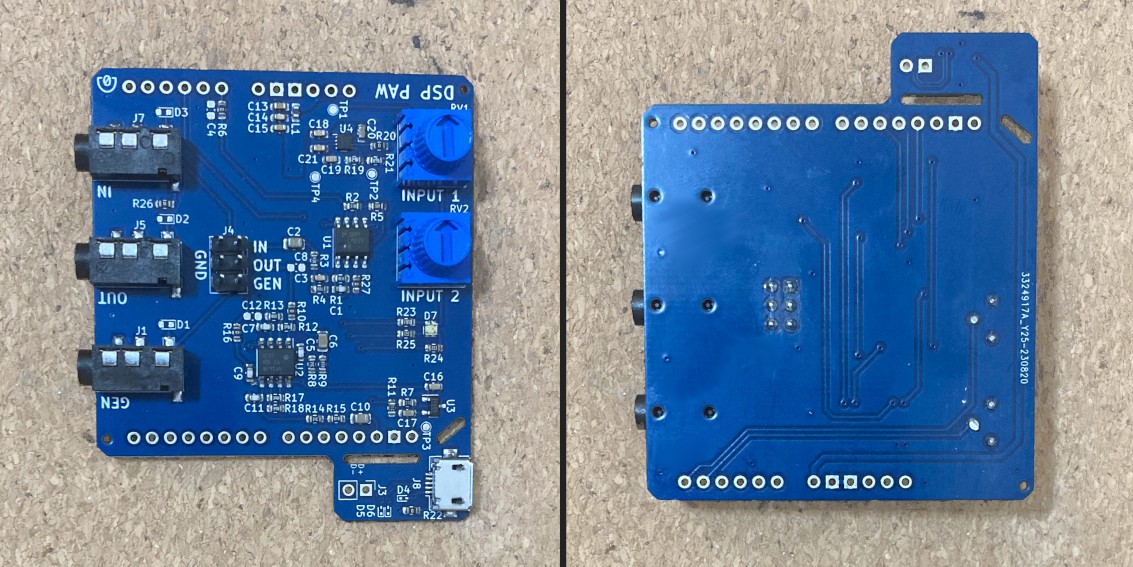
The USB breakaway came out better than I expected, and feels sturdy when a cable is attached. There's only one issue with the board that's immediately noticable: the protection diodes are missing.
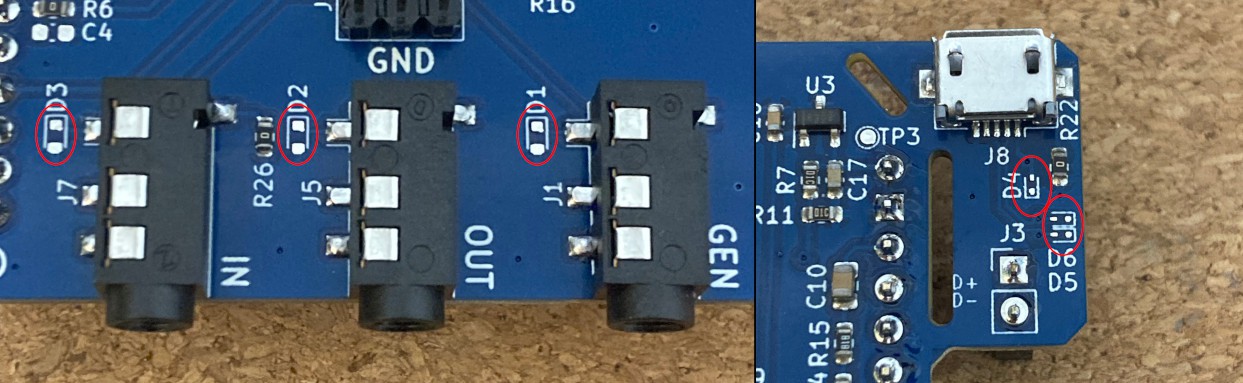
I went back to my order confirmation, and oddly enough the BOM used for assembly did not include any diode part numbers. I double-check the original BOM next to ensure my sanity, and...
| Reference | Part Number |
| D1,D2,D3 | ESD5Z2.5T1G |
| D4,D5,D6 | DF2B7AFS,L3M |
...we realize that the BOM exports as a comma-separated file (.csv). The comma in D4-D6's part number probably caused an error and made the ordering page drop that row. I guess that a similar issue exists for the part number with a period in it. Fortunately, these parts are not essential to the design, though it's a shame that this wasn't caught.
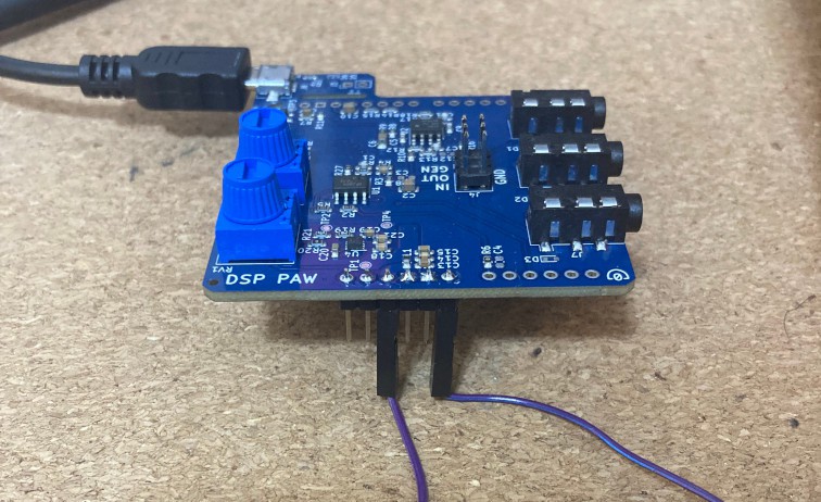
Anyways, we now move on to powering the board up and making sure the power regulation is correct and stable. It's best to test this before risking the connection to the microcontroller board, so I soldered on a little header for the power pins and plugged in the USB cable:
Nothing put out heat or smoke, which is good. I used a multimeter to check the power supply test points: ground, +5V, -5V, and the 2.048V voltage reference -- everything looks good!
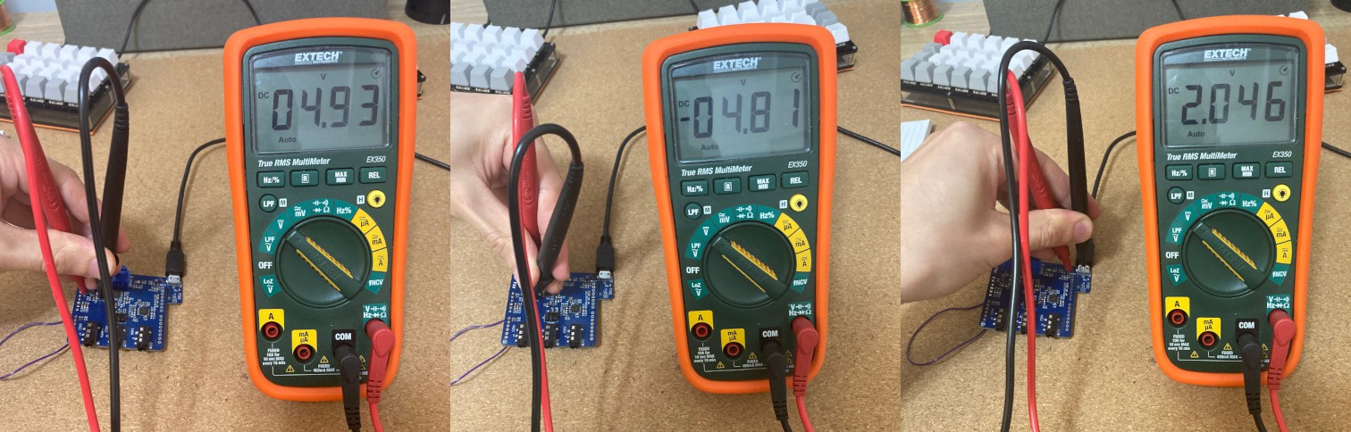
The USB cable does not supply a perfect +5V, but that doesn't really matter. The opamps only need +/- 2V to properly handle the analog signals, so anything beyond that minimu should work well.
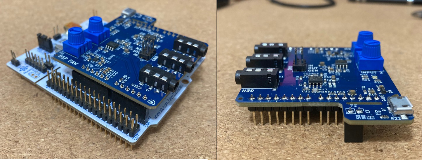
At this point, it should be safe to fully connect the new add-on board to the NUCLEO and test the inputs and outputs completely. All that is needed is a pair of 14-pin male headers (to break apart and fill the Arduino connector), and a 2-pin female header to connect to the microcontroller's USB data pins.
By sticking the headers into the NUCLEO board, I could solder them onto the add-on board with everything lined up and fitting:
The input and output circuits are certainly more complex than the power supplies, and that'll show in the amount of testing and adjusting they needed. Stay tuned...
Discussions
Become a Hackaday.io Member
Create an account to leave a comment. Already have an account? Log In.