 Clyne
ClyneWith the input signal circuit figured out, it's time to move on to the output circuits. There are two, one for the algorithm output and another for the signal generator, though both use the same exact circuit. This means we can just test the signal output and copy any necessary changes over to the generator circuit.
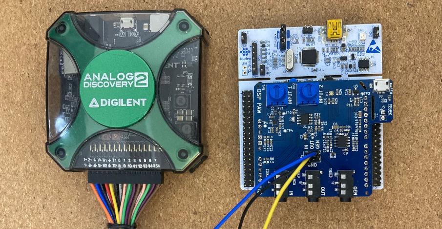
For these tests, I used the Analog Discovery 2 again to provide an input signal and oscillator probe for the signal output pin. The development board will be used with the DSP PAW user interface to execute a "pass-through" algorithm that simply outputs the received signal. If all goes well, the oscilloscope will show matching input and output signals (though the microcontroller's sampling rate will introduce some visible steps in the output voltage).
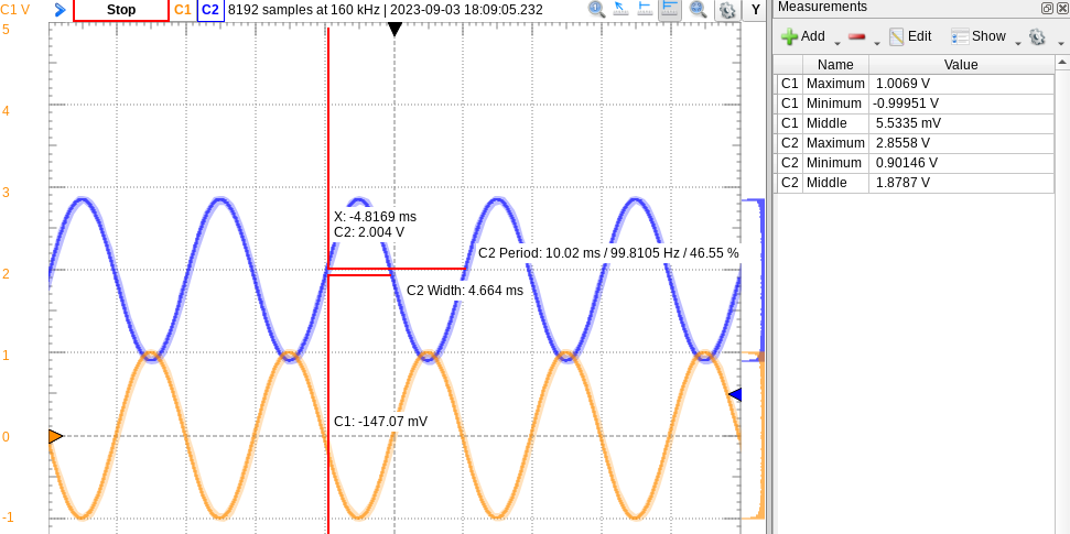
My first test used an easy 1V, 100 Hz sine wave, shown below. The output signal (blue) is surprisingly clean, though it's offset by nearly one Volt. There is a DC blocking capacitor directly on the microcontroller's DAC output, so the offset should not be there...
The signal may appear to be inverted, but that's just coincidential. Processing the signal introduces latency that can create this offset; the opamp's filtering may also cause a change in signal phase.
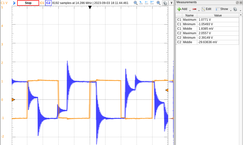
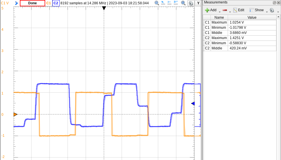
We'll take care of the offset soon, but first I was skeptical of the output's clean performance. I changed the input signal to a square wave, creating impulses that had a better chance of causing noise or oscillations.
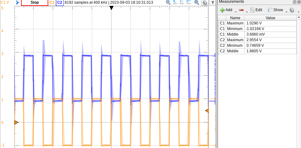
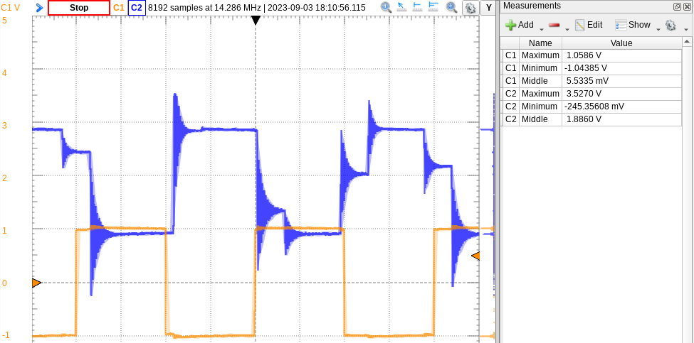
Those shaded blue areas are spots of noise caught by the oscilloscope. From here, we increase the input signal frequency and zoom in to see some pretty nasty impulses (see below). The output signal is not perfectly matched to the input, but that is just a result of our limited sampling rate.
To fix up this output, we'll go back to the incorrect offset first and then handle the impulse response.
Output signal offset
Again, we have a DC-blocking capacitor at the beginning of the output circuit, so any offsets should get absorbed and leave the signal centered at 0V. I took a probe to both sides of this capacitor: the microcontroller-side of course had the DAC output with its 1V offset, but when I switched to the other end of the capacitor, the signal began making its way down to 0V just as we wanted.
It turns out the capacitor needs some kind of minimum load on it (like an oscilloscope probe) to allow its charge to settle the output at 0V. Further testing found that a 100 kOhm resistor could do the same trick, and the board may be redesigned to accommodate one.
The circuit's response to offset is quick now, and fairly accurate:
Fixing impulse oscillation
Now it's time to clean up the signal. The strange thing about this issue is that the chosen filter design, a Sallen-Key Bessel filter, should not be creating any overshoot at all. This led me back to the filter design application note I worked off of, reviewing the design process with the circuit on the add-on board.
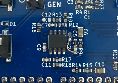
...and something came up. Here is a side-by-side picture of the board's circuit (left) and the application note's design (right):
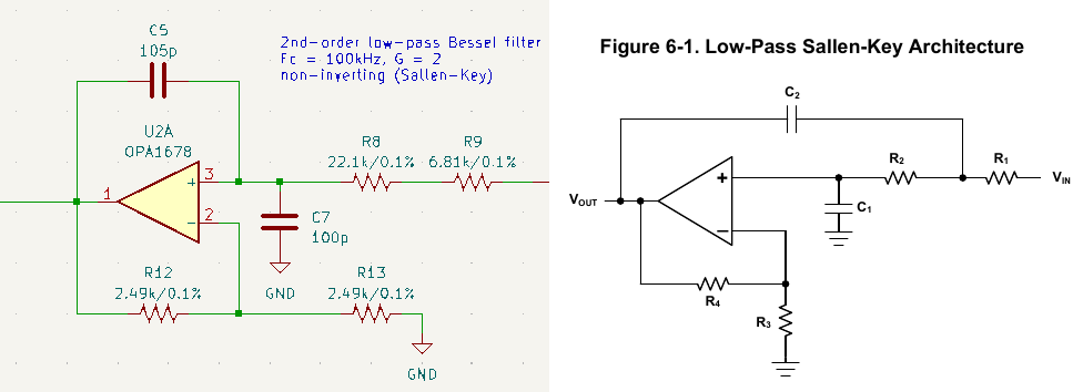
These are not the same circuit, ugh. I attached the feedback capacitor (C5/C2) to the opamp's non-inverting input, instead of between the two input resistors. I have strong confidence that this is our problem.
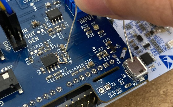
To test this, I removed C5 from its pads and soldered one end of the cap to R8 (where R8 connects to R9). I used a small enamel-coated wire to get the other end of the capacitor re-connected to the opamp's output through its pad on C5.
Now we return to the oscilloscope and hope for good results...
Perfect! Now we've learned that impropely-designed circuits will lead to bad results :)
I'll go ahead and edit the add-on board's schematic and layout to include this fix, so that future boards are wired correctly. Copying this fix to the signal generator would be worse, with its feedback cap (C9) far away from the two involved resistors (R14 and R15). I'll at least make the edit to one board to confirm the circuit is okay otherwise.
Frequency response and noise analysis
With the circuit fixed, we'll do a frequency sweep just as we did for the input signal path to confirm that signals within our sampling range are not too diminished.
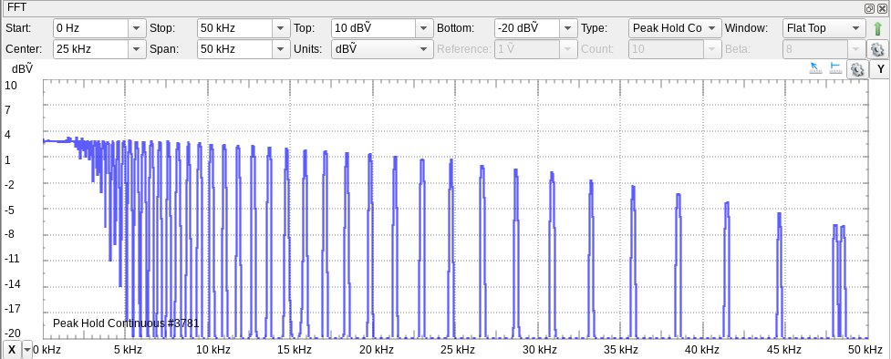
The decline toward higher frequencies is more steep, but that can be expected with a sampling rate of 96 kHz. At just 48 kHz, the microcontroller will see the input sine wave as a square wave since it will only capture two samples per period. The output signal stays above -3dB compared to its 0 Hz strength until around 25 kHz, allowing us to work with audio signals well. This range of performance is definitely adequate for educational work.
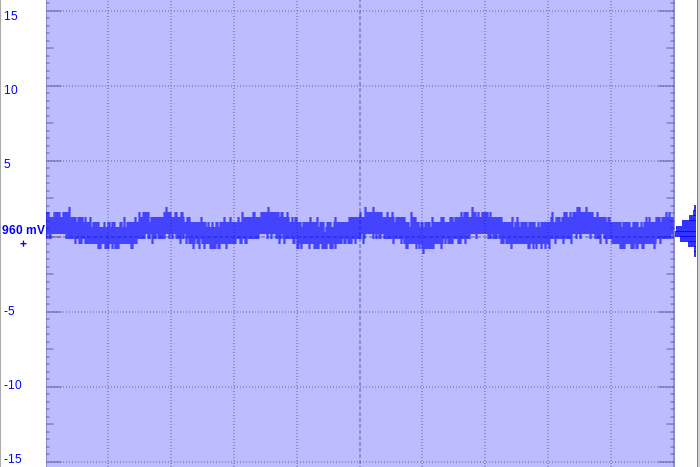
Finally, I took some close-up captures of the output of the input and output circuits to check on signal noise levels. The output path was tested first, proving itself to reliably reproduce signals within +/- 10mV:
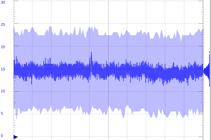
The input signal seems to perform well too, but the shaded blue region is much larger. This indicates the presence of some high-frequency noise -- later, I might try to eliminate this by implementing the additional low-pass filter that I left board footprints for. This noise measured to be 750 kHz or greater.
Discussions
Become a Hackaday.io Member
Create an account to leave a comment. Already have an account? Log In.