 M. Bindhammer
Introduction
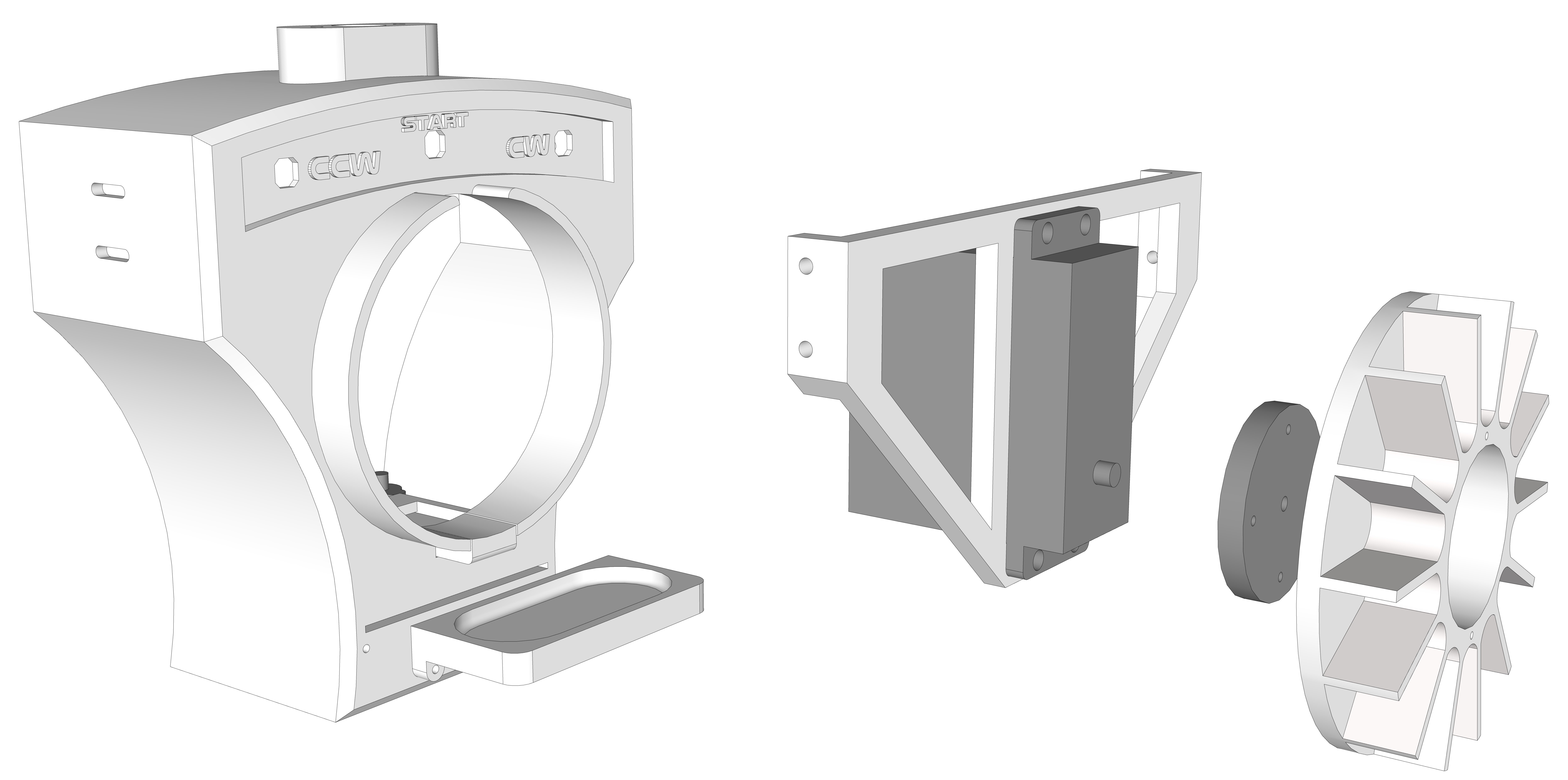
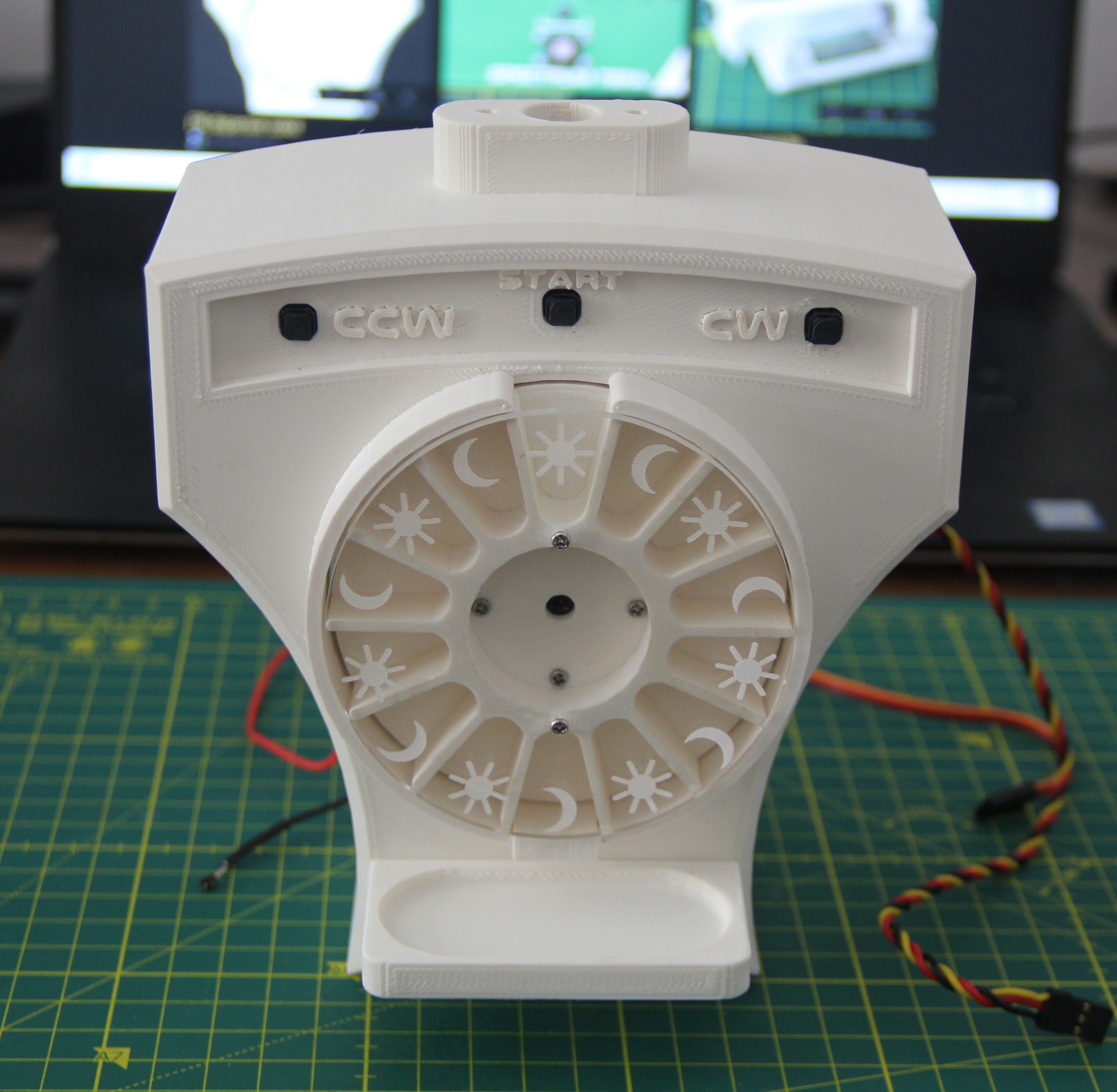
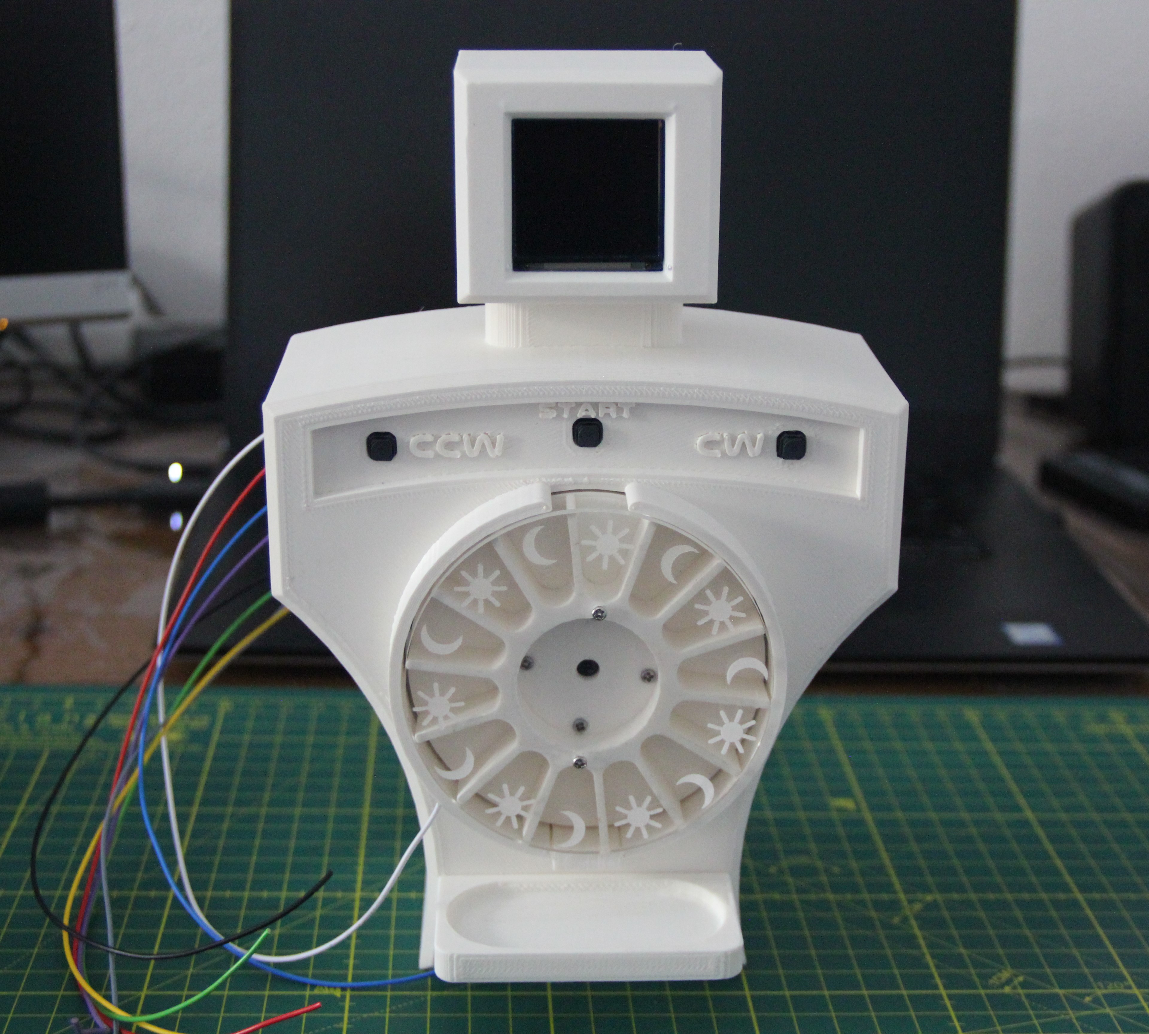
The heart of the robot is a drum divided into 14 chambers. A Hitec HS-785 HB winch servo turns the drum. The servo is completely overkill in terms of torque, but it supports a true 360-degree rotation via the PWM signal. A second servo opens a flap so that the corresponding pills fall into a small catch basin. A touch sensor is integrated into the catch basin so that the robot recognizes whether the patient has taken the pills. The robot will also be able to speak, and the head of the robot will be equipped with a TFT display. For more details, see the Speech Synthesis and PCBs log.
Building the robot
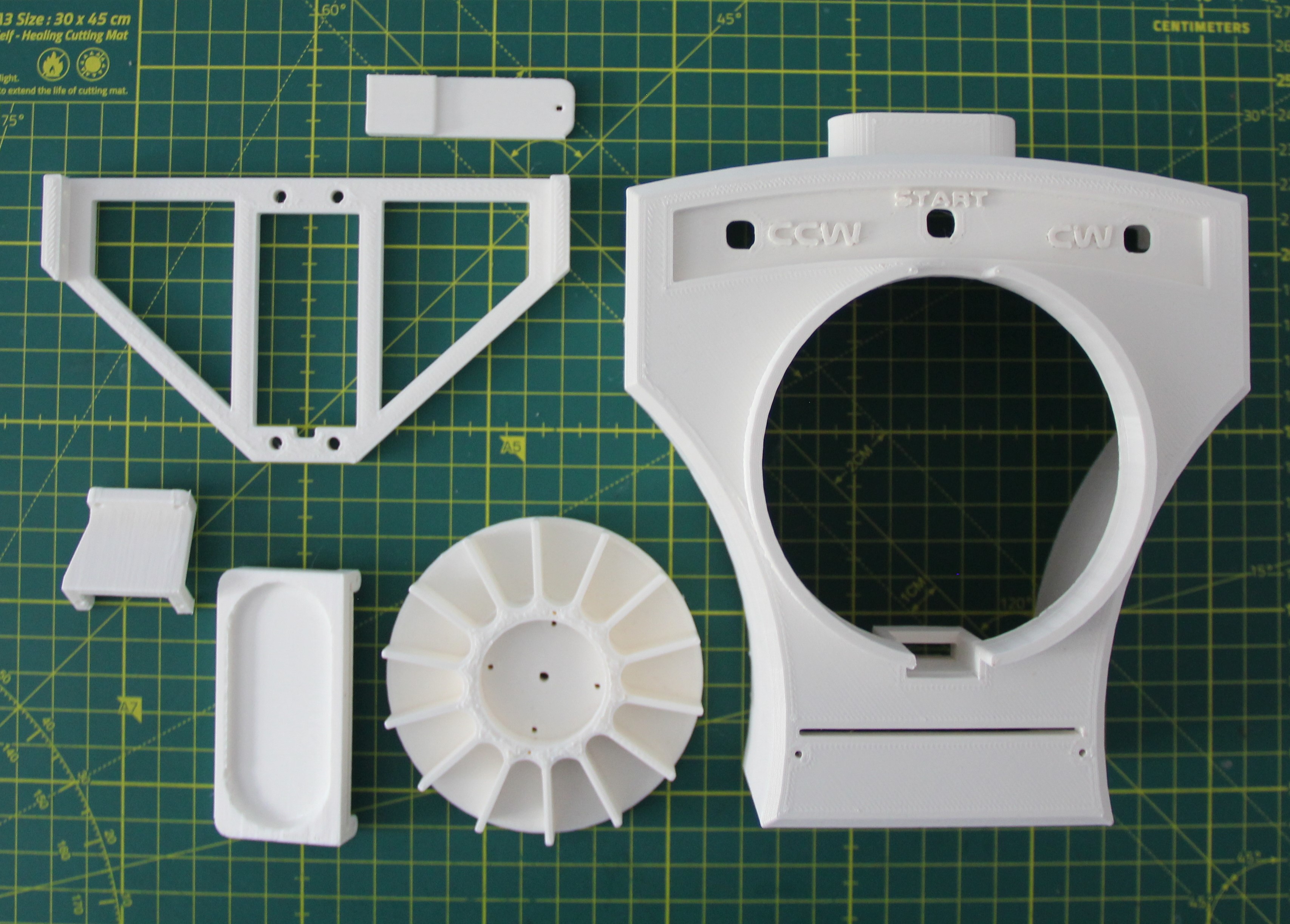
The first batch of parts have been printed in ABS with a 50 to 80% infill and came out ok.
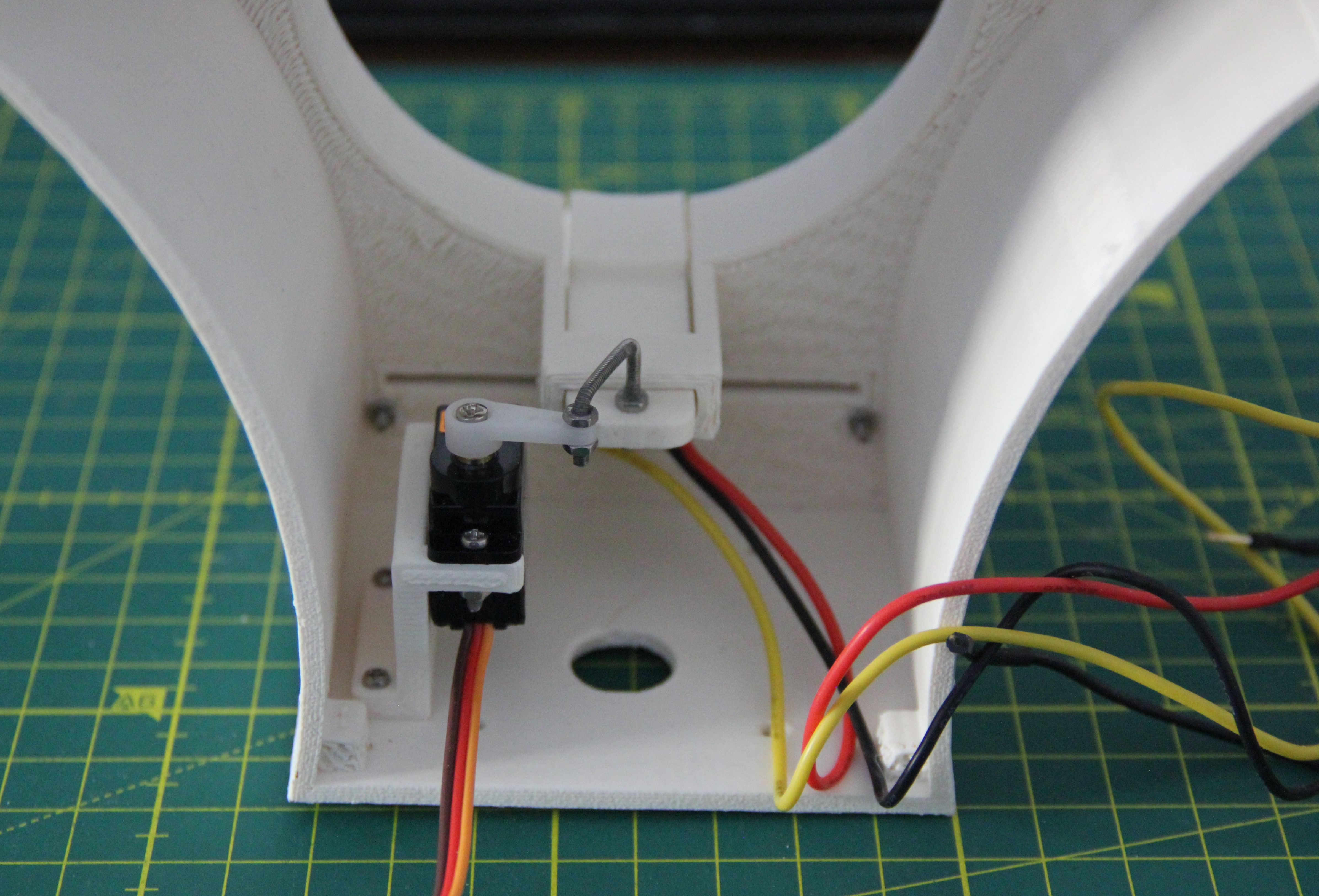
First, the touch sensor and push button PCB were installed, then the micro servo to operate the slider for pill dispensing.
The HS-785 HB servo for rotating the drum was screwed to the bracket with four M4 X 12 mm screws, then fitted into the robot housing. The four slotted holes in the housing to mount the bracket make it easy to align the servo precisely.
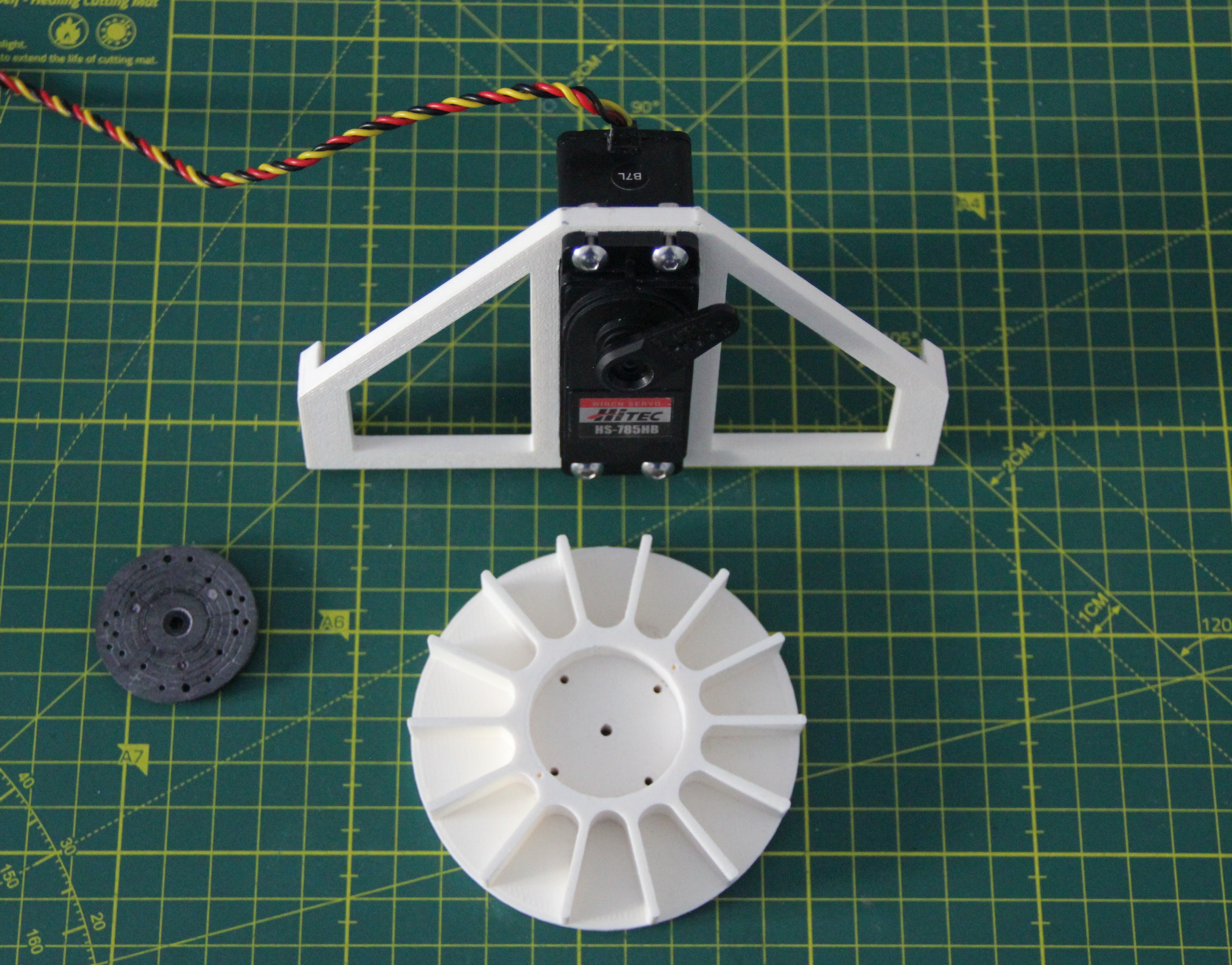
In the next step, the servo horn was screwed to the drum using four M2 x 12mm screws, then placed on the main axis of the servo and secured using the screw supplied with the servo. Finally, the laser-cut acrylic disk was attached using two M2.2 x 8mm self-tapping screws.
The HS-785 HB servo rotates 2826° at a pulse width of 600-2400µs and 630° at a pulse width of 1500-1900µs. This gives us a maximum resolution of 1.57°. Not very precise, but precise enough for our purpose.
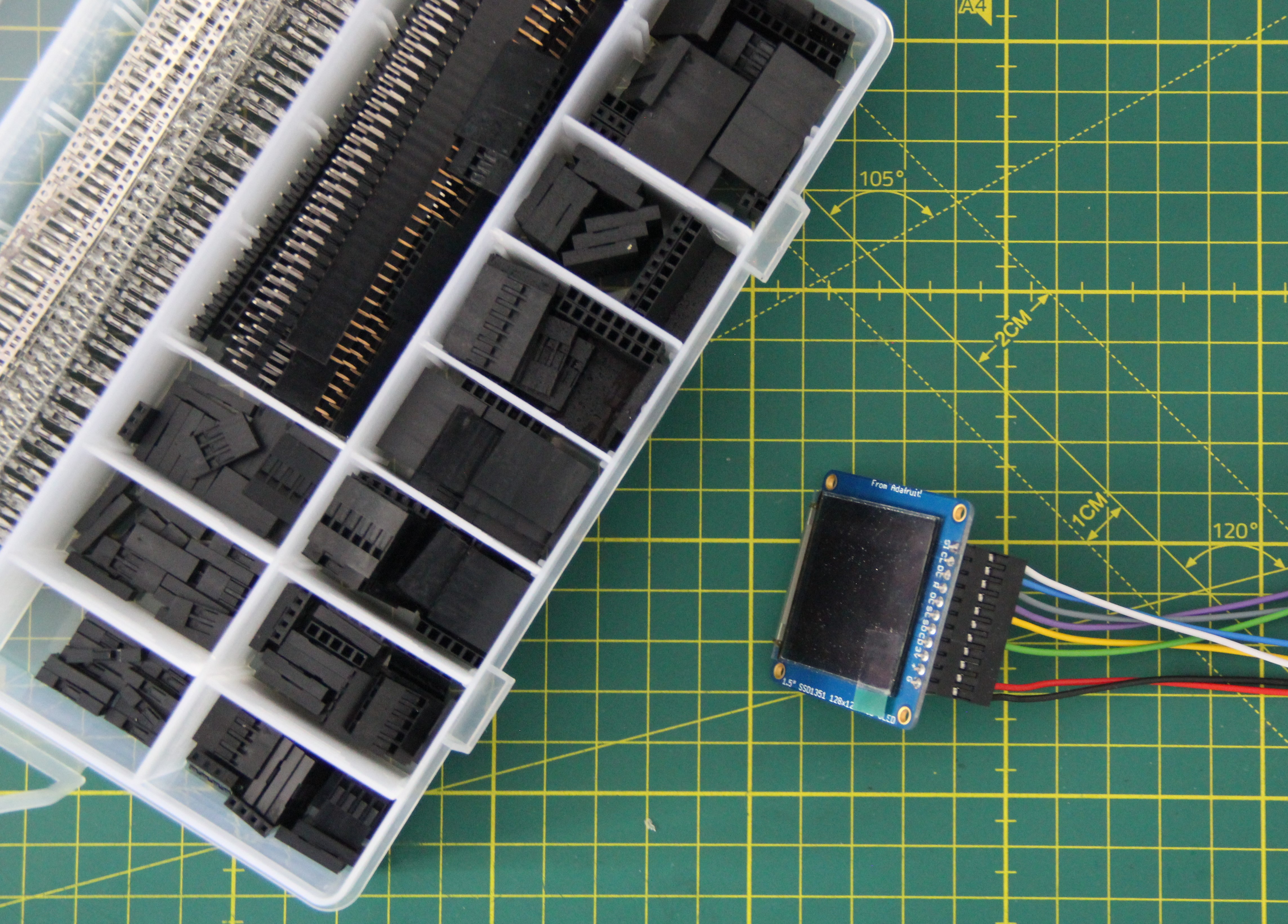
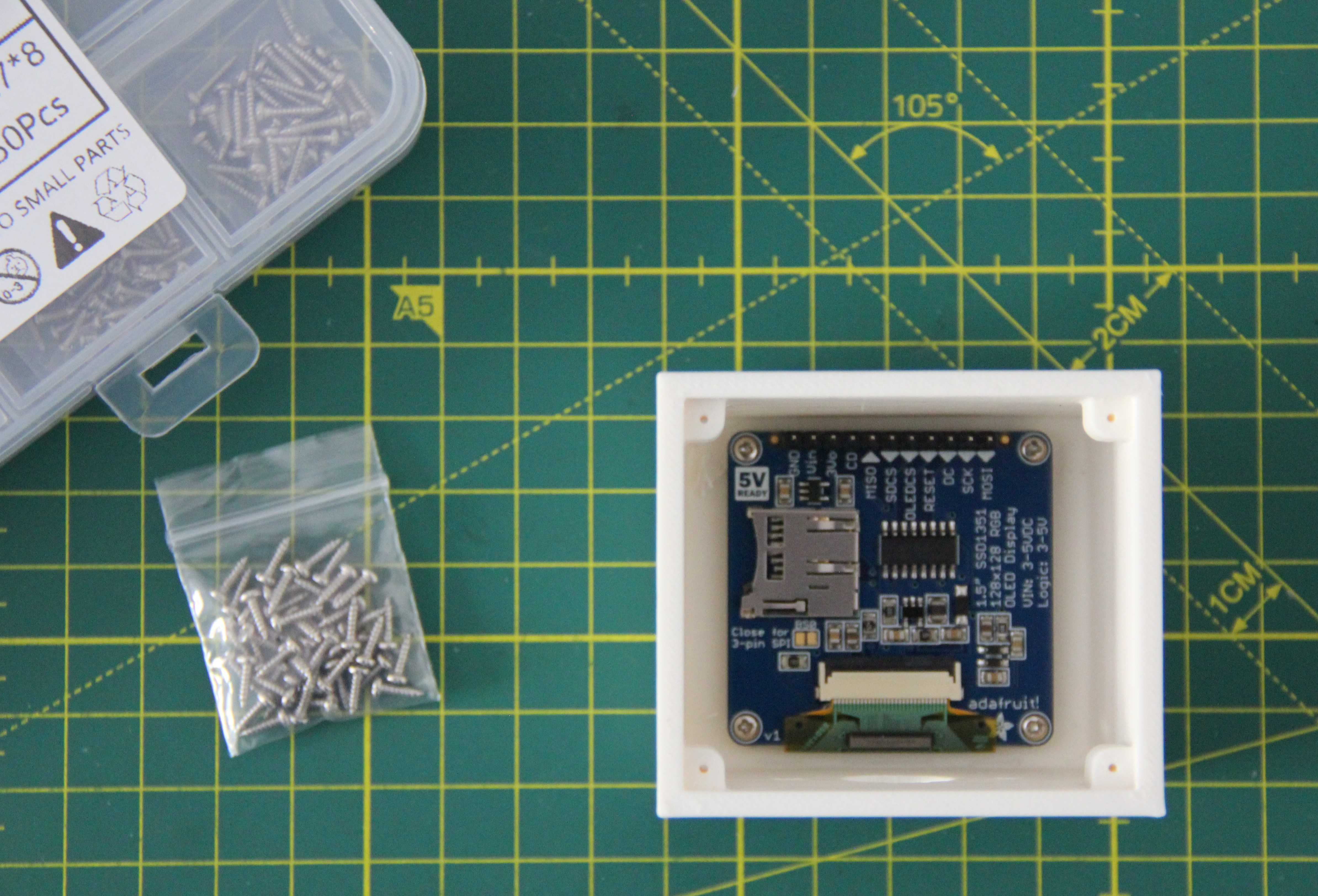
Using the kit seen on the left, I made custom cable connectors for the OLED. You don't need any special tool for this, just a small pair of pliers. I don't just clamp the wire to the insert, but solder the wire to the insert, which gives a much more reliable connection.
After I made some adjustments, the second batch came out of the printer quite nicely.
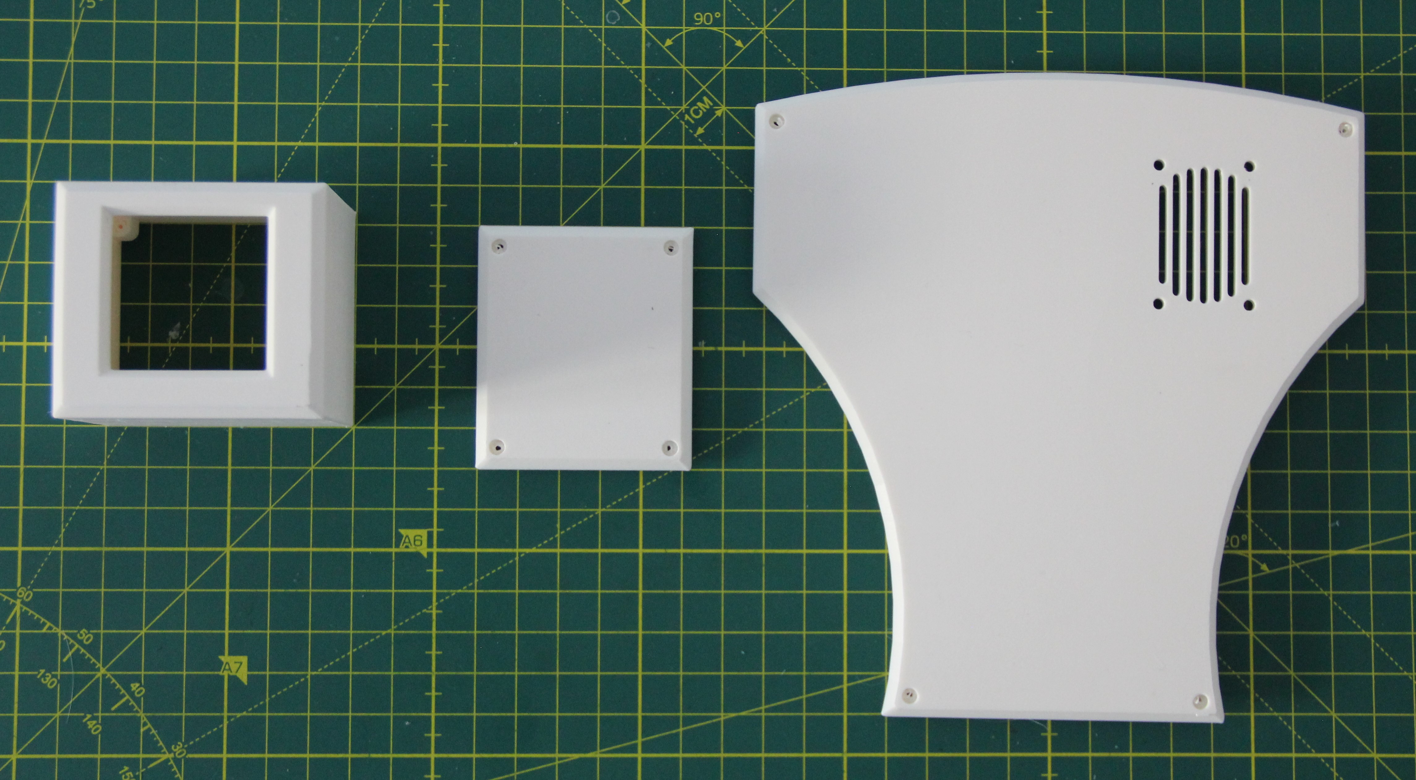
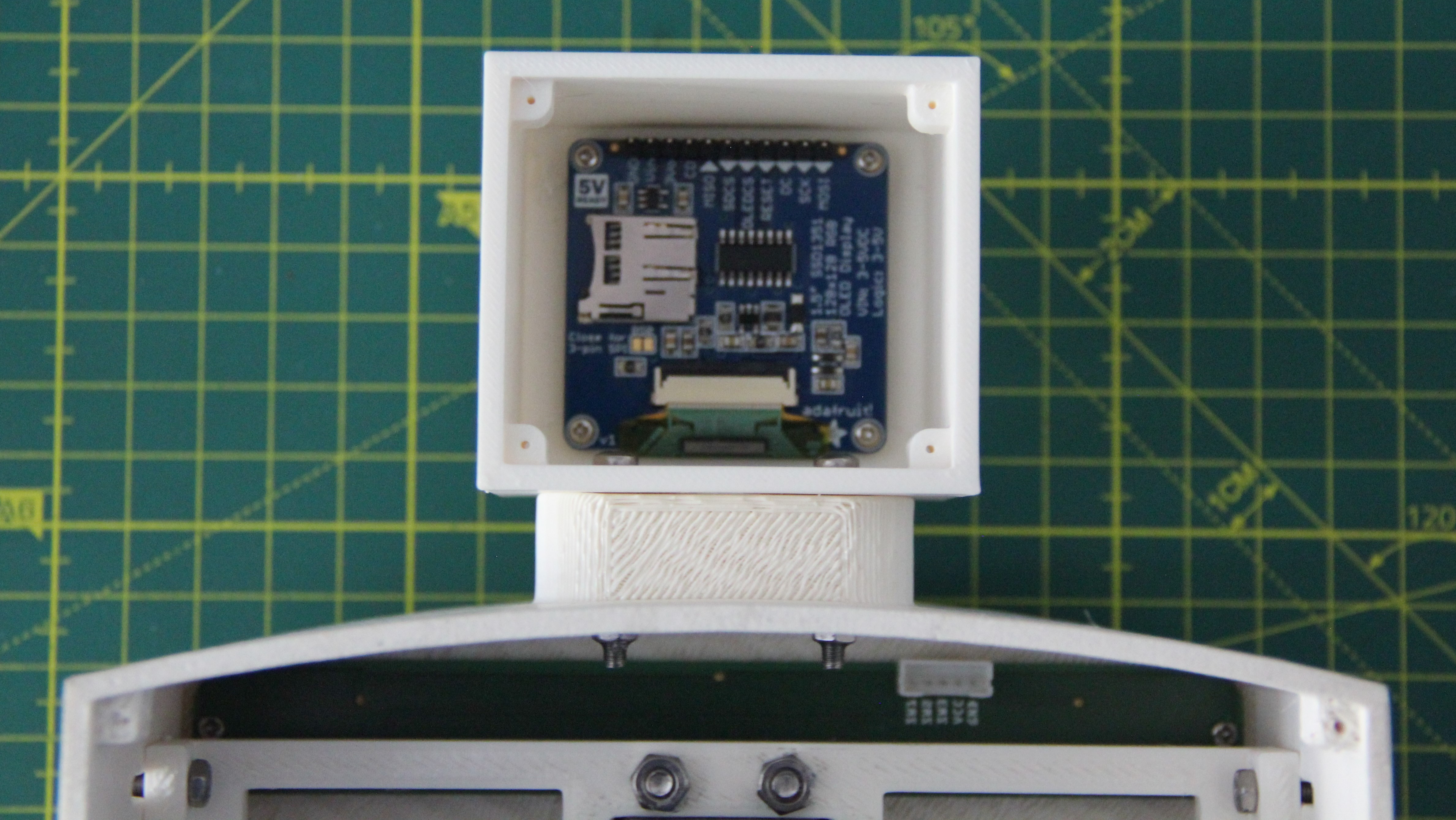
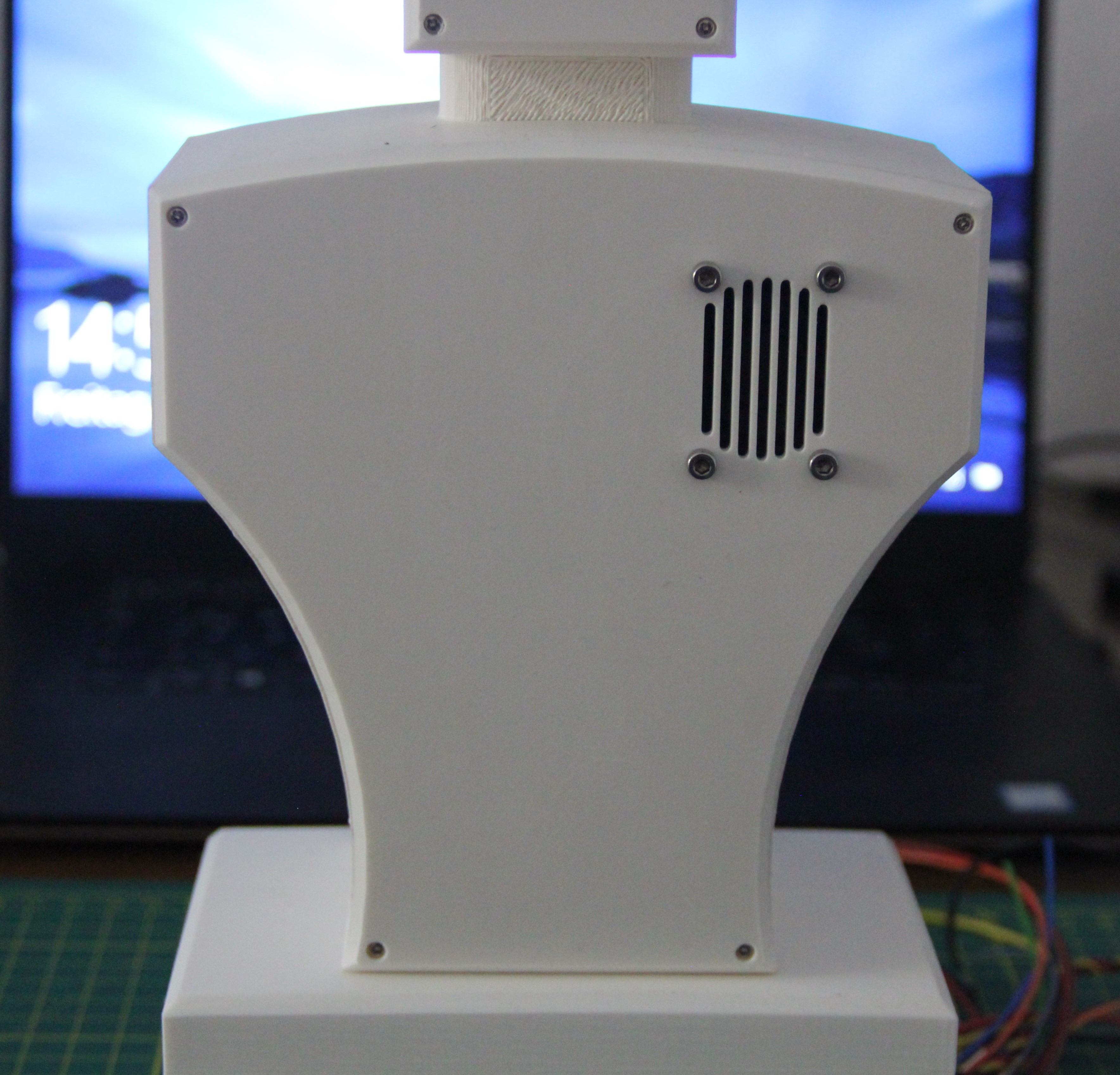
THE OLED was screwed into the head of the robot using four M1.7 x 6mm self-tapping stainless steel screws.
The head was then attached to the upper body with two M3 x 25 mm stainless steel screws and nuts.
After wiring the OLED, the cover was attached to the back of the head with four M1.7 x 8mm self-tapping stainless steel screws.
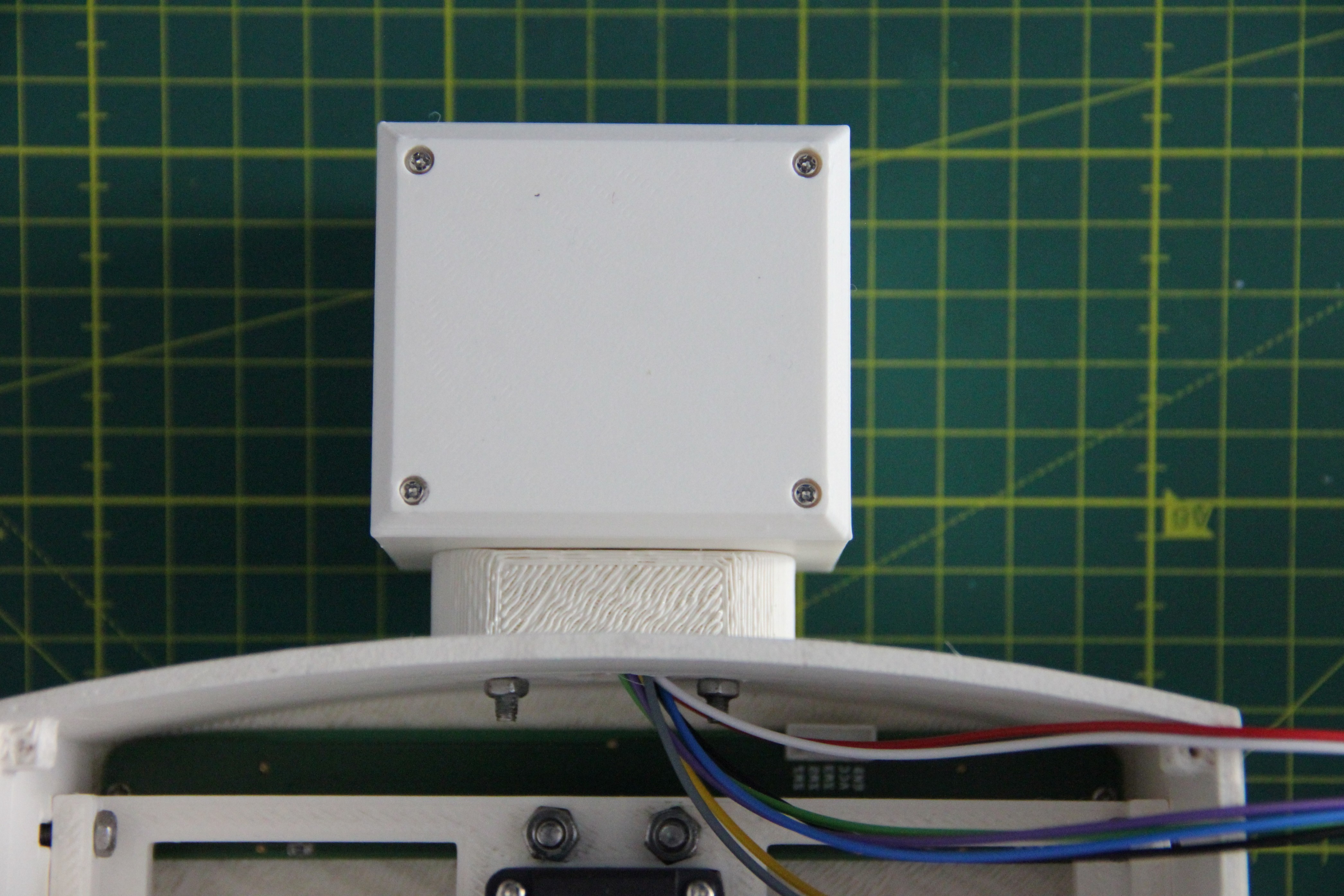
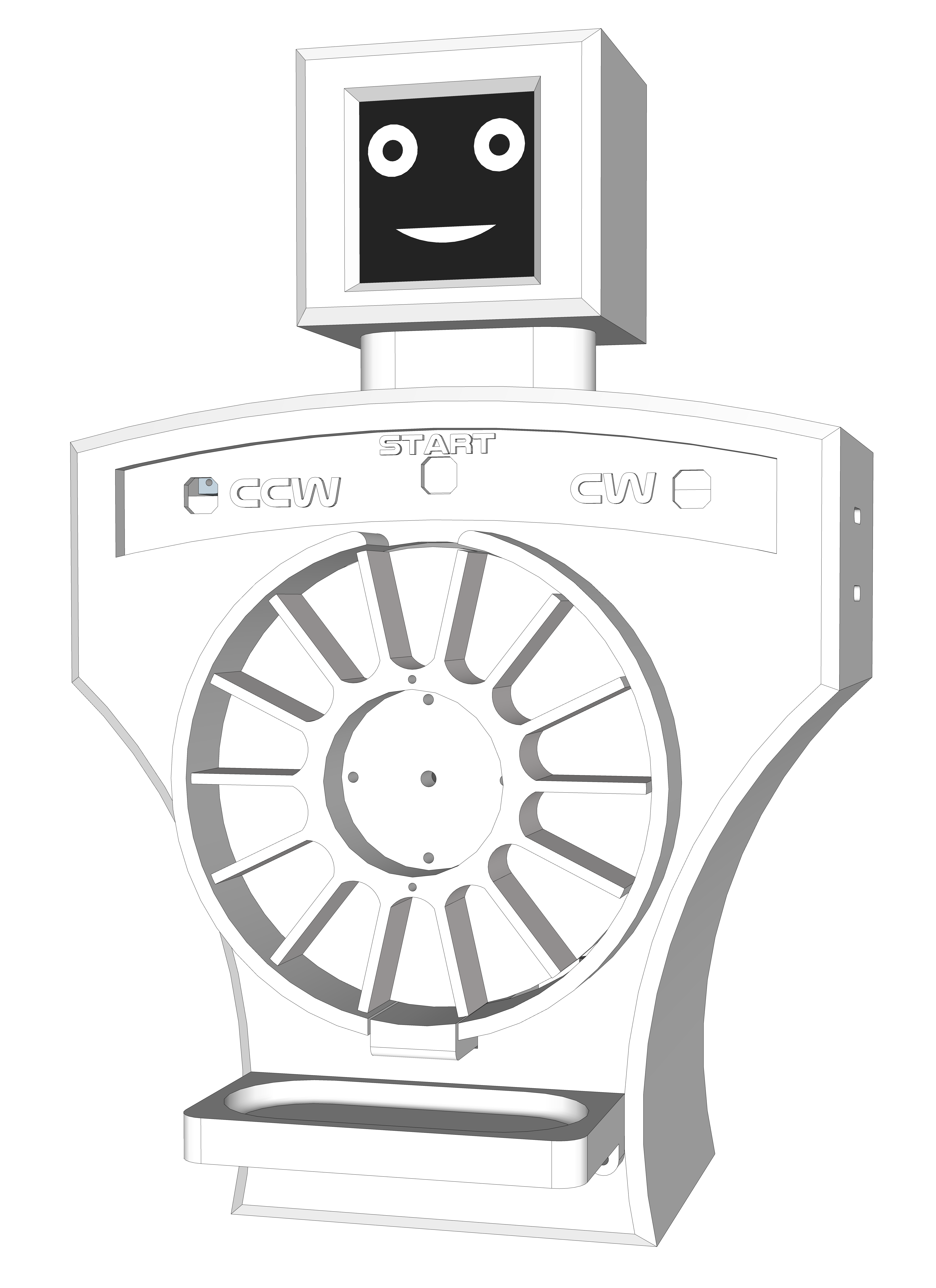
The robot has exactly the 80s look I wanted.
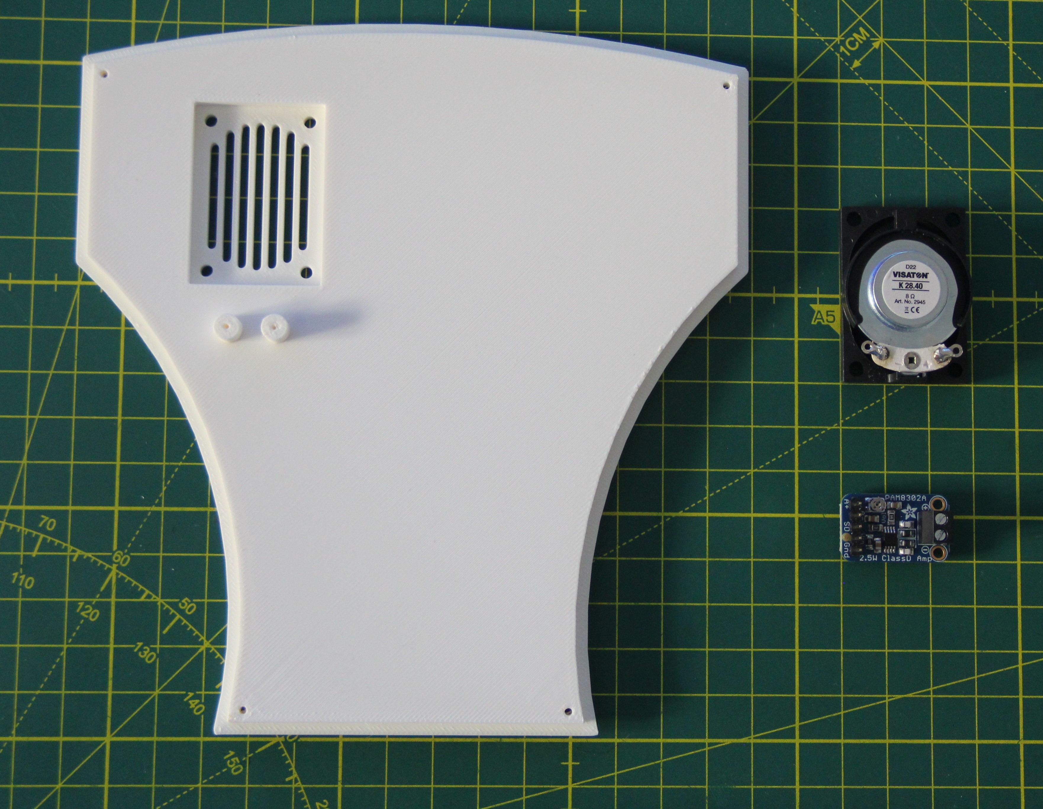
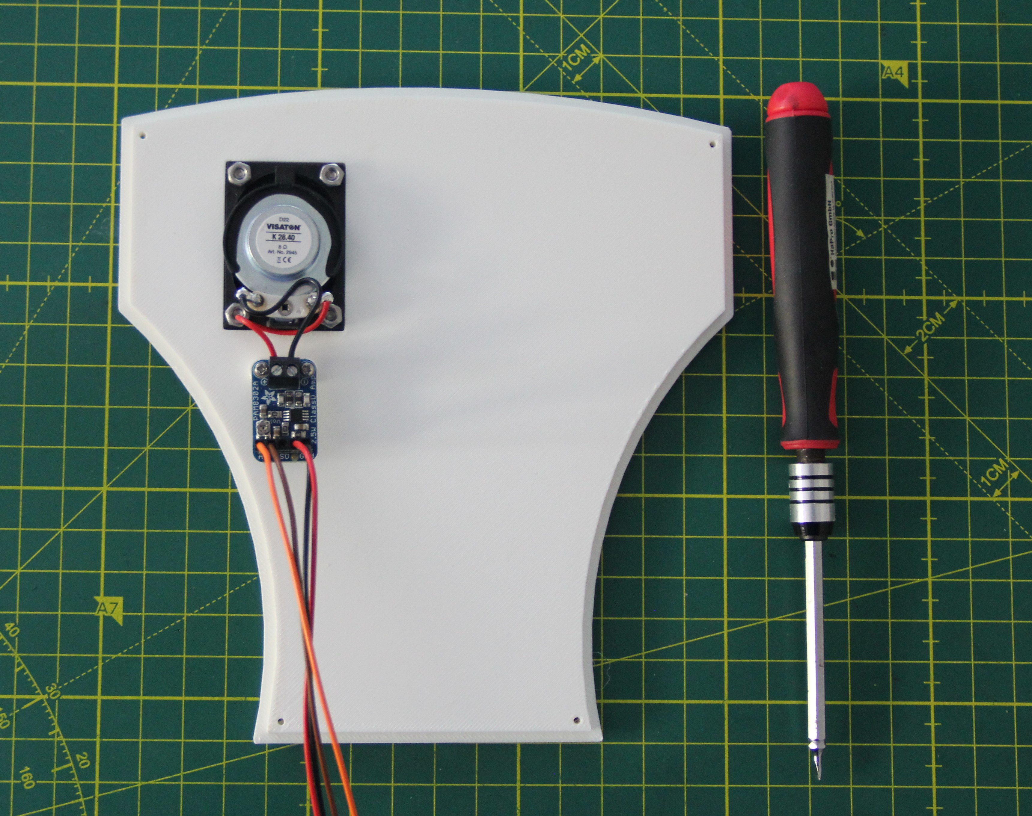
Next, the back panel, the VISATON K28.40, and the Adafruit PAM8302 breakout were needed. The speaker was screwed to the back panel with four M3 x 8mm stainless steel screws and nuts, and the breakout with two self-tapping stainless steel screws M1.7 x 6mm. Afterward, the speaker was wired. For the breakout, I again made a custom connector.
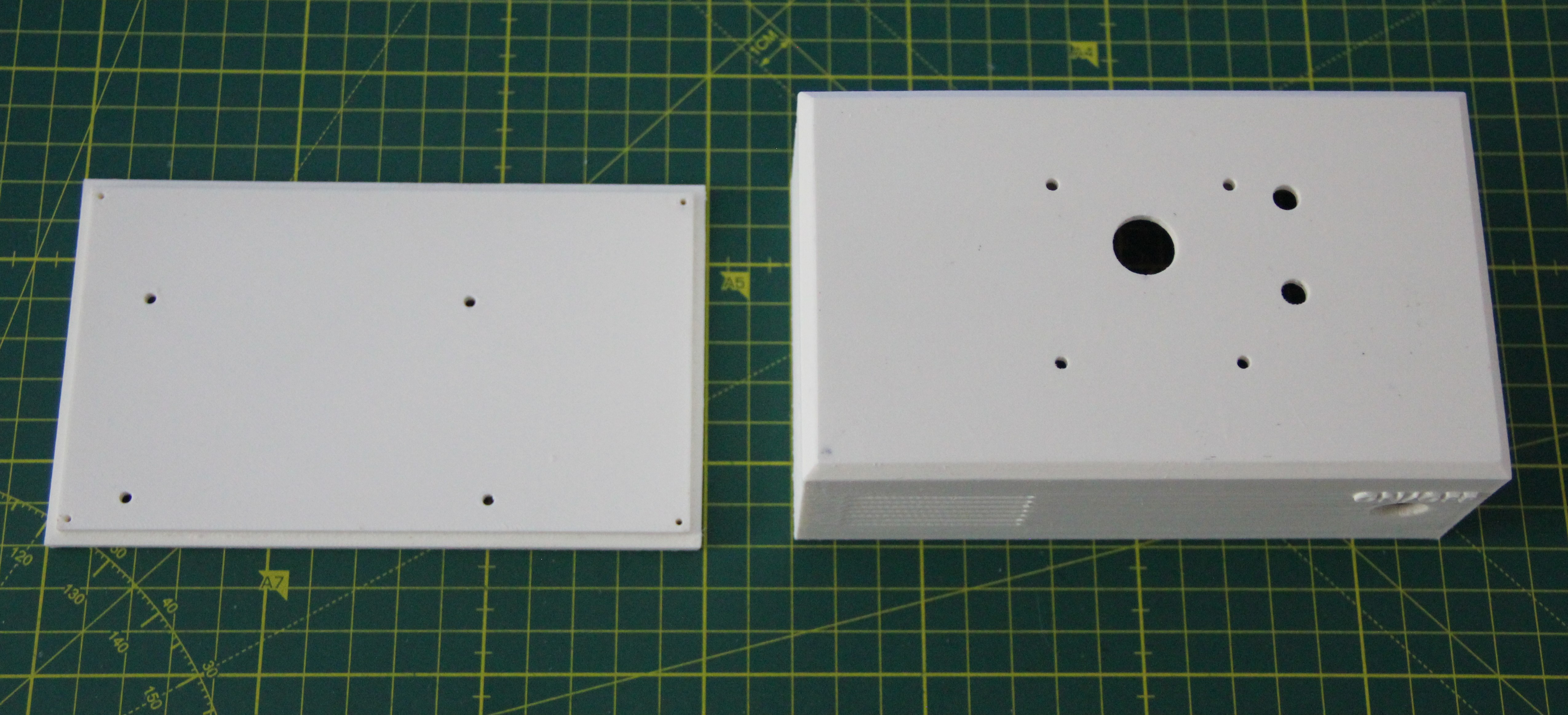
In the meantime, the last two parts needed were 3D printed.
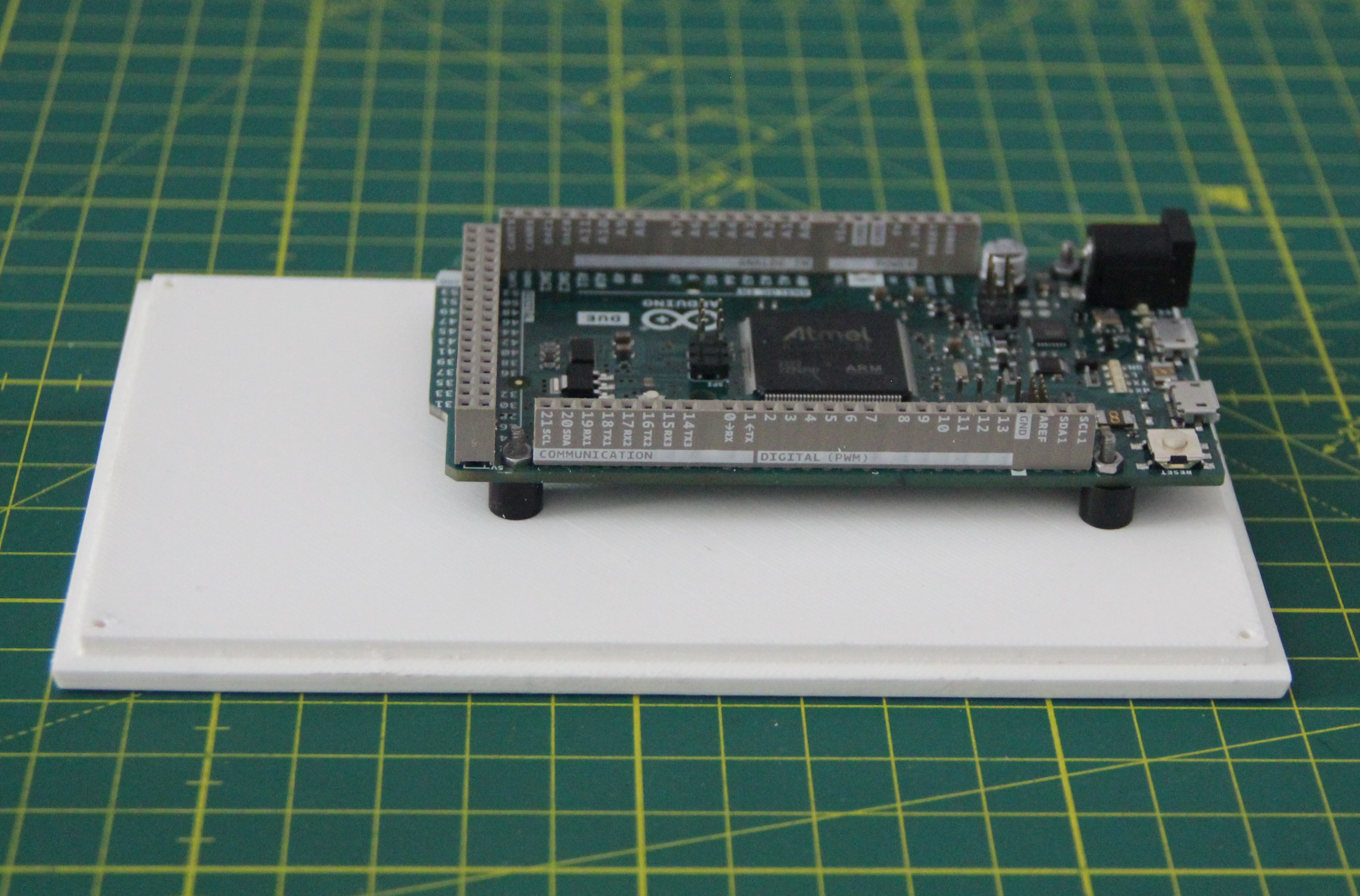
The Arduino Due was screwed to the base plate using four 6mm spacer sleeves and four M2 X 16mm stainless steel screws and nuts. The reason for not integrating the spacers into the base plate is to better align the Arduino Due so that the two USB connectors are aligned with the corresponding holes in the box.
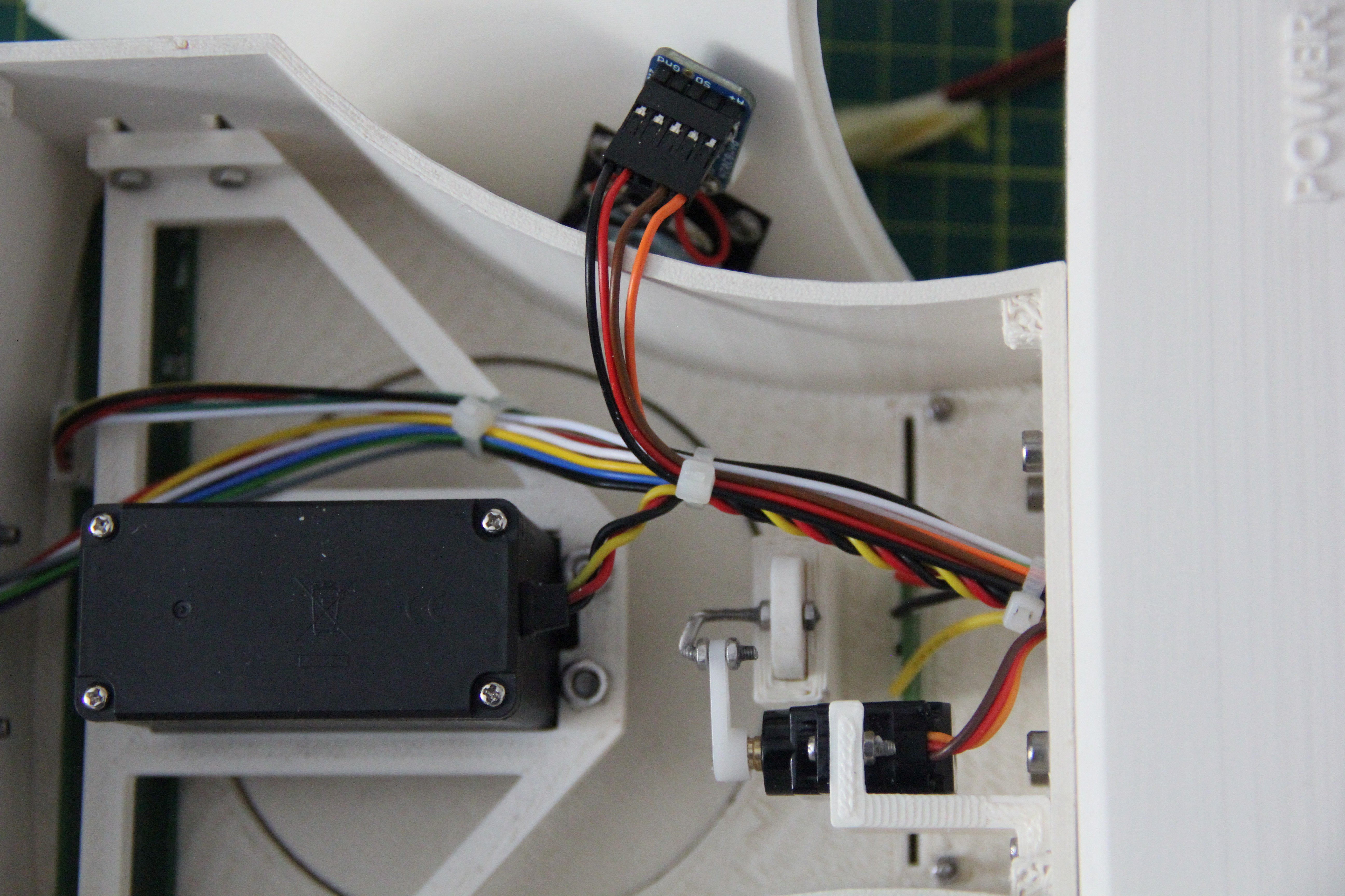
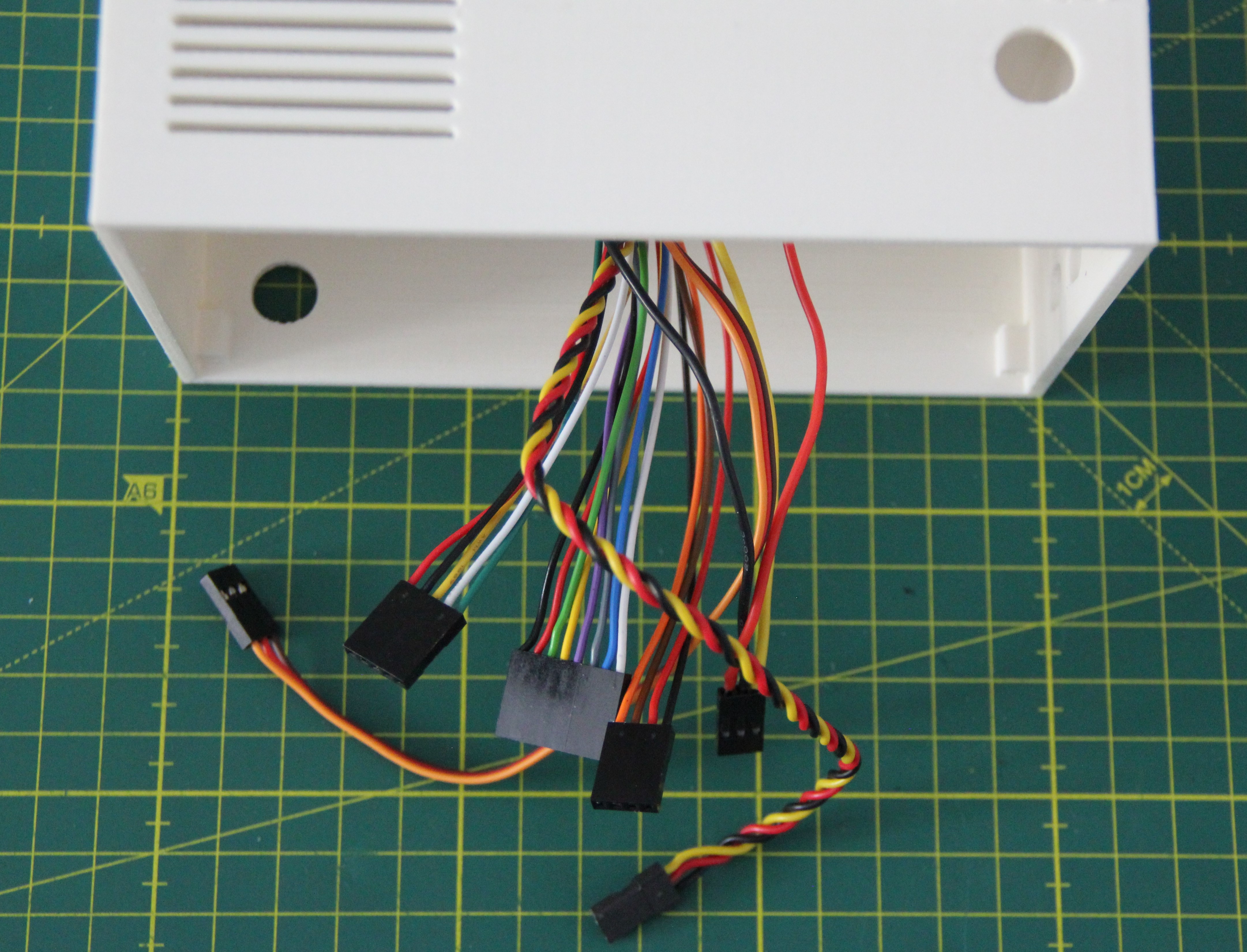
Next, all the cables were fed through the opening in the box, then the upper body of the robot was bolted to the box. Four M3 x 10 mm stainless steel screws and nuts were used for this.
The cables of the back panel were also led through the opening and the cables were tightened with cable ties so that the mini servo can move freely.
In the next step, the back panel was screwed to the upper body using four self-tapping M1.7 x 8mm stainless steel screws.
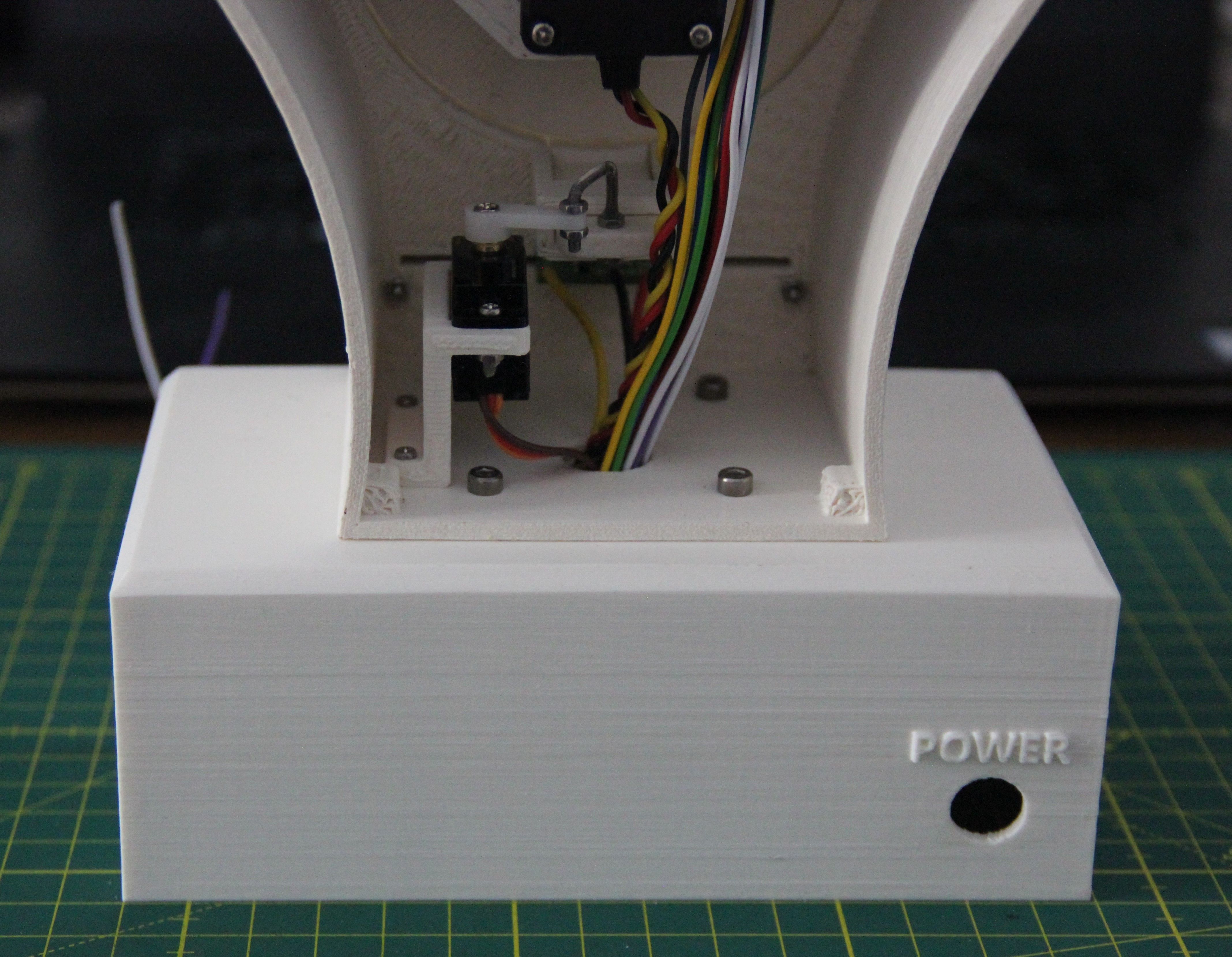
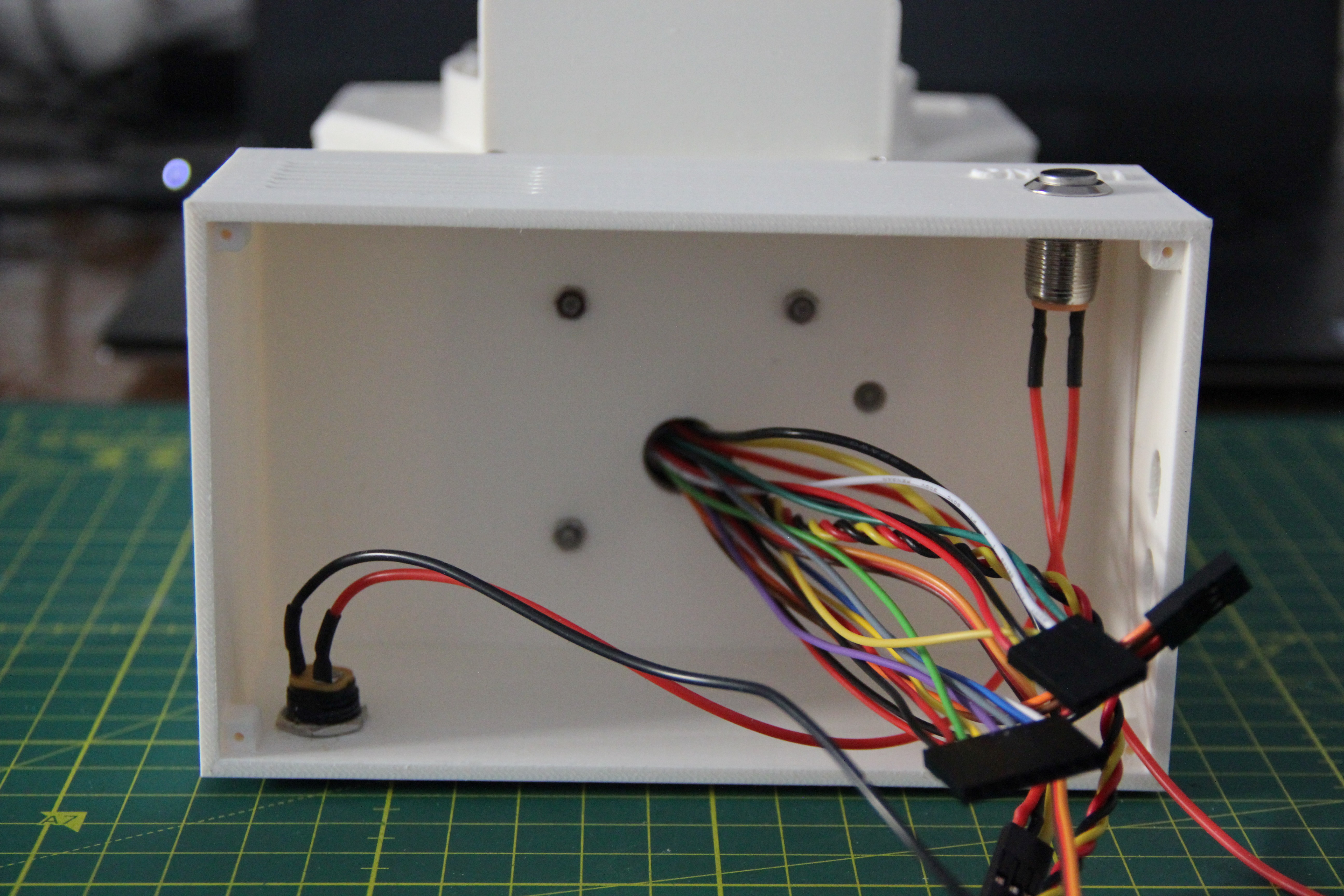
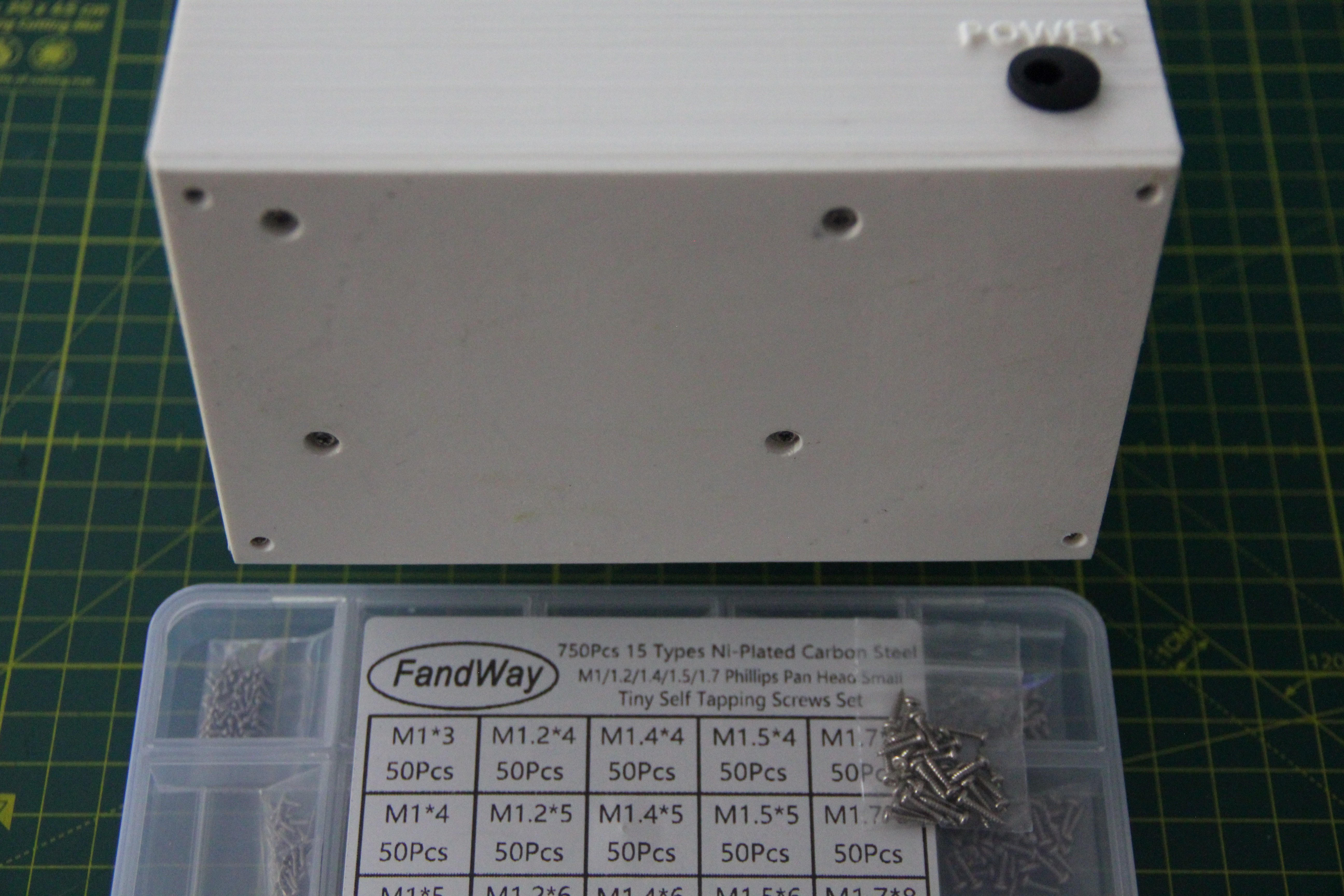
The two remaining holes in the box are for the 5.5mm x 2.1mm power jack and the on/off switch, a latching push button in stainless steel.
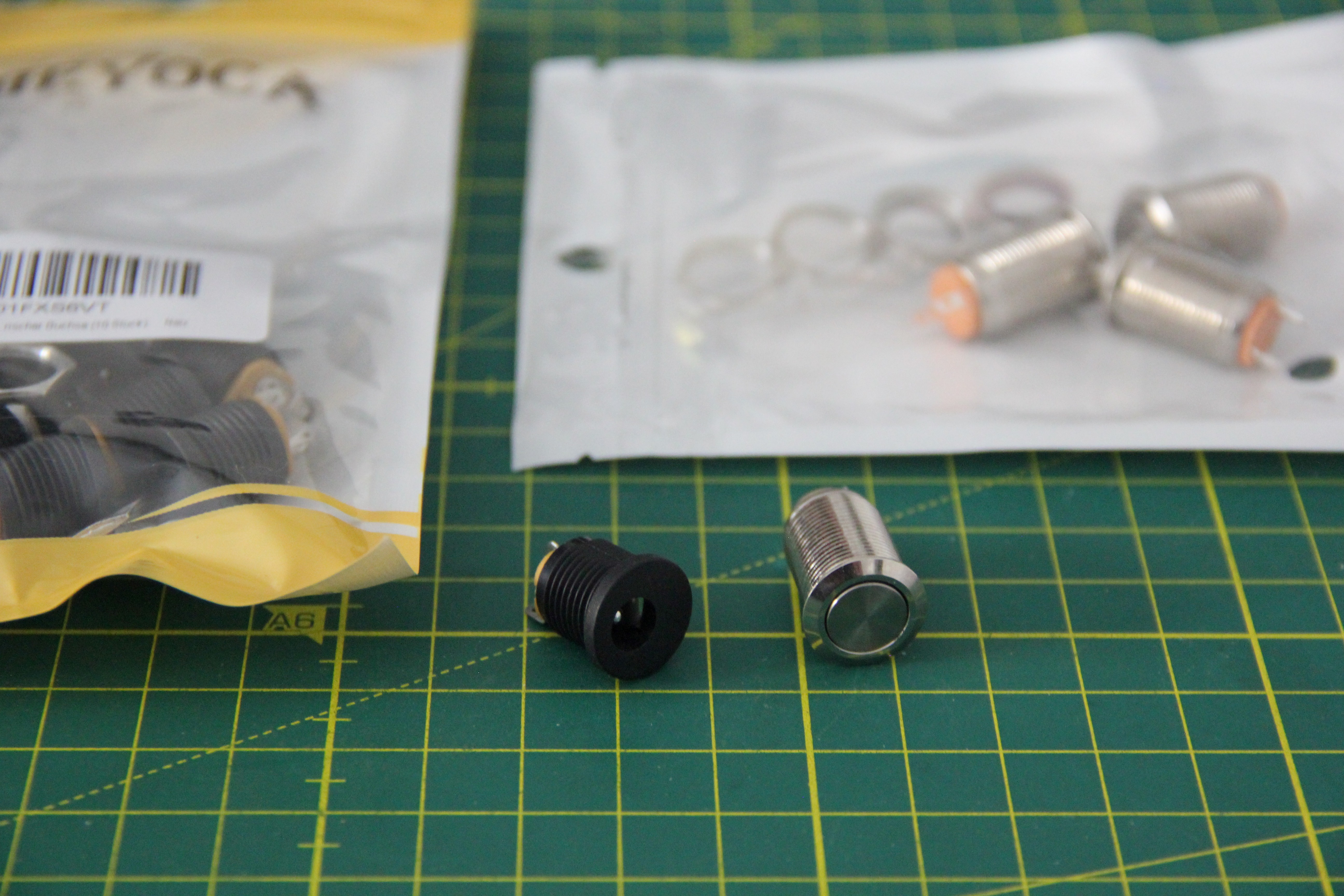
All cables were shortened accordingly and fitted with connectors.
Then the power jack and the on/off switch were mounted and wired.
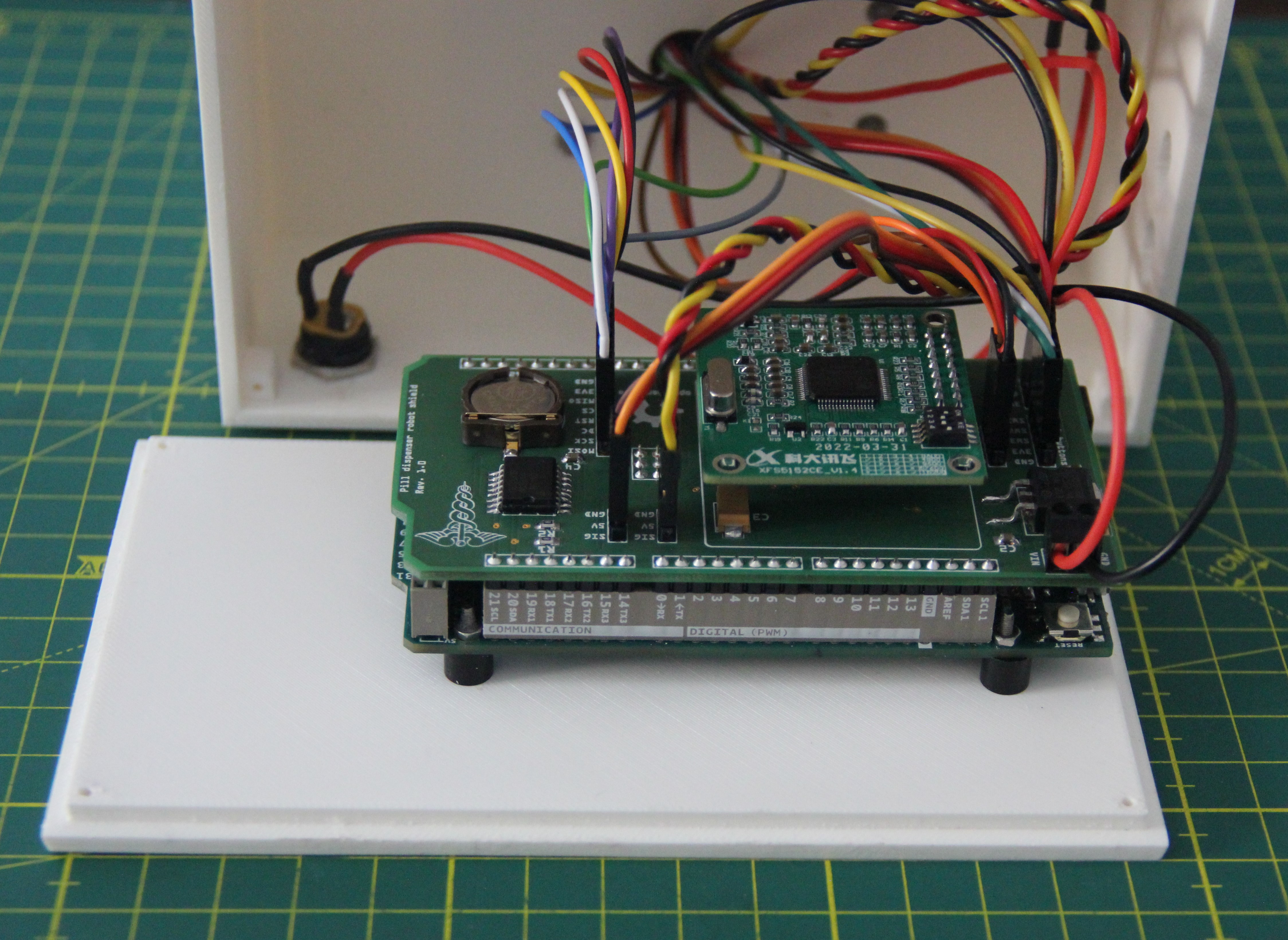
On the Arduino Due mounted on the base plate, the shield PCB was plugged on, then the TTS module.
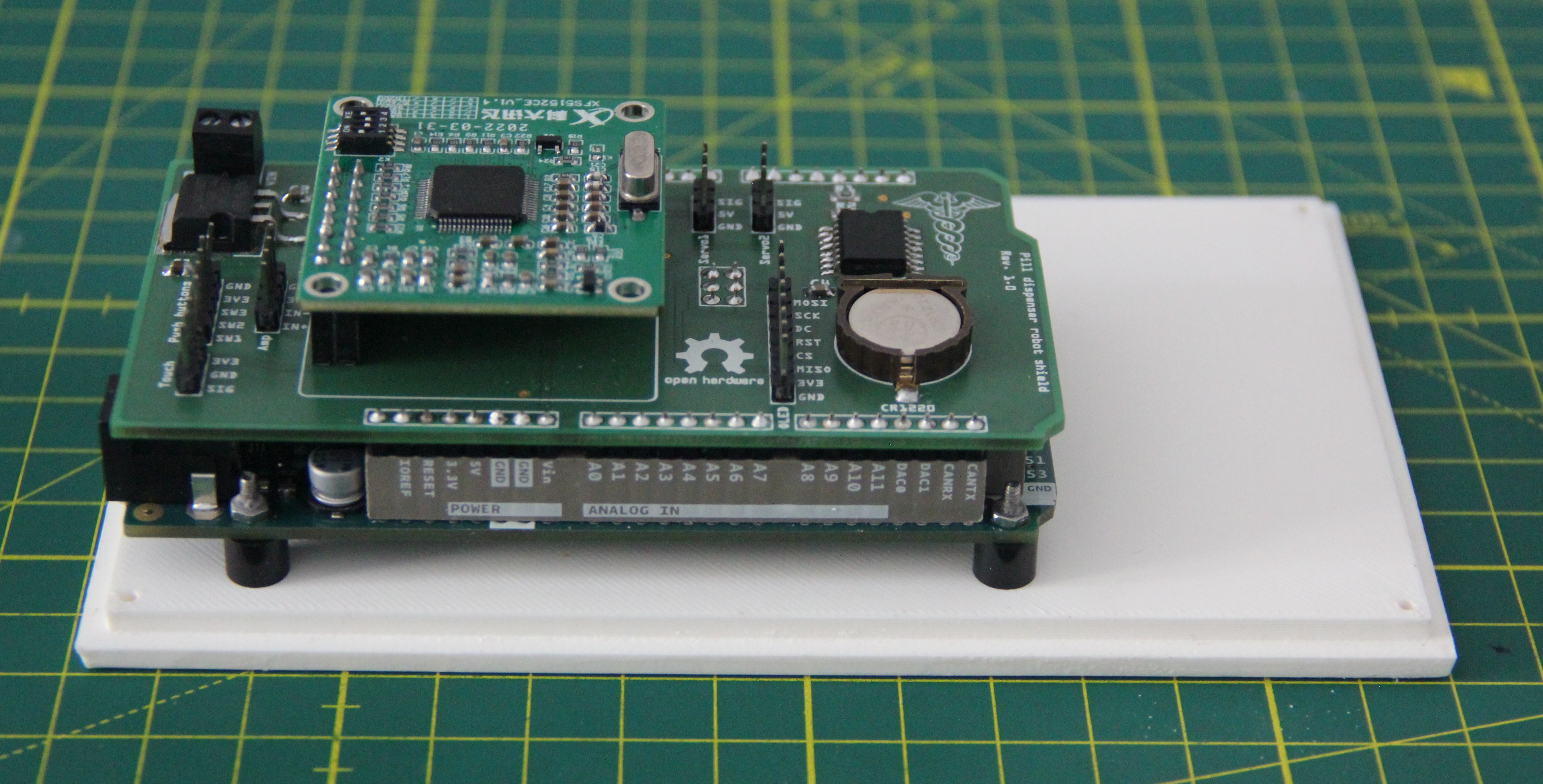
The CR1220 coin cell powers the DS3231 for about 5 years.
Next, the prepared connectors were connected to the shield, and the cables for the power supply were connected to the screw terminal.
The subsequent function test, fortunately, went smoothly, so that the base plate could be screwed to the rest of the robot using again four M1.7 x 8mm self-tapping stainless steel screws.
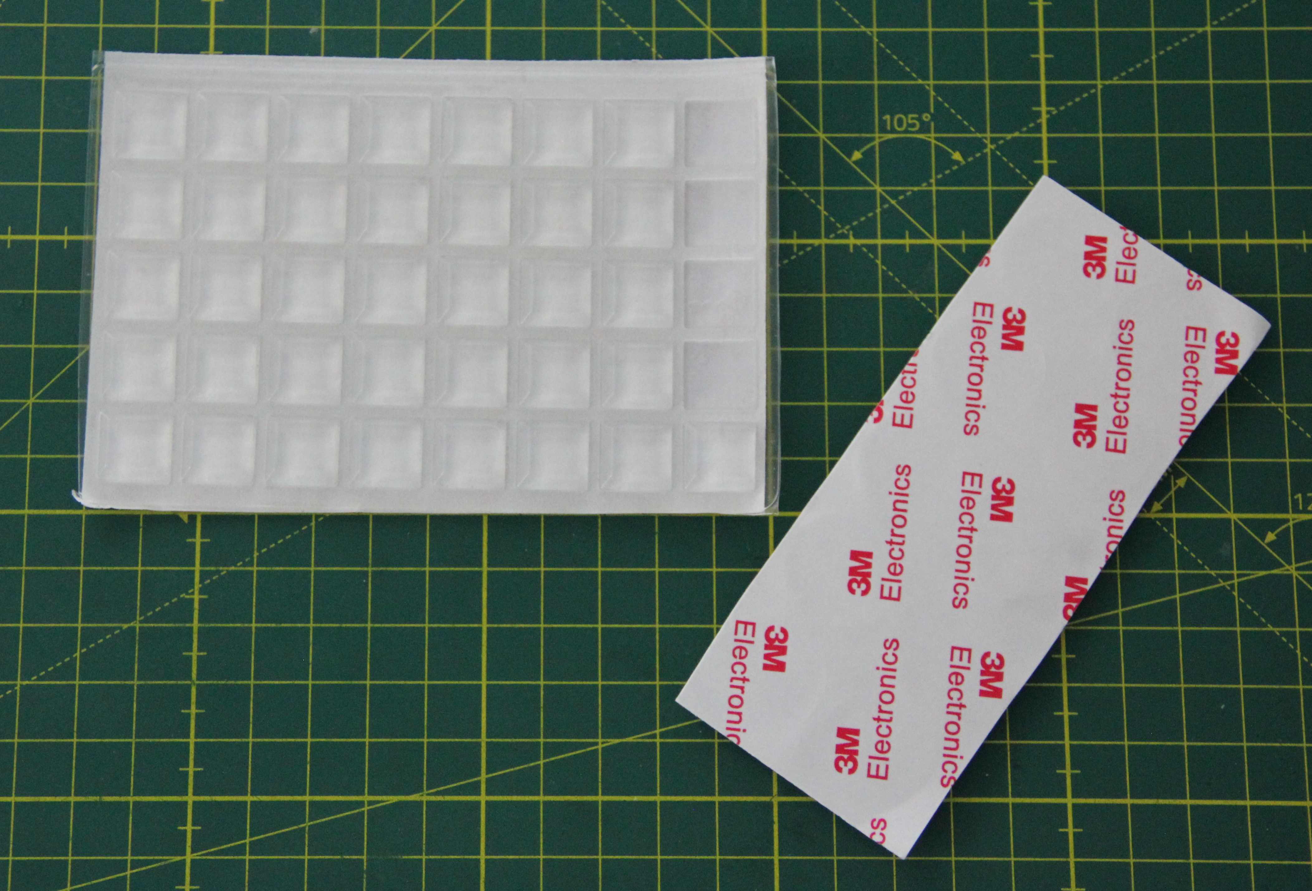
Since the base plate is very smooth, four self-adhesive silica gel pads were added.
Discussion
Number of chambers
At the moment the drum is divided into 14 chambers. At least two 300mg pills fit into each chamber. The drum has a diameter of 88mm. This gives a circumference C of:
and therefore an arc length L per chamber of:
If one wants to keep the arc length, one can calculate the diameter of the drum as a function of the number of chambers n:
With 21 chambers, for example, this would result in a drum diameter of approximately 132mm.
360° servo vs. gearmotor with absolute encoder
For the current version, I use a 360° servo for simplicity. Using servo.writeMicroseconds(us) and corrections you get the required resolution for 14 chambers. But with 21 chambers the resolution of the servo is not sufficient anymore and you need a gear motor with an absolute encoder and a corresponding motor driver.
Touch sensor vs. fingerprint sensor
For example, if you have small children in the household, it may be necessary for the robot not to dispense the medication automatically. You could use the touch sensor or the three push buttons to enter a password. A more elegant solution would be a fingerprint sensor like the Ultra-Slim Round Fingerprint Sensor or Optical Fingerprint Sensor from Adafruit. Since up to 80 respectively 162 fingerprints can be stored in the onboard FLASH memory of the sensor, one could also store the fingerprint of a second person (such as a mobile caregiver or a nurse) in case the patient is indisposed.
Uninterruptible power supply
Currently, I use a 12V wall wart to power the robot. However, if a failure to take medicine leads to life-threatening situations, an uninterruptible power supply (UPS) is recommended, which provides emergency power to the robot when the main power fails. There are quite a few 12V mini UPSs on the market, so it's not worth the trouble to integrate it into the robot.
Commercial products
There are a number of comparable commercial products on the market. They all have one thing in common: they are very expensive, I cannot afford them, and my health insurance does not cover the costs either.
- Pria: Your personal home health robot
- Hero's smart dispenser
- MedaCube pill dispenser
- Philips medication dispenser
- Livi: Smart medication dispenser

This work is licensed under a Creative Commons Attribution-NonCommercial 4.0 International License.