Close
0%
0%

DIY Home Rover

Like a commercial/OTS robo floor/vacuum cleaner, but totally built as a DIY project and bringing in customizability

Similar projects worth following
This project aims to DIY-recreate what one would usually buy off-the-shelf as a robot vacuum cleaner like the Roomba available from iRobot, or what other companies have recreated it as. Such devices had become increasingly popular during the pandemic to help with household chores but are usually not open designs and are usually opaque in terms of the data they might be sharing.

By building it as a open source design in a kit format (with sufficient variability subject to local conditions) with the code and platform readily and openly available, it can provide a useful introduction to robotics for anyone interested in learning, plus when completely made, the hope is that it becomes a device of household utility rather than a vanity item.

I have a couple of reasons for creating this: (i) Doubting the efficacy of existing solutions in the market (even though I have come across products with good reviews, while most have bad reviews), (ii) Having control over the stack of what I build (spare parts) and the generated data, and of course, the most important, (iii) the educational aspect of building this - as it will not just teach fundamentals of robotics to whoever builds it, but also some degree of autonomous location mapping and provide a platform to try more experiments in the future if needed.

This project also marks my return after a pretty long hiatus from the Hackaday community.

Premise

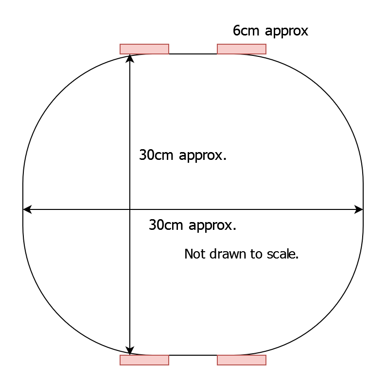
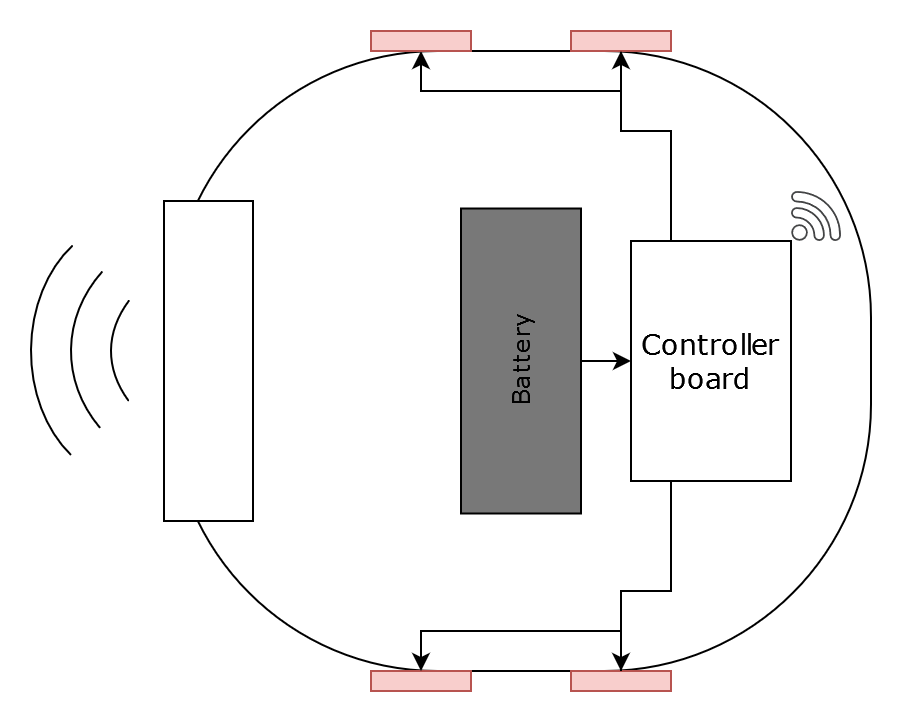
During the pandemic and afterwards, a lot of robot vacuum cleaners proliferated in the Indian market at least (and I would guess in other markets as well) - exhibit 1, exhibit 2, exhibit 3. These are small battery-powered 2-wheel robots, containing sensors, and a small vacuum cleaner and a few rotating brushes that aim to get rid of the floor dust in an autonomous fashion. While they all lie somewhere in the 200-300 USD price range, I have always wondered how effective they are in reality - plus these devices do not have readily available spare parts available in case things go wrong, their firmware and electronics is closed and so is the app bundled with them.

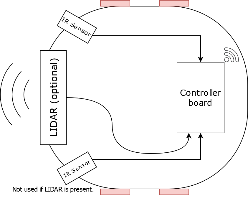
I have always wanted to build something like this for myself so that I can learn the basic premises behind this like SLAM, plus local inference if running computer vision algorithms. Also there is a DIY element to this whole thing wherein you can pick and choose what works best for you, while this project will provide a standardised hardware option, builders of this project can choose to, if they wish, bring SBCs that they already have while not being too much of a porting hassle.

The downside of a DIY approach is unfortunately that this project may not appeal to someone who is looking for a ready-made solution or not ready to invest the time and effort necessary to build this and customize it to their availability based on the components that one can source locally. But the educational aspect of this project is the reward.

  • 1 × Base frame 30cm dia. circle wooden/acrylic frame. Wooden frame may be used if SLA battery is used because of weight.
  • 4 × Geared DC motors Approximately 100 rpm, high torque
  • 1 × 12V battery Can be a SLA / LiPo battery based on availability
  • 1 × BeagleBone Blue Used because of its integrated motor drivers and sensors. Will also suggest alternatives in project design
  • 1 × Connecting Wires / Connectors When the BeagleBone is used, JST connectors will be needed to connect the motors.

  • Discussing the software stack

    Kumar, Abhishek04/25/2023 at 13:55 0 comments

    For the software, I intend to stick to ROS (Robotics Operating System), which provides a stable software base for the robot to build on top on.

    To be elaborated with more details as the design progresses.

  • Discussing Component Choices

    Kumar, Abhishek04/25/2023 at 13:54 0 comments

    This log is about discussing the component choices and tradeoffs.

    Frame and Drive

    Overall TL;DR is that this is a differentially-driven 4-wheel robot (2 left motors and 2 right motors) because adding two more motors will make the frame stable without adding a castor wheel.

    The red rectangles in the top view are the wheels here.

    Base frame material choice is ~2mm thick plywood as it will be strong enough to support the weight of the electronics. Laser cut options will be provided along with the DXF in due course as the design progresses. The laser cut frame may only be able to support a LiPo battery though because of weight restrictions. More below.


    Battery, control electronics

    For the battery, there are basically 2 choices - LiPo (2S/3S batteries) and SLA (12V, 7Ah) batteries. In my case, while the 12V SLA is easy to source and cheap, it has the disadvantage of being not as environment friendly because of the presence of lead, and heavier than the LiPo option. A LiPo will add additional cost both by being more expensive as well as with needing dedicated charging hardware circuitry. When being turned into a kit, while LiPo will be the preferred option, a SLA variant will be also kept for cost effectiveness.

    I personally will be using the SLA to prototype as I already have one at hand.

    For the controller, I would ideally like to split it into two parts, one board with a small microcontroller (like the Pico, or a STM32) that is in control of all the sensors and motors, getting data and doing minimal processing and then a more powerful SBC like a BeagleBoard or a Raspberry Pi (I have both, and will provide options for flexibility here). The more powerful SBC will control the MCU board, which will in turn, control the hardware.

    The aim of DIY-ness here is to offer the choice to use the hardware people building this may already have lying around. Let's say somebody has a RPi, they can use it. Somebody has a spare BeagleBoard, they can put it into the build. Some of the more obscure Allwinner boards may have a bit of difficulty with respect to GPIO but as long as there's a reasonably high speed UART/USB interface available, we should be fine.

    What I would be using to prototype the design is a BeagleBone Blue. BeagleBoard has been gracious enough to provide me with their boards from time to time since I was a student who worked to develop BeagleLogic a fairly long time back, and the key feature of this board is that while it's a normal SBC, it has a lot of control electronics integrated within for robotics applications. Including but not limited to - integrated WiFi and Bluetooth, a 9-axis IMU, 4 motor drivers, servo support, quadrature encoders and more.

    I do hope to design a more affordable standalone controller using the Pico in due course as an option which can directly plug in to any SBC via USB, and has to be supplemented with whatever SBC the user decides to bring.

    Sensors

    Depending upon the computing device the user wants to use, this can vary from low complexity (IR sensors) but low autonomy, to LIDAR sensors (high autonomy, but more computational power). Vision sensors can be incorporated as well as long as on-device processing is done and no information is uploaded to the cloud.

    Connectivity

    The ideal way of connectivity is that this device will aim to connect to the local WiFi network and/or Bluetooth and be controllable by devices within the local bounds of the house without sending anything out. If the user is technically proficient to configure the device to be remote controllable by means of a VPN/proxy, it is their responsibility to configure their home network appropriately but by default nothing will be sent out.

View all 2 project logs

  • 1
    Base Frame Assembly

    Assemble all the components onto the frame on their designated locations. This includes the battery, the control electronics (BeagleBone Blue/other controller), the sensors (IR / LiDAR), camera (if installed).

  • 2
    Wiring

    Connect the motors and sensors to the controller board as per the block diagram. A detailed plan will be provided as the project develops.

  • 3
    Boot the board (in development mode)

    Switch on the board, let it boot with the prebuilt image, connect to it via a hotspot (and then connect it to the local network for development if necessary), and then proceed to load the software. A more productionized system will make most of this automatic, but in the initial stages, some amount of DIY is needed.

View all 4 instructions

Enjoy this project?

Share

Discussions

Similar Projects

Does this project spark your interest?

Become a member to follow this project and never miss any updates