 Neil Lambeth
Now it's time to get programming. When introducing young students to programming, you'd normally start by blinking an LED, so let's do that but we'll do it controlled over the internet by an app on your phone. Then we'll make the app control your robot!
To do this we'll use blynk.io
Blynk is a low code Internet of Things framework. It works very well with the ESP32 and Arduino. There's a free plan with enough features to create our app for controlling a robot.
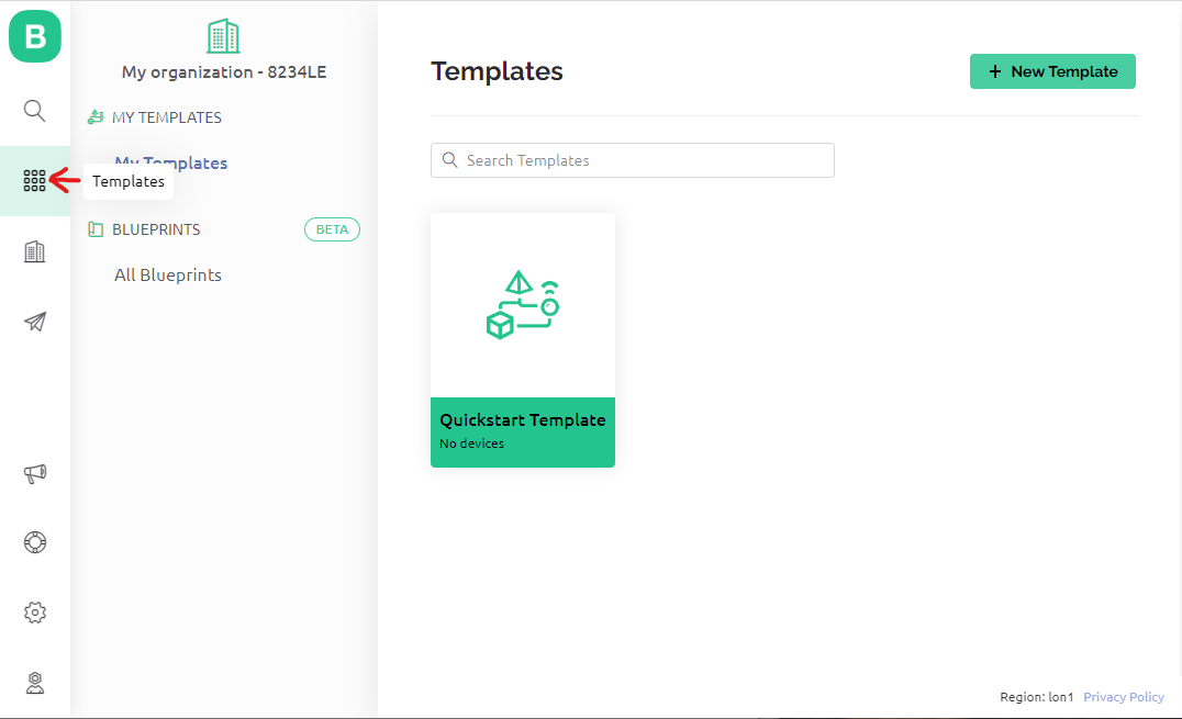
Blynk has got some great examples to get you going, we'll use one of those but we'll modify it for our needs. After you have created a free account, go to you dashboard then click on Templates on the left hand side, then click on + New Template.
Give your new template a name, I called mine 'Robot Controller'. The hardware should be ESP32 and the connection should be WiFi.
Click on Datastreams, then + New Datastream.
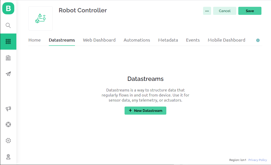
Select Virtual Pin, then click on Create.
Repeate this 6 more times, your datastreams should look like this:
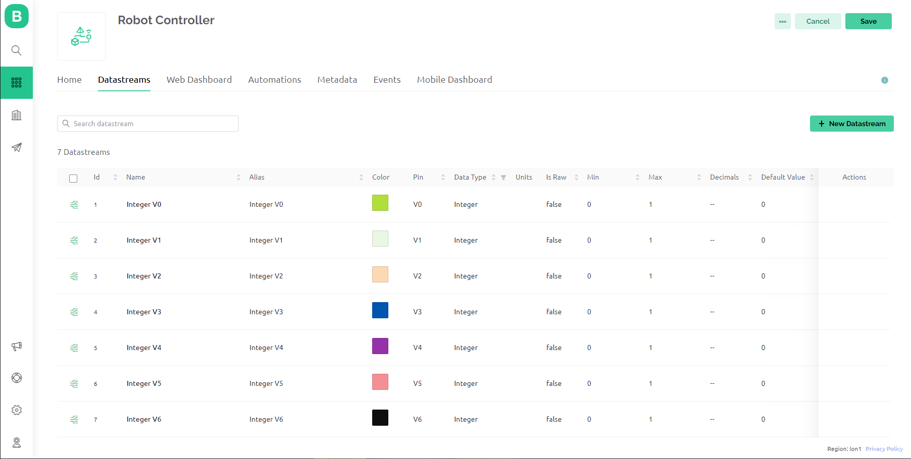
Click on save in the top right corner.
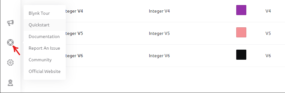
Click on the lifebuoy icon in the bottom left of the screen, then select Quickstart.
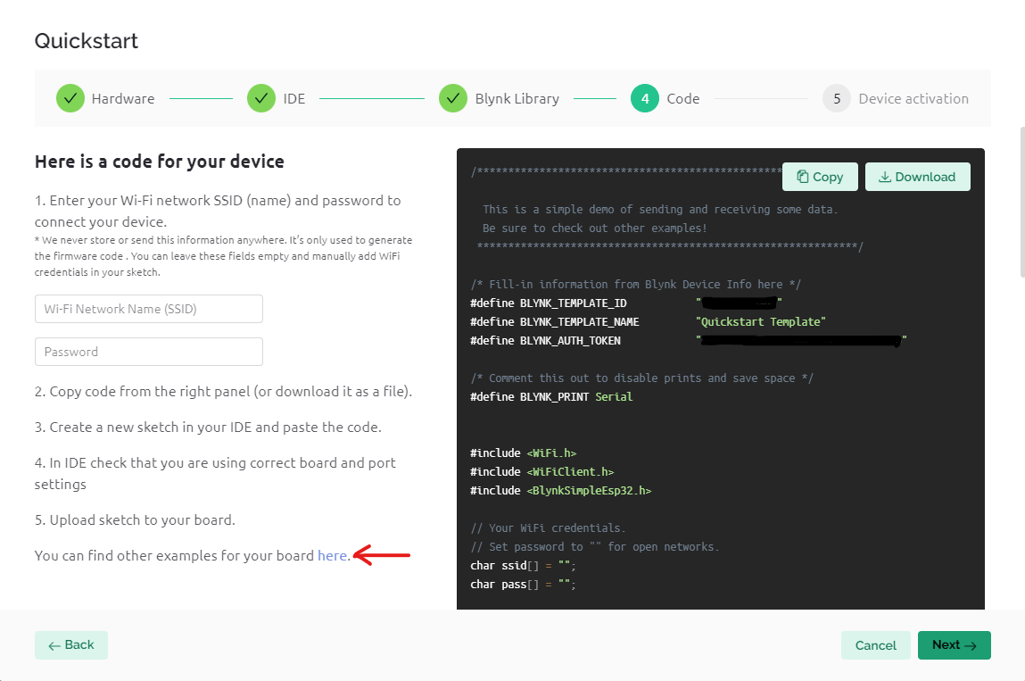
Click on Let's Go! Then select ESP32 as your hardware. Follow the instructions to install the Blynk library for Arduino.
You'll be presented with some example code, but we are going to use a different example.
Click on the other examples at the bottom of the screen.
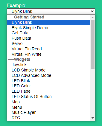
Select the Blynk Blink example from the drop down box on the Left.
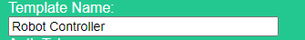
Also change the Template Name to match what you called the template you created earlier.
Now click on Copy Example on the right hand side of the screen.
Open the Arduino IDE and paste in the copied sketch.
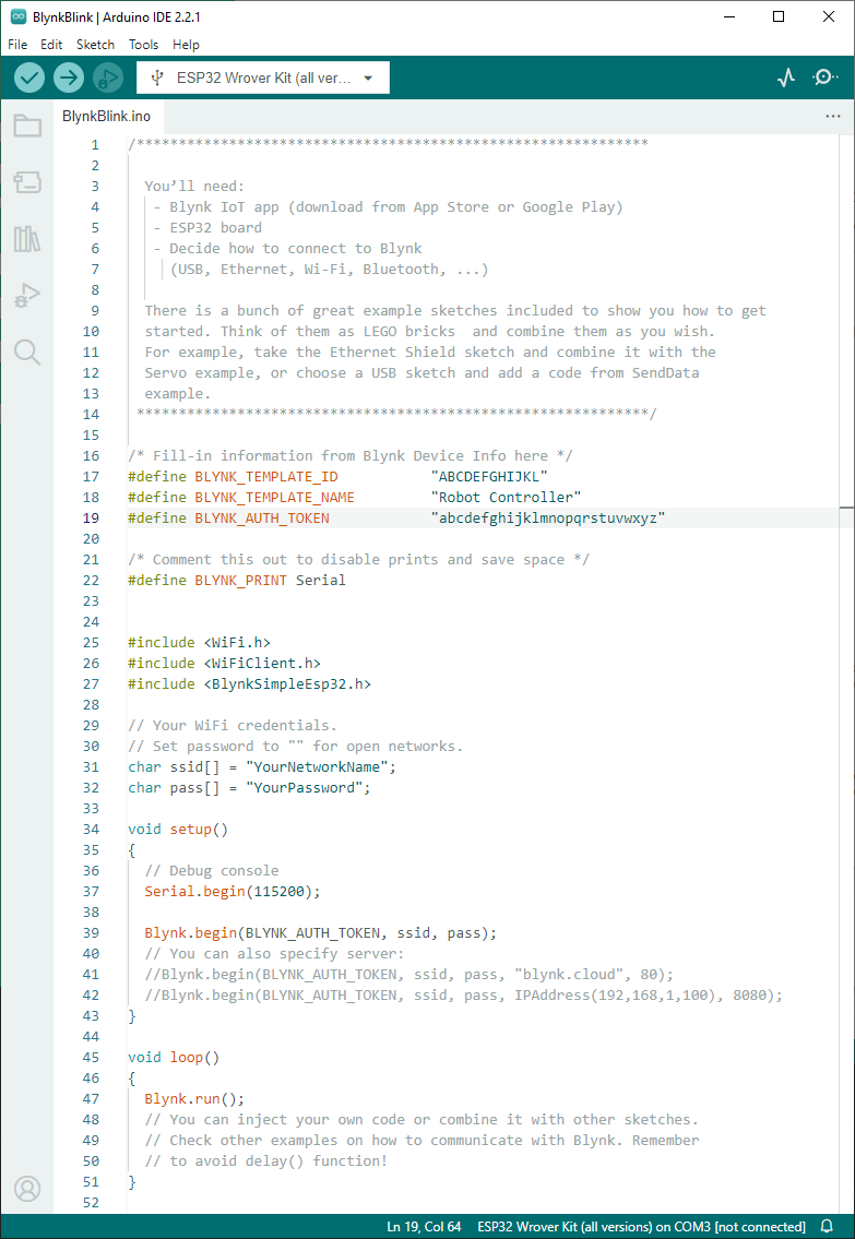
Change the WiFi credentials to match your own network.
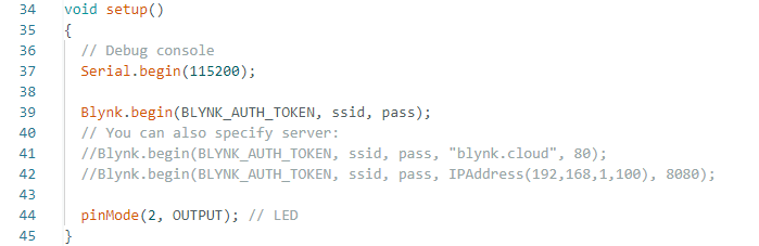
We'll now add the code to flash an LED. At the bottom of the void setup() section of code, add the following line:
pinMode(2, OUTPUT); // LED
So it should look like this:
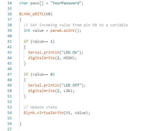
Now just after your WiFi credentials, add the following code:
BLYNK_WRITE(V0)
{
  // Set incoming value from pin V0 to a variable
  int value = param.asInt();

  if (value== 1)
  {
    Serial.println("LED On");
    digitalWrite(2, HIGH);
  }

  if (value== 0)
  {
    Serial.println("LED Off");
    digitalWrite(2, LOW);
  }

  // Update state
  Blynk.virtualWrite(V1, value);

}
It should look like this:
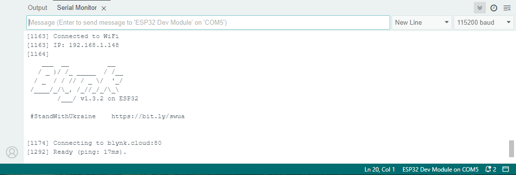
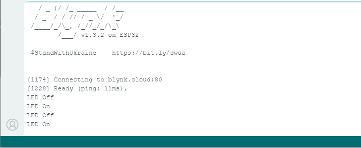
Upload the code to your ESP32 device. Turn on the Serial Monitor and change the Baud Rate to 115200. If everything is correct it should connect to your WiFI and you should see some output like this:
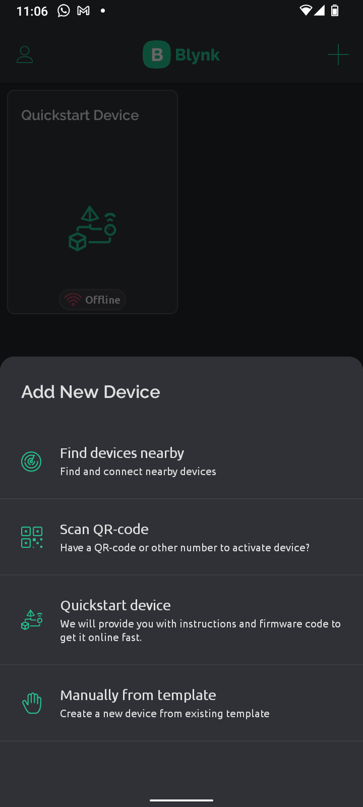
Now open the Blynk app on your phone. This has got a drag and drop interface to easily create your app. Click on the + symbol at the top right of the screen to Add a New Device. Then select Manually from template.
Select the template you created earlier, then click on Create. Now click on the spanner icon at the bottom of the screen to enter Developer Mode.
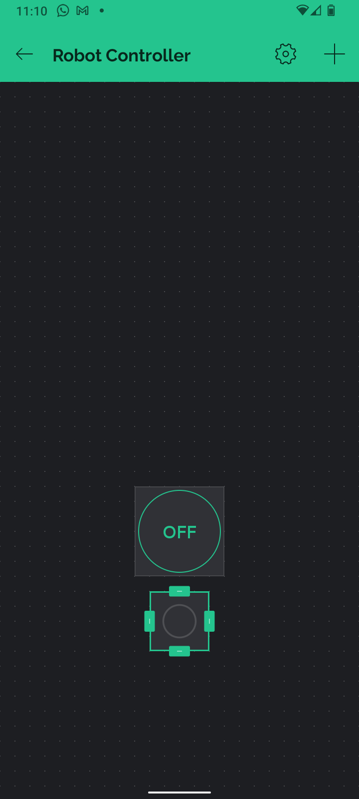
Now you can start adding buttons and other controls for your app. Click on the screen, then from the menu that appears, add a Button. Repeat the process to add an LED. Long press on the items you have just added and drag them around the screen to reposition them.
Arrange the button and LED like this:
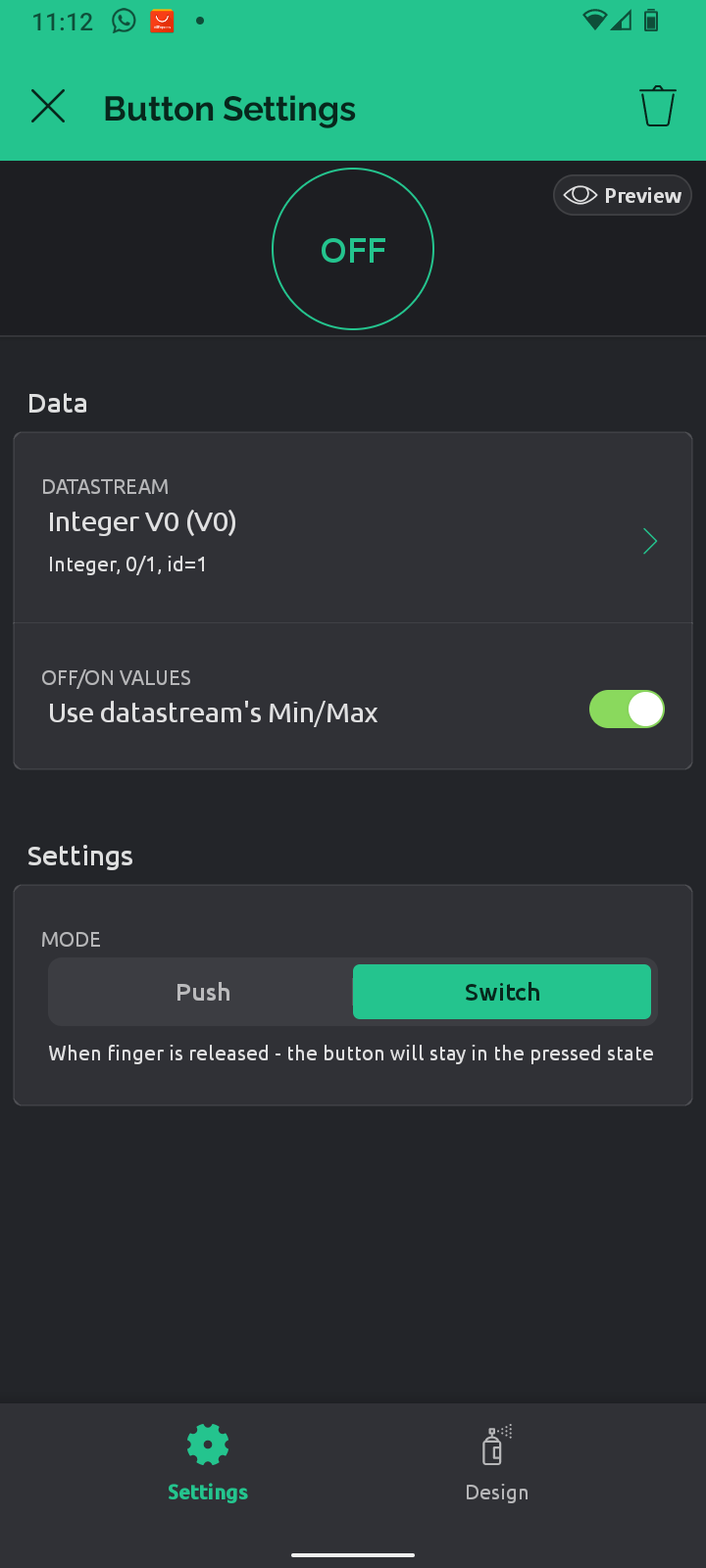
Tap on the button to change it's properties. Tap on Datastreams then select the entry at the top of the list, this should be IntegerV0.
Next change the Mode to Switch, as shown here:
Next, tap on the LED and change it's Datastream to IntegerV1. Tap the back arrow at the top of the screen to exit Developer Mode.
If everything has worked correctly, when you tap the button on the screen, the LED on the ESP32 should light up!
You should also see the output change in the Serial Monitor window.
Now we have our LED flashing, it's time to make our robot move.
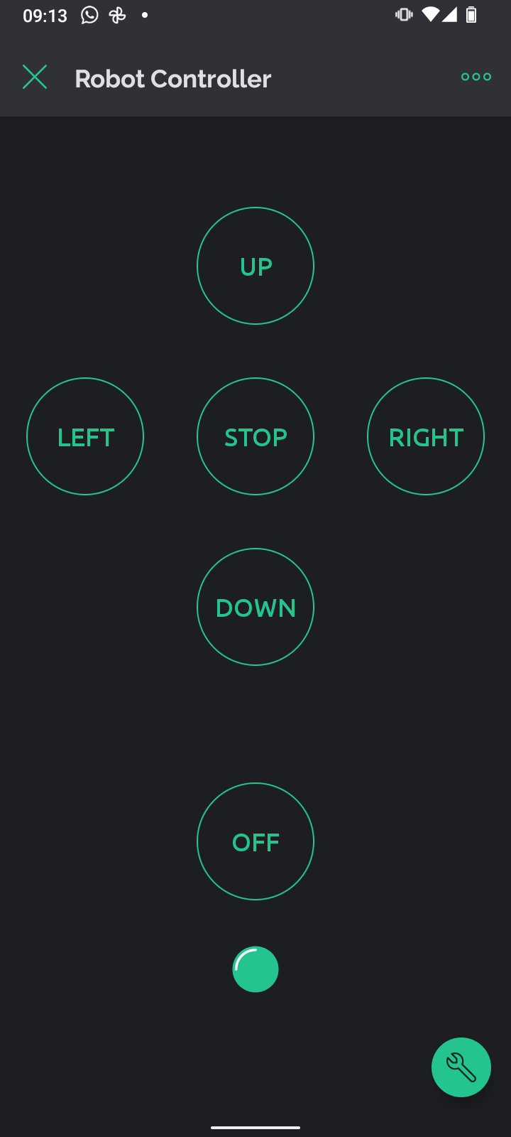
In the Blynk app on your mobile, select your Robot Controller App. Enter developer mode by tapping the spanner at the bottom of the screen. Add 5 more buttons in a cross pattern, then assign the Datastreams to the virtual pins as shown:
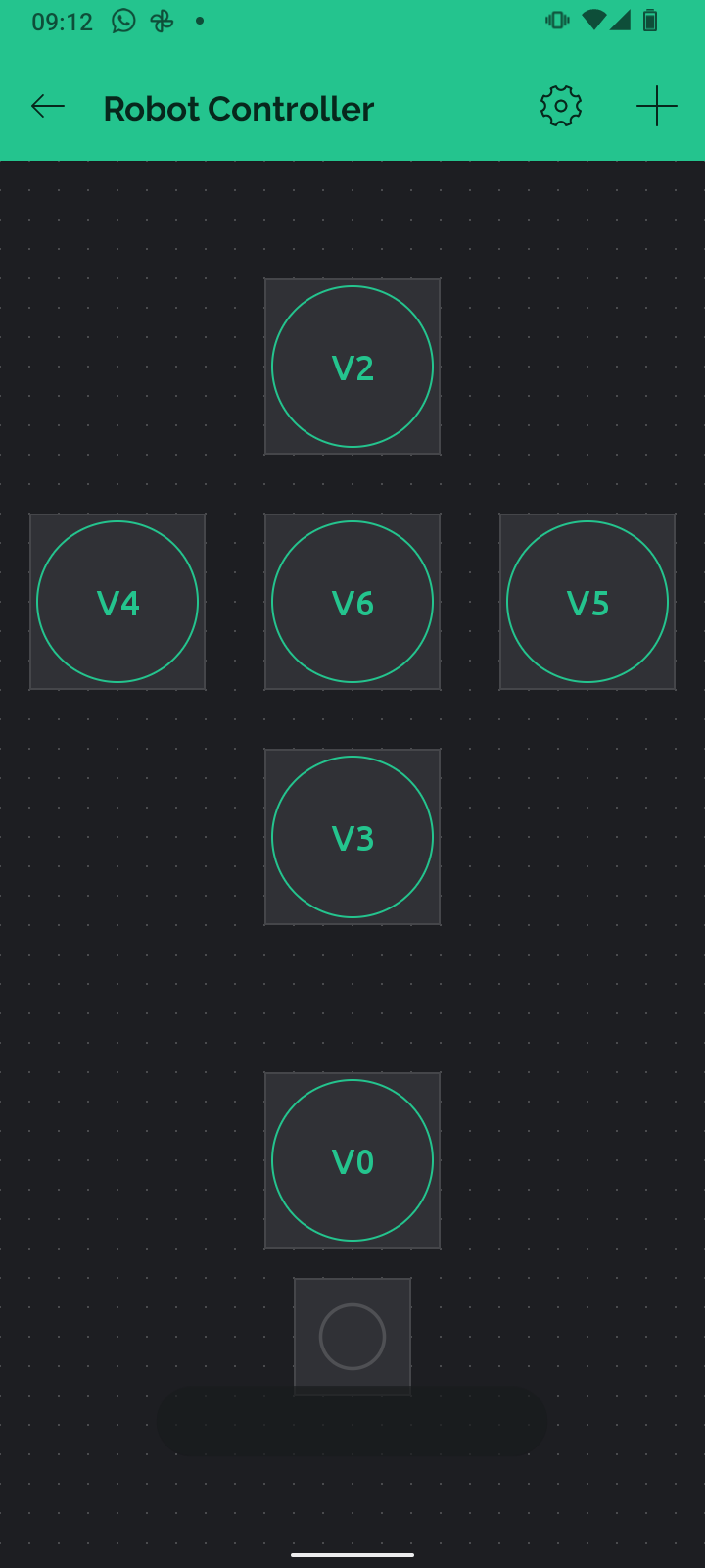
You can rename the buttons by tapping the Design tab at the bottom of the screen when you are editing the button's settings.
That's the app finished! We now need to modify our Arduino code. In the Arduino IDE, add the following code to Void setup() to create 4 output pins which will control the motors:
pinMode(18, OUTPUT); // Motor 1a
pinMode(19, OUTPUT); // Motor 1b

pinMode(25, OUTPUT); // Motor 2a
pinMode(26, OUTPUT); // Motor 2b
We now need to add some code to tell the motors which way to turn. These section of code are linked to the virtual pins we set up in the app. So to make the robot move forward, add the following code:
//Forwards
BLYNK_WRITE(V2)
{
  // Set incoming value from pin V0 to a variable
  int value = param.asInt();

  if (value== 1)
  {
    Serial.println("Forward");
    digitalWrite(18, 0);
    digitalWrite(19, 1);

    digitalWrite(25, 0);
    digitalWrite(26, 1);
  }

  if (value== 0)
  {
    Serial.println("Stop");
    digitalWrite(18, 0);
    digitalWrite(19, 0);
    digitalWrite(25, 0);
    digitalWrite(26, 0);
  }
}
This is linked to virtual pin V2, so when you press the UP button in the app, the motors rotate forwards.
We now just need to add the code for the other buttons, to make the robot go backwards and turn left and right.
Here's the full code, remember to change your WiFi credentials and add your own BLYNK_TEMPLATE_ID and BLYNK_AUTH_TOKEN.
/*************************************************************

  You’ll need:
   - Blynk IoT app (download from App Store or Google Play)
   - ESP32 board
   - Decide how to connect to Blynk
     (USB, Ethernet, Wi-Fi, Bluetooth, ...)

  There is a bunch of great example sketches included to show you how to get
  started. Think of them as LEGO bricks  and combine them as you wish.
  For example, take the Ethernet Shield sketch and combine it with the
  Servo example, or choose a USB sketch and add a code from SendData
  example.
 *************************************************************/

/* Fill-in information from Blynk Device Info here */
#define BLYNK_TEMPLATE_ID           "Your Template ID"
#define BLYNK_TEMPLATE_NAME         "Robot Control Pad"
#define BLYNK_AUTH_TOKEN            "Your Auth Token"

/* Comment this out to disable prints and save space */
#define BLYNK_PRINT Serial


#include <WiFi.h>
#include <WiFiClient.h>
#include <BlynkSimpleEsp32.h>

// Your WiFi credentials.
// Set password to "" for open networks.
char ssid[] = "Your SSID";
char pass[] = "YourPassword";

BLYNK_WRITE(V0)
{
  // Set incoming value from pin V0 to a variable
  int value = param.asInt();

  if (value== 1)
  {
    Serial.println("LED On");
    digitalWrite(2, HIGH);
  }

  if (value== 0)
  {
    Serial.println("LED Off");
    digitalWrite(2, LOW);
  }

  // Update state
  Blynk.virtualWrite(V1, value);

}

//Forwards
BLYNK_WRITE(V2)
{
  // Set incoming value from pin V0 to a variable
  int value = param.asInt();

  if (value== 1)
  {
    Serial.println("Forwards");
    digitalWrite(18, 0);
    digitalWrite(19, 1);
    digitalWrite(25, 0);
    digitalWrite(26, 1);
  }

  if (value== 0)
  {
    Serial.println("Stop");
    digitalWrite(18, 0);
    digitalWrite(19, 0);
    digitalWrite(25, 0);
    digitalWrite(26, 0);
  }
}


//Backwards
BLYNK_WRITE(V3)
{
  // Set incoming value from pin V0 to a variable
  int value = param.asInt();

  if (value== 1)
  {
    Serial.println("Backwards");
    digitalWrite(18, 1);
    digitalWrite(19, 0);
    digitalWrite(25, 1);
    digitalWrite(26, 0);
  }

  if (value== 0)
  {
    Serial.println("Stop");
    digitalWrite(18, 0);
    digitalWrite(19, 0);
    digitalWrite(25, 0);
    digitalWrite(26, 0);
  }
}


//Left
BLYNK_WRITE(V4)
{
  // Set incoming value from pin V0 to a variable
  int value = param.asInt();

  if (value== 1)
  {
    Serial.println("Left");
    digitalWrite(18, 1);
    digitalWrite(19, 0);
    digitalWrite(25, 0);
    digitalWrite(26, 1);
  }

  if (value== 0)
  {
    Serial.println("Stop");
    digitalWrite(18, 0);
    digitalWrite(19, 0);
    digitalWrite(25, 0);
    digitalWrite(26, 0);
  }
}


//Right
BLYNK_WRITE(V5)
{
  // Set incoming value from pin V0 to a variable
  int value = param.asInt();

  if (value== 1)
  {
    Serial.println("Right");
    digitalWrite(18, 0);
    digitalWrite(19, 1);
    digitalWrite(25, 1);
    digitalWrite(26, 0);
  }

  if (value== 0)
  {
    Serial.println("Stop");
    digitalWrite(18, 0);
    digitalWrite(19, 0);
    digitalWrite(25, 0);
    digitalWrite(26, 0);
  }
}


//Stop
BLYNK_WRITE(V6)
{
  // Set incoming value from pin V0 to a variable
  int value = param.asInt();

  if (value== 1)
  {
    Serial.println("Stop");
    digitalWrite(18, 0);
    digitalWrite(19, 0);
    digitalWrite(25, 0);
    digitalWrite(26, 0);
  }

  if (value== 0)
  {
    Serial.println("Stop");
    digitalWrite(18, 0);
    digitalWrite(19, 0);
    digitalWrite(25, 0);
    digitalWrite(26, 0);
  }
}


void setup()
{
  // Debug console
  Serial.begin(115200);

  Blynk.begin(BLYNK_AUTH_TOKEN, ssid, pass);
  // You can also specify server:
  //Blynk.begin(BLYNK_AUTH_TOKEN, ssid, pass, "blynk.cloud", 80);
  //Blynk.begin(BLYNK_AUTH_TOKEN, ssid, pass, IPAddress(192,168,1,100), 8080);

  pinMode(2, OUTPUT); // LED

  pinMode(18, OUTPUT); // Motor 1a
  pinMode(19, OUTPUT); // Motor 1b

  pinMode(25, OUTPUT); // Motor 2a
  pinMode(26, OUTPUT); // Motor 2b

}

void loop()
{
  Blynk.run();
  // You can inject your own code or combine it with other sketches.
  // Check other examples on how to communicate with Blynk. Remember
  // to avoid delay() function!
}
Here's a quick video of the app controlling the robot. Check out the instructions section to learn how to put the robot together (coming soon!).
Discussions
Become a Hackaday.io Member
Create an account to leave a comment. Already have an account? Log In.