 Mitsuru Yamada
1. Hardware
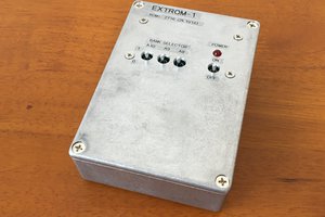
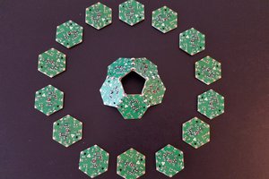
The PROM module EXTROM-2 is into a 15 cm x 10 cm x 4 cm aluminum die-cast enclosure as shown in Fig. 1. The circuit is mounted on a universal board and wiring was done by wire wrapping as shown in Fig. 2.

Fig. 1 PROM module EXTROM-2 connected PERSEUS-9
This module connects to the parallel interface of the PERSEUS series computer as shown in Fig. 1. This module has two 4kB banks and eight 2kB banks for each application software.

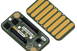
Fig. 2 Inside of the PROM module.
The application program is stored in a 2kB PROM 2716 as shown in Fig. 2. This PROM 2716 is a UV-erase PROM from around 1977, the same period as the LSI used in my PERSEUS series computers. The CI-2 application software was programmed into this PROM using PROM WRITER-3, which I recently made myself. The label name of the PROM in Fig. 2 is the file name of the application program. For example, the PROMs on the upper left contain the calculation of planetary position program CALC_PLANET_POSITION_02_5_3.
The circuit diagram of this PROM module is shown in Fig. 3. Here, the circuit is designed to be as simple as possible. The lower 7 bits of the PROM address bus are connected to the 7 bits of the 8-bit parallel interface, and the upper 5 bits of the address bus are generated by a binary counter. The MSB of the parallel interface is used to reset the binary counter, and the 8-bit data bus of the PROM is connected directly to the 8-bit parallel interface. The PROM bank selection is realized so that only the chip-select of the bank selected by rotary switch S3 is in the active state.
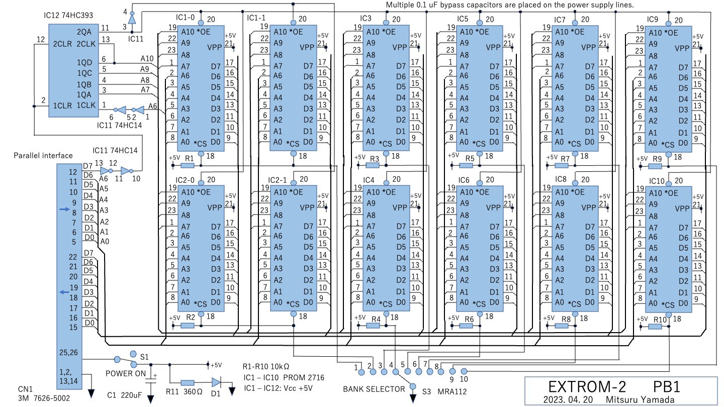
Fig. 3 Circuit diagram of the PROM module EXTROM-2
2. Software
Loading of the application program stored in EXTROM-2 is prepared as a command in CI-2. As seen in the second line on the LED display in Fig. 1, loading is performed immediately after typing ' at the command prompt. Here, the loaded program list has been shown on the display with the @ command. Application selection is made with rotary switch S3, on the panel in Fig.1.
Figure 4 shows this loading command addition portion of the CI-2 assembler source listing for the 6502 CPU. The top half of the list is the addition of the one-character parsing portion of the command line, and the bottom half is the loading execution portion from the parallel interface. The format of the information written to the PROM is the same as the ASCII code sequence of the CI-2 application program.
In this process, the binary counter IC12 of EXTROM-2 is first reset to zero. In the next iteration, the lower 7 bits of the 16-bit pointer are written to the parallel interface to determine the address of the PROM, the data output by the PROM is read from the read port, and the value is written to the RAM of the main unit pointed to by the pointer. The 16-bit pointer is incremented for each loop. The end of the program is detected by the end code % in the program text.
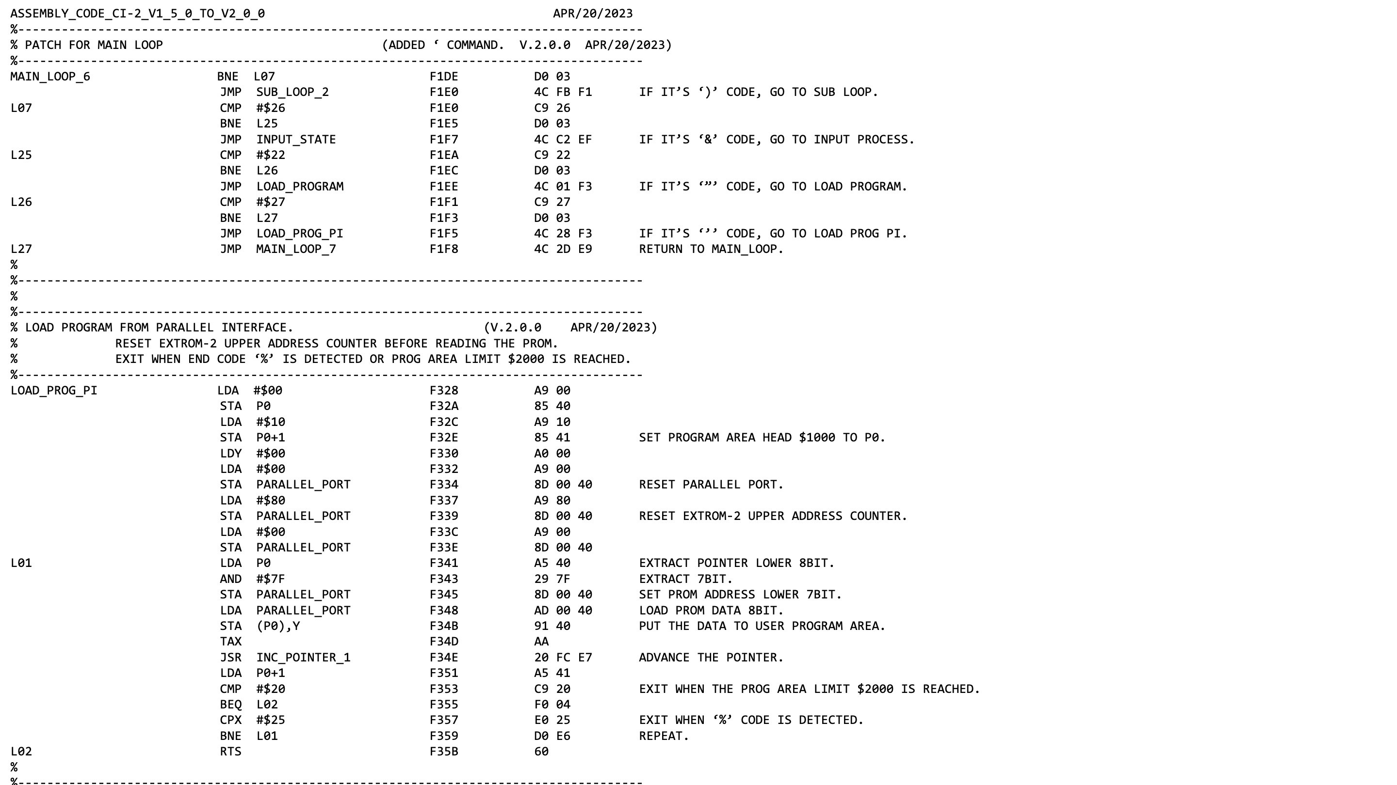
Fig. 4 Additional part of the loading command process of the floating-point interpreter CI-2
3. Results
This module has allowed the major application programs I have developed so far, such as listing memory dump, PROM programmer, testing elementary functions, Poisson distribution, Fourier transform, and calculation of planetary positions by Kepler equation approximation, to be evaluated immediately for execution. It would be important to refer to some representative application programs over time without changing them to check for differences in behavior due to interpreter version changes.
The power consumption of this module is 1W at 5V, 0.2A. The data rate for loading is 30 us/byte and the maximum loading time for a bank is 123 ms. The number of characters of one application software that can be stored in the larger 4 kB bank is 3840 characters. The entire module contains 22,000 characters. This is far less than...
Read more »
 Aightech
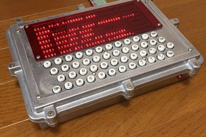
 Hexabitz
Why not use a single 27C256 ?