 Mark Omo
What is a Lock-In Amplifier? A Lock-In Amplifier is an instrument that is capable of measuring extremely small signals even those below the noise floor!
Lock-In Amplifiers are used in a wide variety of applications:
From remotely detecting changes in Rat Neurons
Creating low cost Cancer screening technologies
Next generation battery research
To Quantum Dot based Quantum Computers
To even Superconductor Research
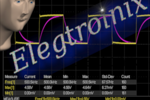
To see ours in action, check out this brief video:
How do they work?
Lock-In amplifiers use signal-processing tricks to simulate having an impossibly narrow filter to cut out the noise. Bandpass filters are described by how narrow they are as a function of their frequency. Q=(Center Frequency (in Hz))/(Band pass width (in Hz)). Generally, you can build practical filters with a Q factor of around 100 or so. But a Lock-In Amplifier can have a Q factor of 200,000 or more! 2 thousand times narrower! How can this be?
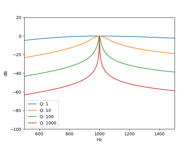
Well, Lock-In Amplifiers play a special trick! They shift the signal of interest down to DC, and it's very easy to build narrow filters at DC; just keep averaging! In fact, the Q factor at DC is zero! You can average for as long as you like to get an infinitely narrow filter (i.e., average for 10 seconds to get a 0.1Hz filter, 100 seconds for a 0.01Hz filter, etc...).
But how do they do this? by using some trigonometry. I hope you remember your trig identities! (don't worry no one does) If we multiply two sin waves, i.e.
We get the result;
A very special thing happens if x and y happen to be exactly the same! Our original signal splits in two, with half going to zero frequency (DC!) and the other half going way up in frequency (to twice the original frequency).
We can then use our trusty DC averaging filter to filter away the signal at 2x the original frequency and be left with a very narrow slice of the frequency spectrum right around the signal of interest!
Some smart-asses in the back are muttering about phase shifts and whatnot, well it turns out we can represent our sine wave as a vector on what's known as a Phasor Diagram (no unfortunately not a phaser, sigh). With a magnitude (or amplitude) and phase (or angle).
When we measure by multiplying the signal by a sin wave (0 deg phase) we are only measuring the X component of our signal, so all we do is measure again in the Y component (shifted by 90 degrees). This lets us calculate the amplitude (magnitude) of our signal, as well as it's angle!
Wait, why can't we just average a DC signal?
Well turns out that maintaining DC stability of voltages currents etc. without drifting at all is pretty challenging. It would also be easy for other DC effects to swamp the measurement and we can't remove them.
Consider the classic Lock-In experiment of driving an LED and measuring it in a photodiode. If we wanted to measure the LED's light output at 1 thousandth the brightness that we could see with our eyes or one millionth, in a brightly lit room it would be pretty challenging, trying to measure a delta of nanoamps on a milliamp signal is really hard. our output drifts by more than that if we move around the room.
But if we intentionally change the input signal to a sin wave we can "shift" it's frequency up and use our Lock-In amplifier to pick up just the signal from our LED!
Ok, so how do we make one?
Well, we need to feed the signal of interest into a multiplier, average the result and read it out. It's just that easy!
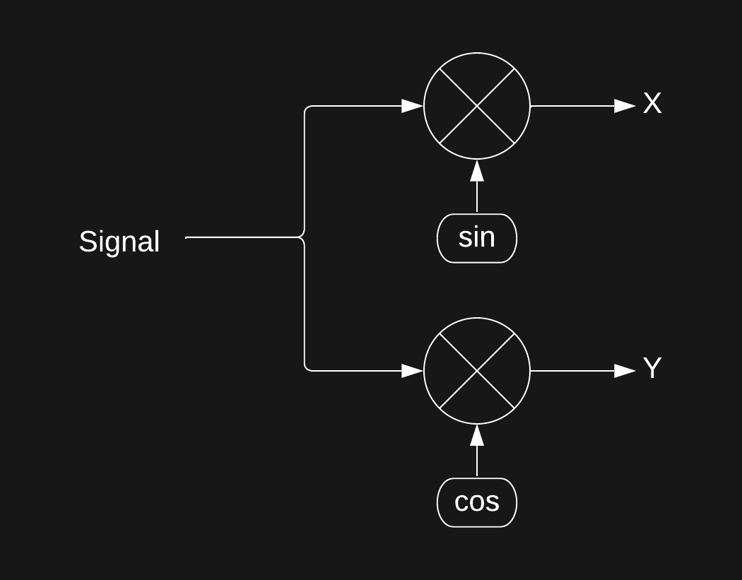
But wait you might say, where did sin and cos come from? and don't they have to be exactly the same frequency as our signal for this to work?
Well... turns out real systems are just a little bit more complex...
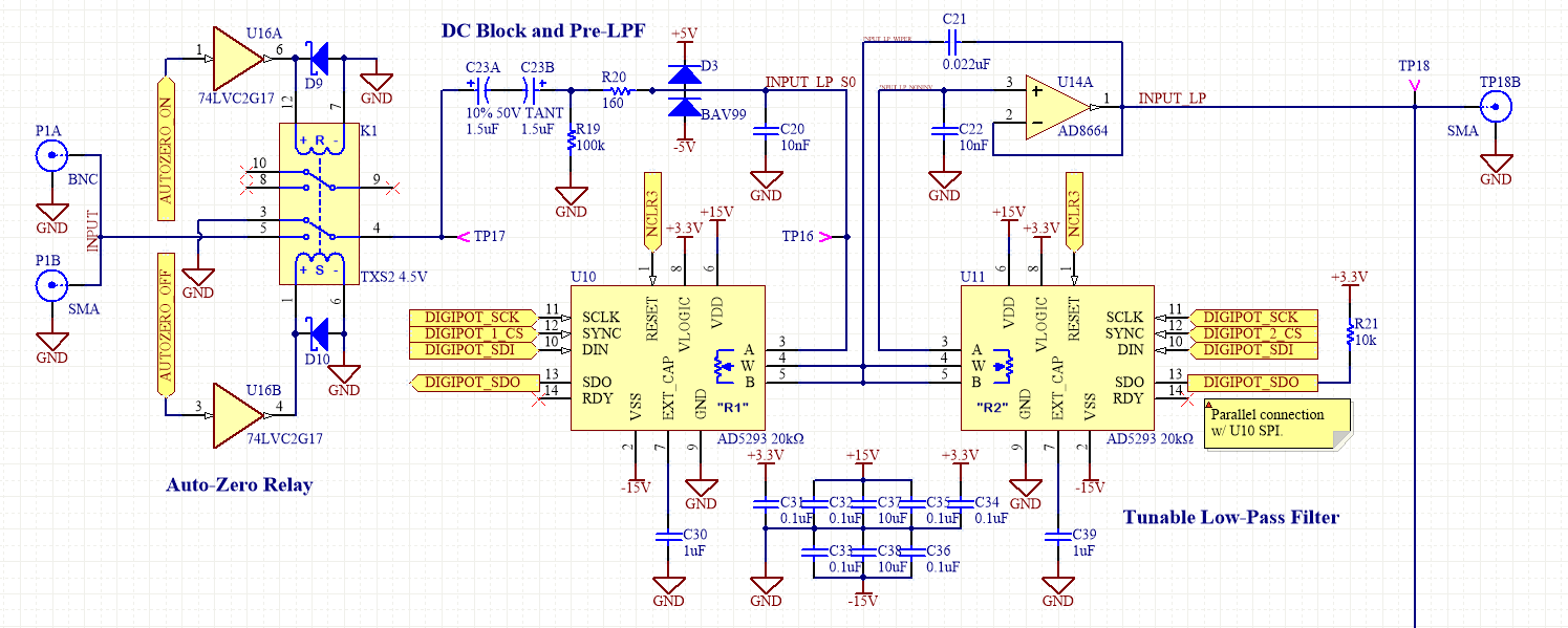
This is the system we designed! Chock full of Op-Amps.
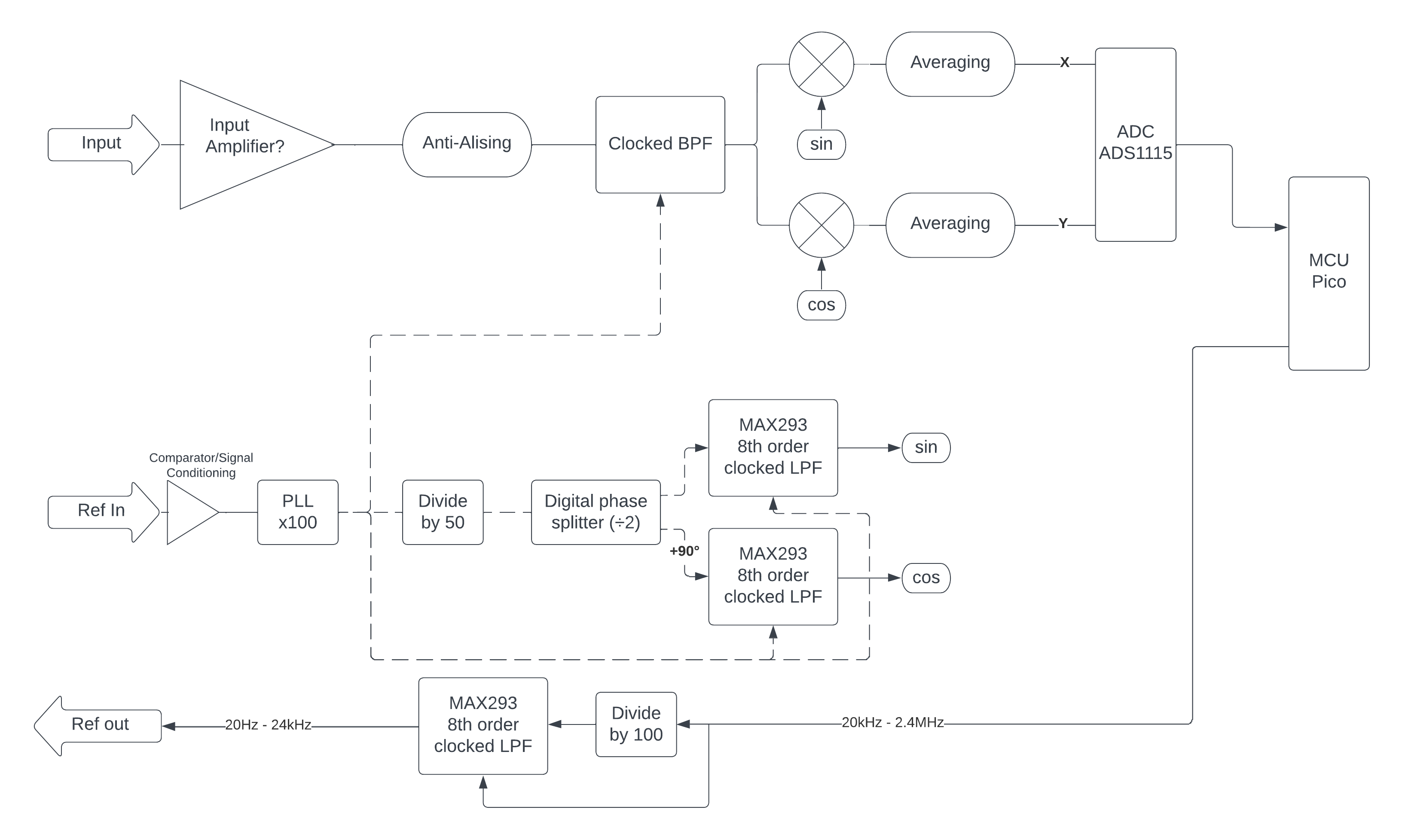
Check out our blog posts on the circuit design!
It includes no less than 9 Op Amps, 4 old school clocked analog filters, three digi pots, and two analog multipliers and is capable of measuring signals with a...
Read more »

 Ringo2k
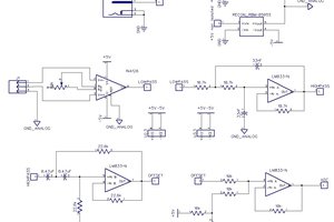
 Jesse
Jesse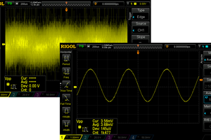
 RoGeorge
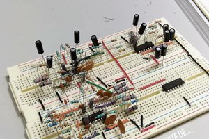
 Lilia Lobato