 Mark Omo
The first part of our schematic consists of a tunable low pass filter and a tuned bandpass filter.
The very first part is the tunable low pass filter; it's used to remove frequency content above the frequency of interest and to prevent the aliasing of the filters.
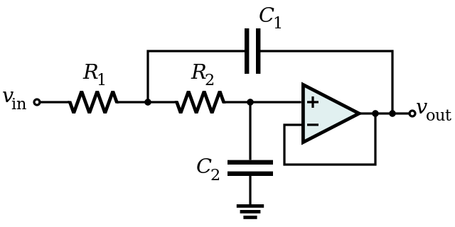
It's a classic Sallen-Key filter, with an RC filter on the front and variables R1 and R2.
Sallen-Key filter (from Wikipedia):
Our implemented design input and filter design:
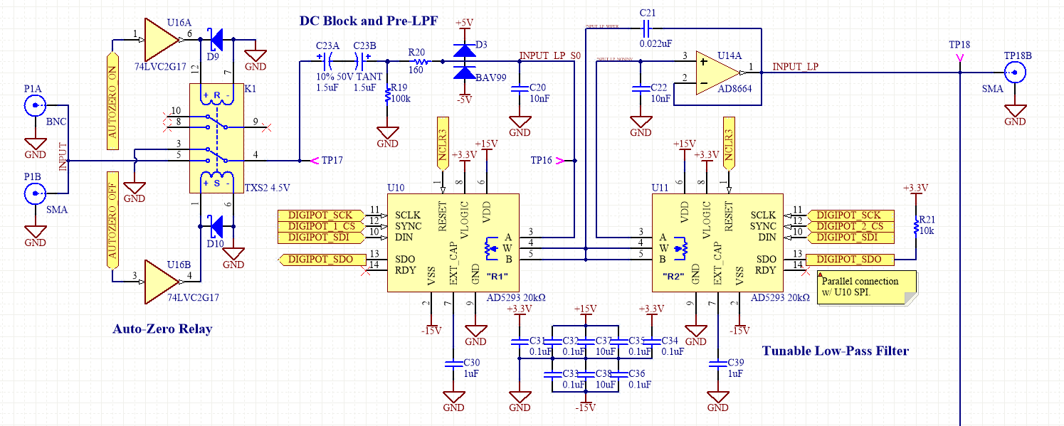
First up is an auto-zero switch. It allows us to short the input to the signal chain and cancel out all our offset and gain terms from the system.
Next up is a DC block filter, Lock-In amplifiers don't operate on DC signals so getting rid of them early lets us accept signals with a lot of bias, and simplify our signal chain.
After that is our Low-Pass Filter. We used an AD8664 Op-Amp for the Sallen-Key filter; it's a low-noise part with plenty of bandwidth for our application. The bandwidth is critical for active filters, active filters can only reject signals out to the bandwidth of the op-amp, beyond that the op-amp can't react fast enough to counter signals. That's why we have a pre-filter to cut out signals that are far away from our signal.
We used AD5293 Digi-Pots for the variable resistors. The main advantage of these parts is that unlike other Digi-Pots with 20-30% or more variation of resistance, the AD5293 is calibrated to have better than 1% variation, allowing us to get a precise filter response.
Next up is our Tunable Band-Pass filter:
Traditionally tunable filters are very challenging and complex, especially over a very wide input range. But the LTC1068 is a very special kind of part, it's a Switched Capacitor Filter. Their filter coefficients are set by a clock input, switching charge into and out of very small matched capacitors on a chip. This lets us have a very precise filter response that is precisely controlled by a clock input.
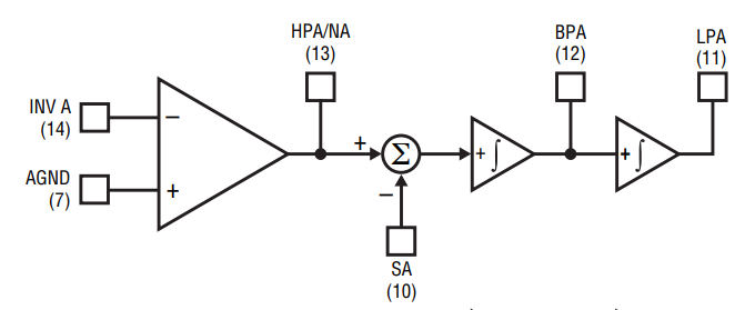
The LTC1068 has four filter sections in a configuration known as a "State-Variable-Biquad". We can break down that term into two parts, "State-Variable" means that we can vary its operation (in this case with our clock input), and Biquad, which is a single seconds order filter, that can be hooked up to form any kind of filter.
Here is a block diagram of a filter section from the LTC1068's datasheet:
But how can switching capacitors let us realize a filter? (A great resource, paraphrased below is this PowerPoint by Dr. Jennifer Hasler at Georgia Tech) Well the first step is to realize that a capacitor switching back and forth can act just like a resistor:

The Capacitor will fill up with charge when connected to V1 and then dump that charge when connected to V2, transferring some charge. The rate at which it transfers charge is related to the size of the capacitor and how fast it's connected to V1 and then V2. And what do we call a transfer of charge? Current! It turns out the charge transfer is proportional to the switching frequency, capacitance, and difference in voltages. Resistance is just the Voltage difference over the charge per second. So switched capacitor has an equivalent resistance of:
The nifty thing is we can precisely change the equivalent resistance, and it does not have the disadvantage of drift and tolerance over time, especially if you cleverly use only the ratio of the resistances on an integrated circuit.
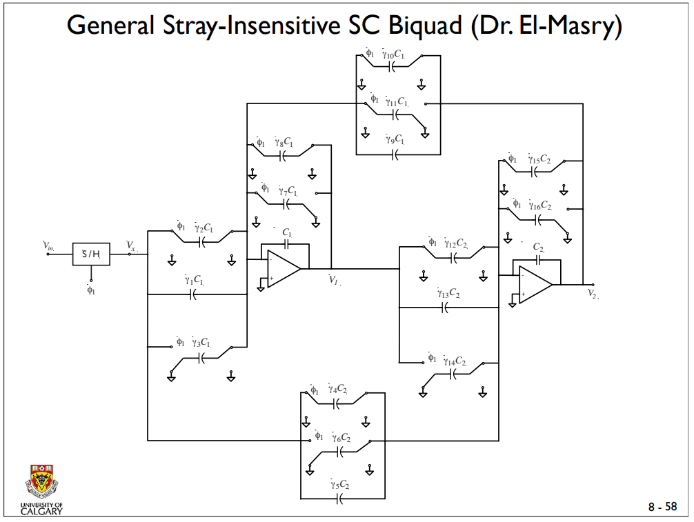
This allows us to construct a biquad filter section that can be tuned across a wide range of frequencies:
Resources:
Discussions
Become a Hackaday.io Member
Create an account to leave a comment. Already have an account? Log In.