 MaxBlack
There are lots of LED Music Spectrum Electronic DIY LED Flash Kit available in the market, this is a DIY Music Spectrum using NeoPixel RGB LED Matrix and ARM microcontroller. A control panel is fabricated on PCB for this project, check out the whole process below and see this Colorful Music Spectrum in working in the Video given at the end.
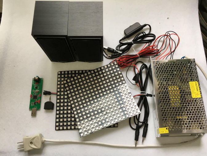
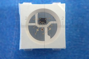
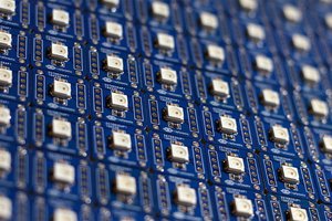
Materials Required:- Flexible 16x16 NeoPixel RGB LED Matrix *2 (link to buy)
- Core Board (PCB by EasyEDA)
- Switching power supply, 5V 40A.
- Audio Line*1, 1 min 2 audio interface*1, Speakers*1.
How to make a LED SPECTRUM ANALYSER
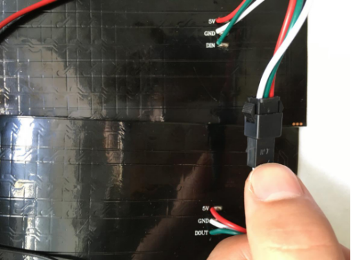
Step 1) LED Connection:
Connect two 16*16 RGB LED matrixes by connecting DOU interface of the first LED matrix to the DIN interface of the second one, that’s make a bigger 16*32 RGB LED Matrix.
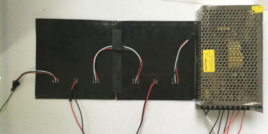
Step 2) Power Connection:
The operating voltage of my LED Matrix is 5V, so I would like to connect two LED power interfaces into an outlet of a 5V control power. Please take a note that the maximum current of a working LED is 18A, so it is recommended to use an over 40 A control power and choose a thick enough wire to connect it.
Step 3) How to make a Control Panel:
A control panel is to receive audio signals which are processed by FFT and then transported to LED matrix display. The controlled LED is a dot-matrix programmed by WS2812b, whose controlling signal frequency is 800KHZ. The timing-controlling diagram is shown as below,
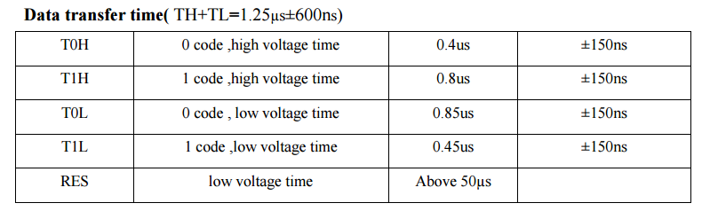
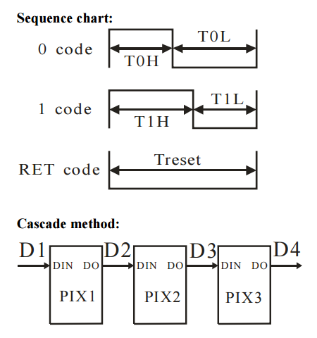
Each LED is controlled by 24-bit data with its structure of G7~G0+R7~R0+B7~B0. The data is sent by the principle of higher place first and in accordance with the sequence of GRB.
An amplifier circuit using LM358 has been used in this Music Spectrum as shown below:
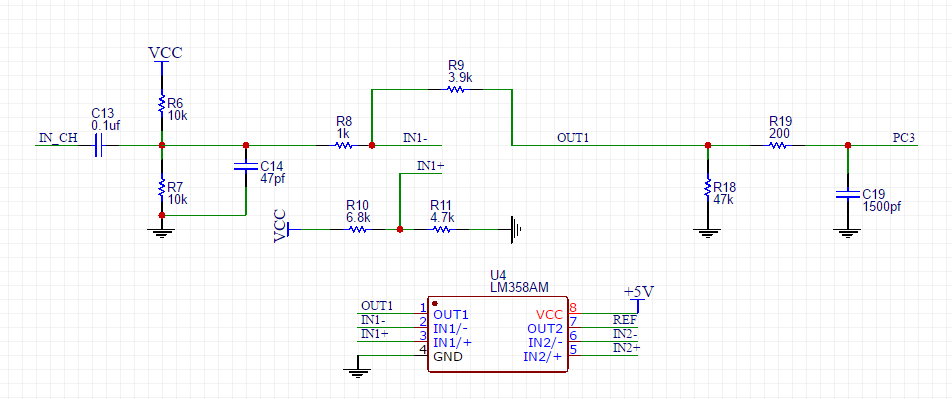
In the diagram, IN_CH is an audio access terminal of a computer and PC3 is the amplified output signal which has been further sent to STM 32. C13, R6 and R7 are grouped into a signal-strengthening circuit, which can raise the signal voltage and turn a negative voltage into a positive one. The circuit following R8 is signal-amplifying one, with its signal strength of PC 3 equal to R9/R8 times of the previous signal before R8. IN 1+ is the end to set the minimum voltage value output from OUT 1.
Here we recommend using EasyEDA to design a control panel. EasyEDA is simple and efficient online EDA designing software, by which you can draw a diagram or cut a pattern conveniently. In EasyEDA, the database for the components is huge! You can easily select some of the basic components on the left of the page or search hundreds and thousands of components in their library so it is very easy for you to find what you needed.
Following is the link of my complete circuit diagram and PCB layout, where you can see it very clearly.
https://easyeda.com/vividz/DIY_LED_Audio_Spectrum_Analyzer-7e06e9e5808d48bab1953590aa3c2e9f
You can also register an account there so as to download my diagram directly into your account.
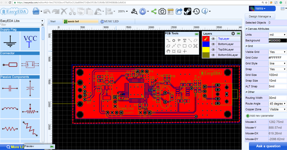
Below is a screenshot of PCB layout of LED Music Spectrum circuit from EasyEDA:
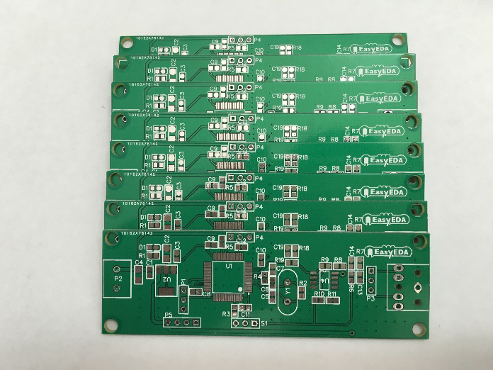
After finish designing PCB, I have ordered some PCBs form EasyEDA. I am pretty happy with the boards I received, and the price was good.They all works well.
If you like it, you can use my PCB order this led spectrum analyzer.
Step 5): Welding and Connecting
After components are welded the way the following screenshot is shown, a control panel is completed. It’s very simple.
Connect the computer audio cable into the beta version of the welded interface, and then open the computer music. It is possible that you may not hear any sound of the computer music after inserting the audio line. Under such circumstance, we can use a 1-turn-two connector to transform the computer audio output into two channels output. One channel is connected to the core-board while the other to a speaker.
In the diagram shown above, a core-board is powered by a computer USB and connected by an audio output interface. The other interface of the computer audio output is connected to an external speaker. It is feasible when the signal line of the lattice-control...
Read more »


 Jercio-sk6812
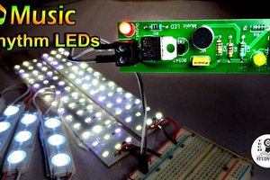
 Subhajit
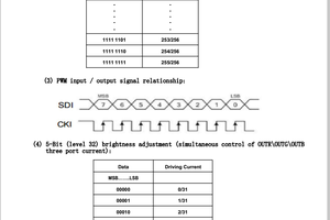
 Hugo
Hugo
nice design..how about APA107 led source for this display? maybe it is better