 Hamza Deniz Yılmaz
Power supplies are the basic components that provide the correct voltage and current required for the operation of electronic devices. The voltage and current required for electronic devices often vary, so power supplies must provide output voltage and current that can be adjusted to suit different devices.
In this project, a list of components required to make a power supply is given. These components include a voltage regulator, several diodes, several resistors, several polarized capacitors, several potentiometers, and a switch that provides the 12 volts DC output voltage necessary for the operation of many electronic devices.
The power supply design begins in the first step with the use of a rectifier circuit to convert from an AC power supply to a DC power supply. The diodes (D1-D9) used in this circuit convert alternating current (AC) to direct current (DC). At this stage, the use of a filter is necessary, since the output voltage has not yet been regulated.
For filtering, a polymeric electrolytic capacitor was used, using capacitors C1 and C2. These capacitors are used to clear the DC output voltage from unwanted noise and ripples.
Then, the output voltage is fixed using the voltage regulator (U1). A voltage regulator named V_REG_317SINK was used for this project. This voltage regulator uses a potentiometer (R4) to adjust the output voltage to the desired value.
The potentiometer allows the output voltage to be adjusted to the desired value. The R4 and R5 potentiometers are used to fine-tune the output voltage of the regulator. Thanks to these settings, the output voltage can be adjusted precisely to the desired value.
Several resistors (R1, R2, R3, R6, and R7) are used to control the operation of the circuit. These resistors are used to properly direct voltage and current.
A power supply is an electronic circuit that provides the electrical power required for the operation of electrical devices. This circuit is designed to convert AC voltage to correct voltage, and this correct voltage is the power supply required by electronic devices.
This power supply circuit consists of many different components. These include polarized capacitors, diodes, transistors, resistors, and a voltage regulator. Capacitors are used to reduce the noise generated during the operation of the circuit and to provide a smooth DC power to the voltage regulator. Diodes are used to convert AC voltage to correct voltage, while transistors and resistors are used to ensure the stability of the power supply circuit.
The voltage regulator used in the power supply circuit fixes the output voltage at a certain value. In this way, fluctuations in the output voltage are minimized and electronic devices operate more safely.
The power supply circuit can be used in many different electronic devices. For example, many different devices, such as computers, televisions, sound systems, and smartphones, have power supply circuits.
A rectifier circuit is used in the power supply circuit to convert AC input to DC output. In this circuit, C1 and C2 are polarized capacitors. C1 has a capacity of 2200uF and has a voltage resistance of 75V, while C2 has a capacity of 10uF and a voltage resistance of 75V.
Other components from D1 to D9 are 1N5408 and D8 1N5400 series diodes and are used in the rectification circuit. These diodes pass AC signals in the right direction but not in the opposite direction. Thus, the AC input is converted to a DC signal.
Q1 in the power supply circuit is a TIP127 type PNP transistor and is used in the regulator circuit. R4 and R5 are resistors in the regulator circuit with 2.5kohm, 1W bi-level 16mm potentiometers.
A voltage regulator named U1 V_REG_317SINK is used in the regulator circuit. This circuit stabilizes the output voltage at the desired level. R6 are 100 ohm, R7 10k ohm, 1W resistors and they are connected to various parts of the circuit.
The S1 is a 320-938 toggle switch that turns the power supply on and off. J1, J2 and...
Read more »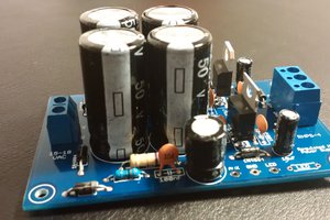

 hesam.moshiri
 Hasan Murod