 kelvinA
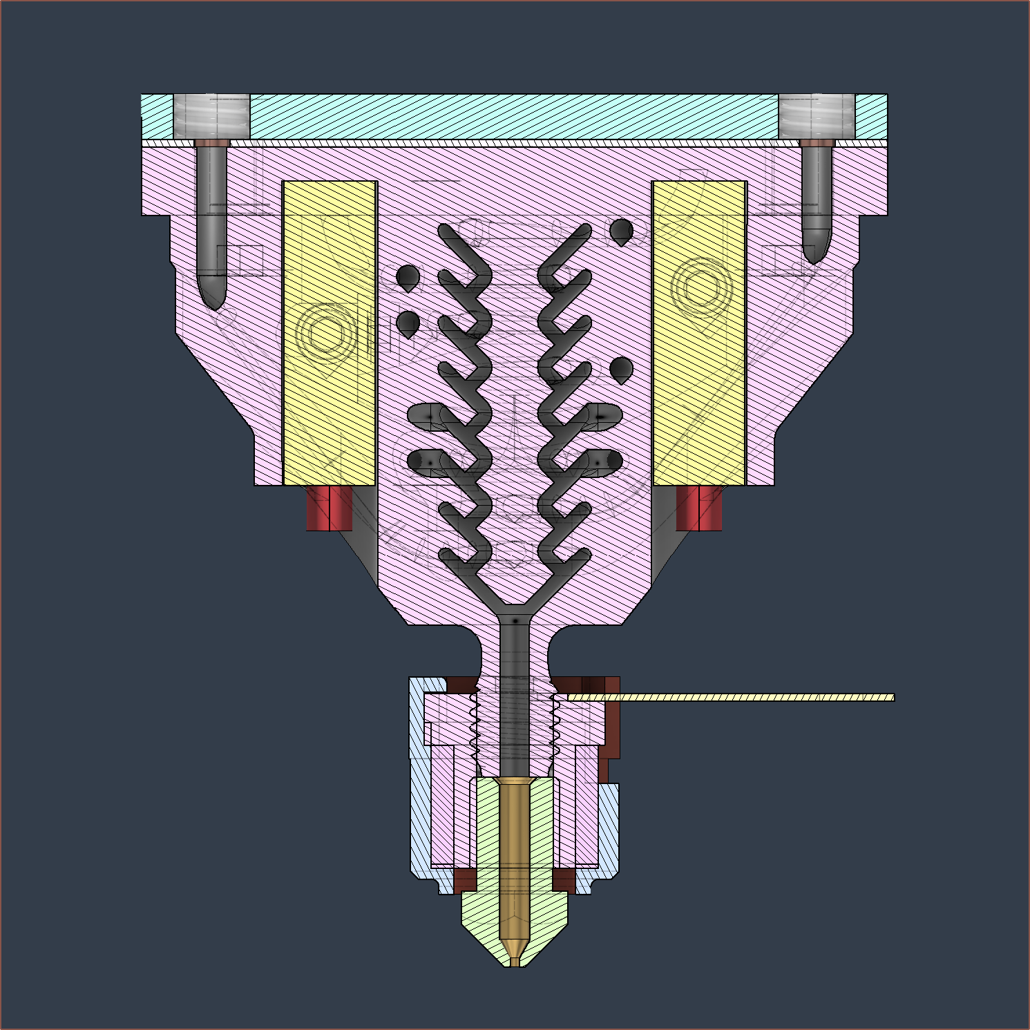
Because I was trying to find more information about Construct3D's custom heatblock design that is targetting 200mm^3/s, I started listening to a podcast and one of the things that Jacob mentioned was "intent", describing how the quality of his Minecraft server building designs had much more quality when he had to struggle in Survival Mode to get every block, compared to Creative Mode when he has unlimited everything, and he subsequently brought this idea of intent over to his 3D printer design methodology. Now that I've got a new heatblock design and every millimetre of it has been questioned multiple times, I've been thinking of the similarities to Jacob's talk of intent.
Firstly, some quick changes that have happened in the design:
- MinorChannels are now 1.75 * 0.75 + 0.2 -> 1.5125mm.
- I've reduced the length of the thread and now it is 10mm (down from 12mm in R0).
- The height of the heatblock is now 41.5mm, which is about 10mm reduction from R0.
- The heatsink thread holes are 2mm from the edge, which should be ok.
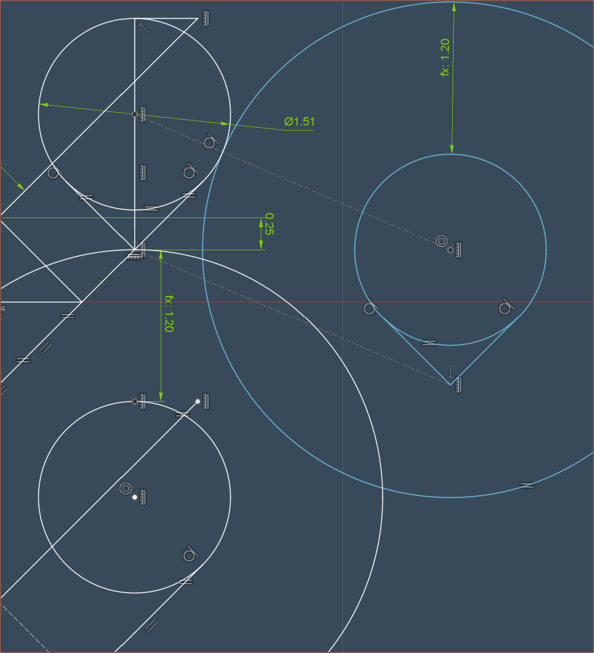
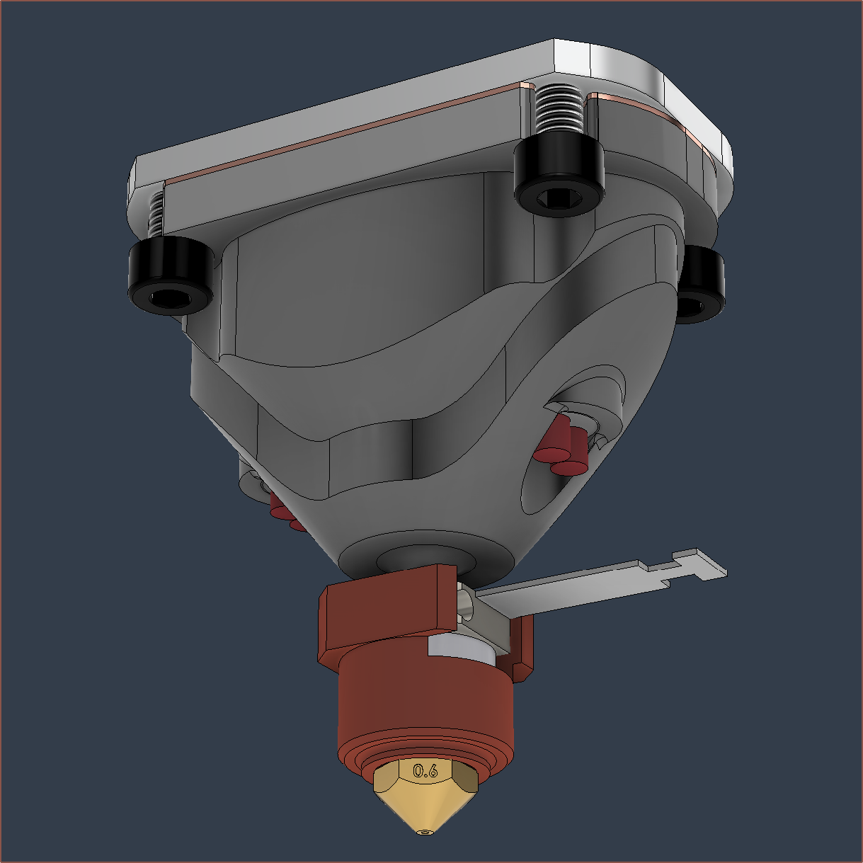
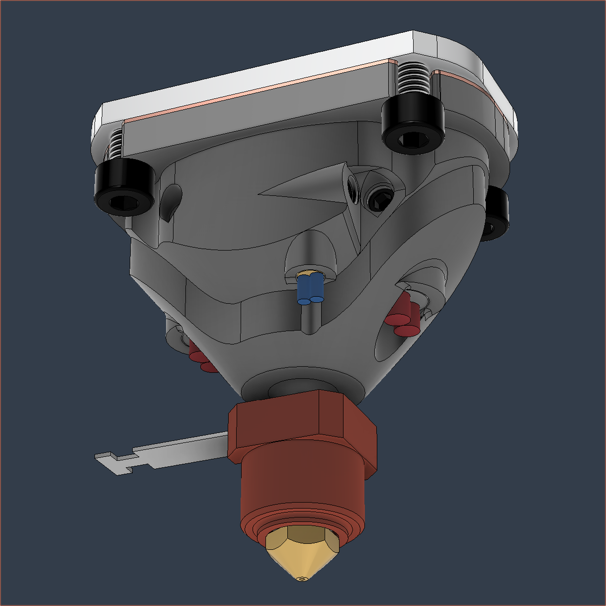
Centre Pillar
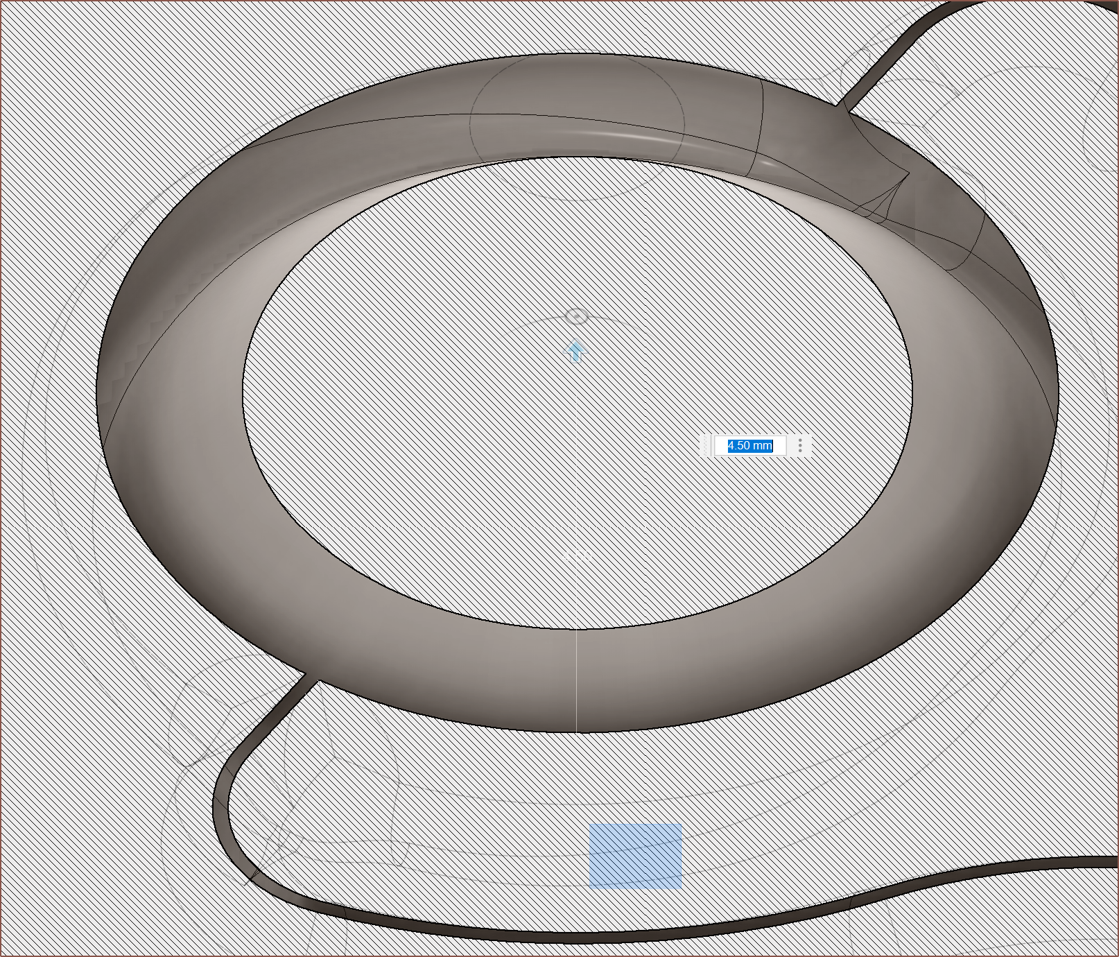
The main profile is shown below:
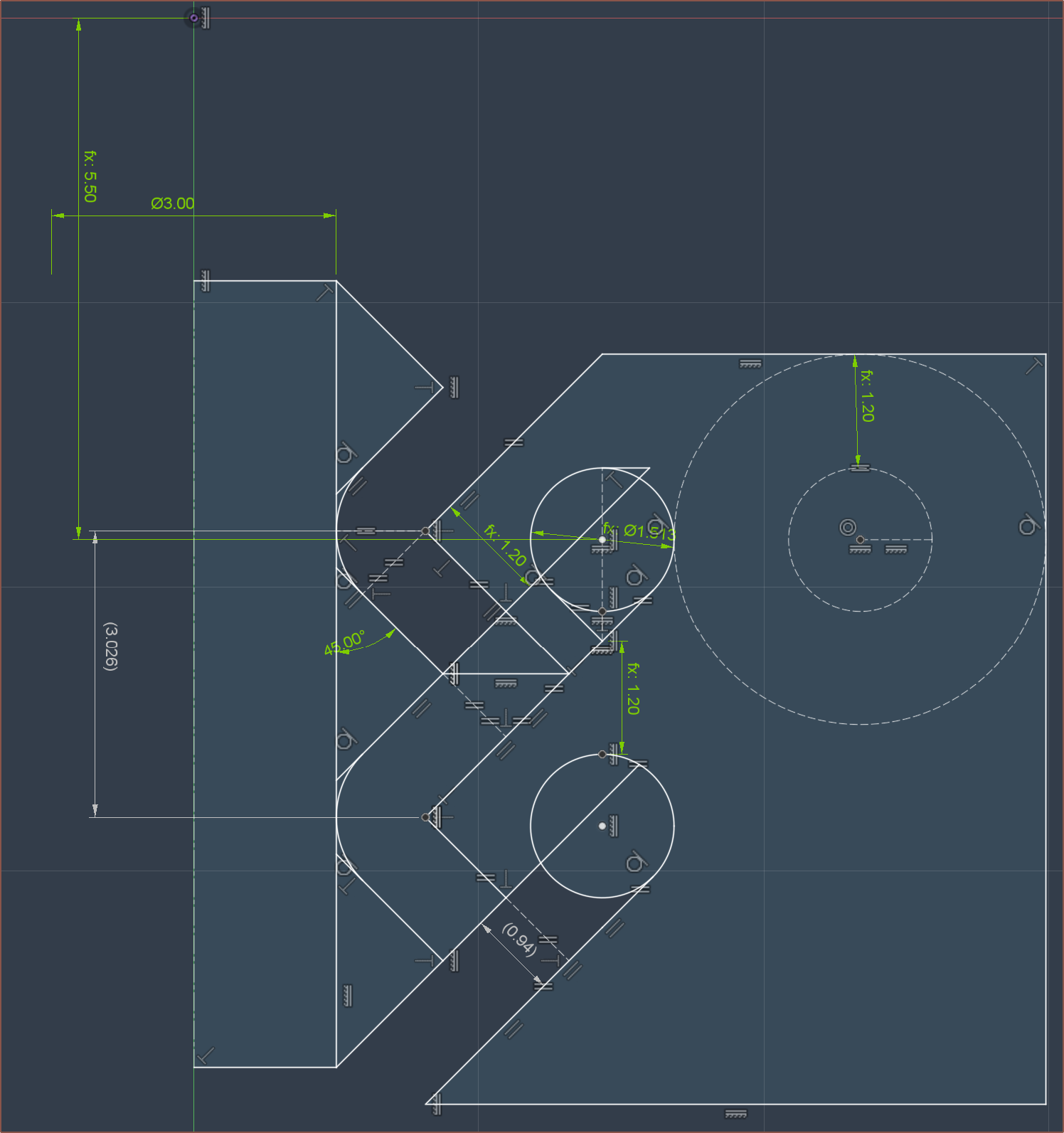
For weeks, I've been wondering if I should change the 0.95mm spacing, but I felt that I didn't want to even change it by more than +/- 0.05mm so I left it. Well now the geometric laws have spoken, and by ensuring a minimum wall thickness of 1.2mm, the spacing is precisely 0.94mm.
Additionally, the centre pillar now has a much more active role in forming the extrudate instead of being there just because I hope it has a positive effect. As the fluid inside the heatblock is incompressible, the idea is that a push/pull of material will move this 3D revolve of the triangle between the 2 inputs:
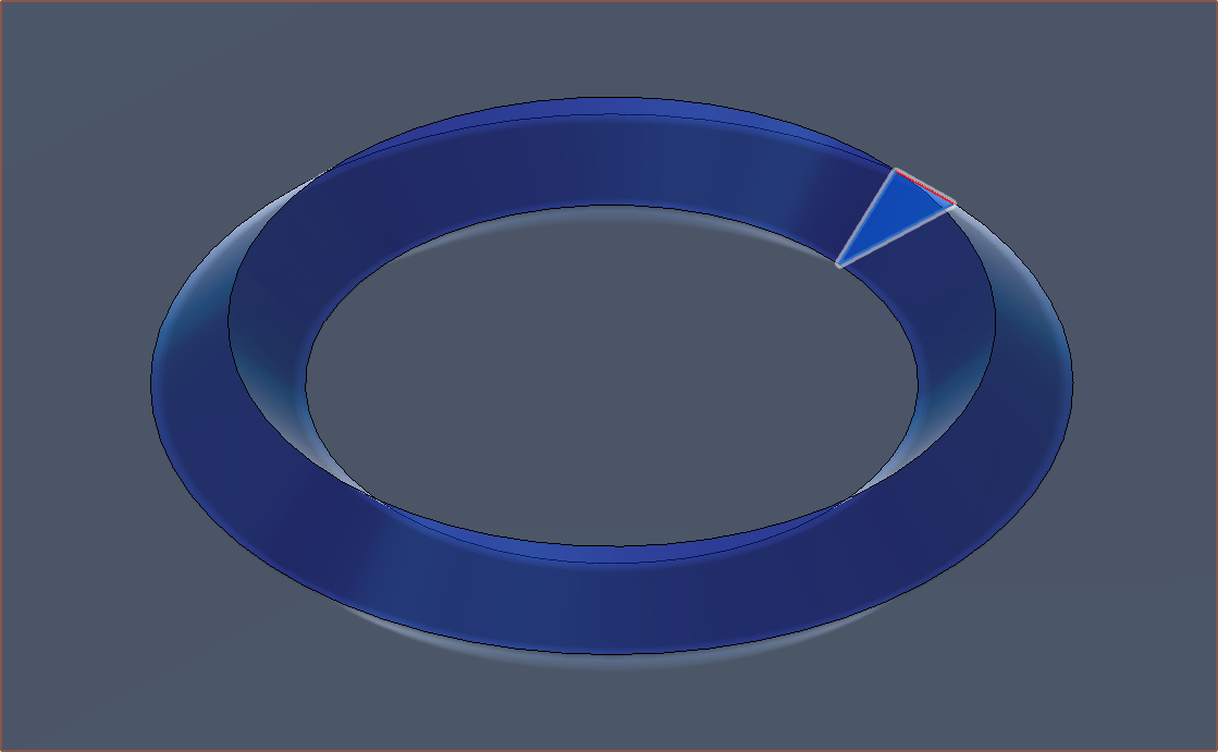
The volume of this is 9.118mm^3, and the push/pull length can be found as follows:
( 2 * [purge volume] / ( pi * [filament diameter]^2)
( 2 * 9.188 / (pi * 1.75^2) )
= 1.91mm
I had set my push/pull length for the c8or r0 to be 1.8mm, so I'm doing great on these guestimates.
I'm hoping that this new geometry both gives more time for the cone-ring-CSA to equalise in pressure, reduce the diffusion-area between different materials and make the flow interactions more forced.
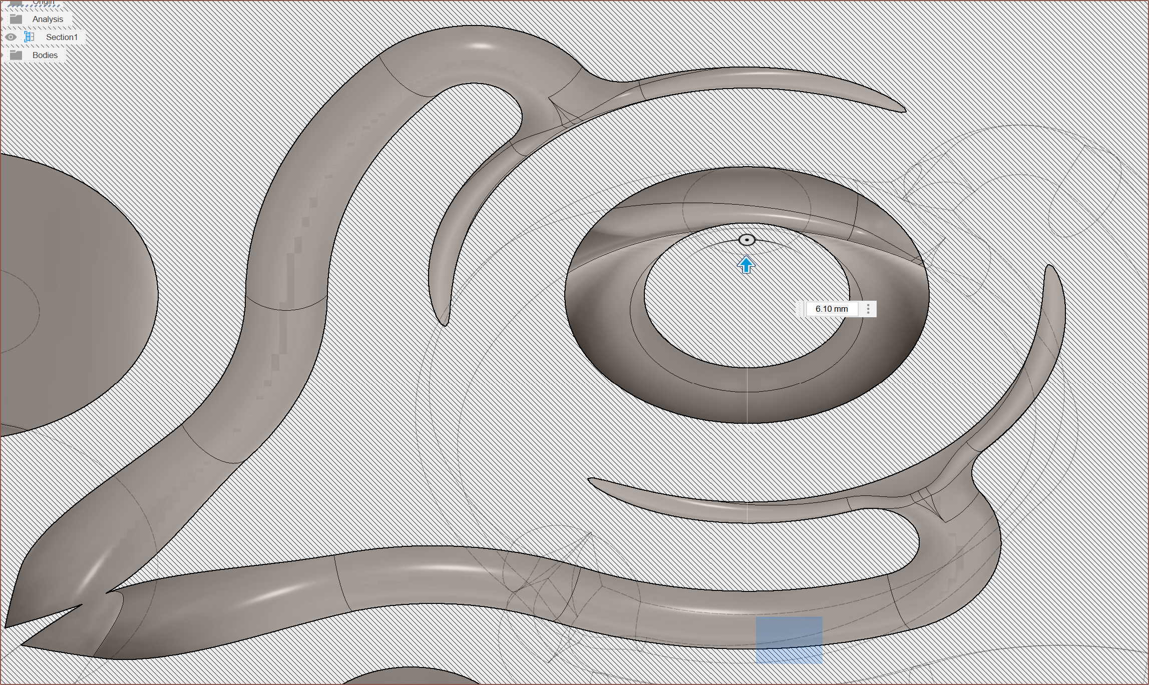
Pathways
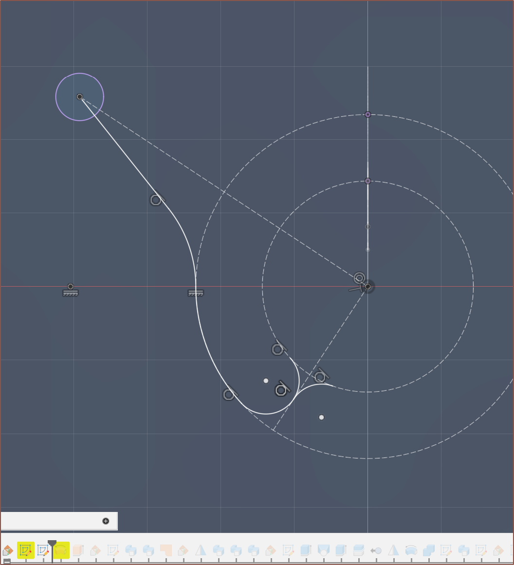
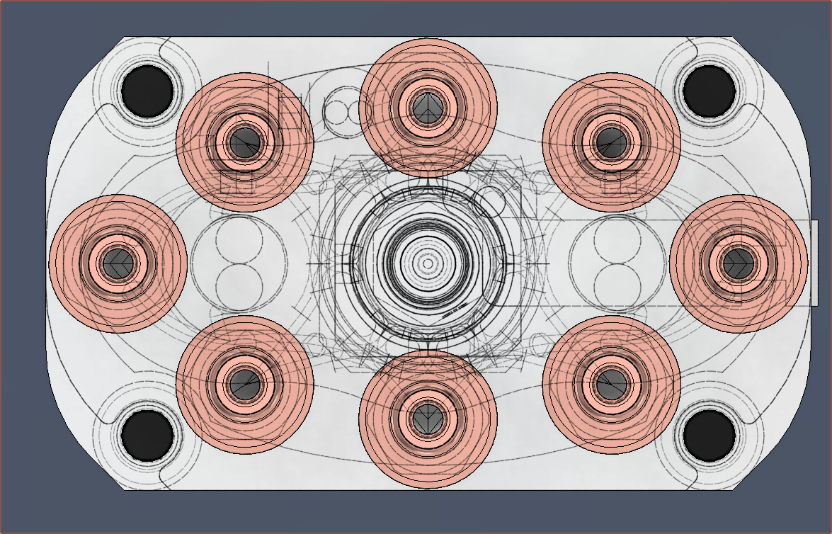
As the aim is to get consistent 360 degree pressure and the crosshead designs I saw yesterday weren't doing any centrifugal-like geometry, I've gone back to a simpler design with 2 inputs. I had considered 3 inputs but feared about pressure propogation delays and how channel 7/8 may have a different pressure profile than the other 6 since I can't just go straight through the heater cartridges. The sketch is shown below:
Well, that's half the reason. I was forced into it because the staggered approach caused minimum-wall-thickness violations.
I then tried some conic curves to transition from the minor to major channel, mainly so that channel4 was more spaced from the paths of channel7.
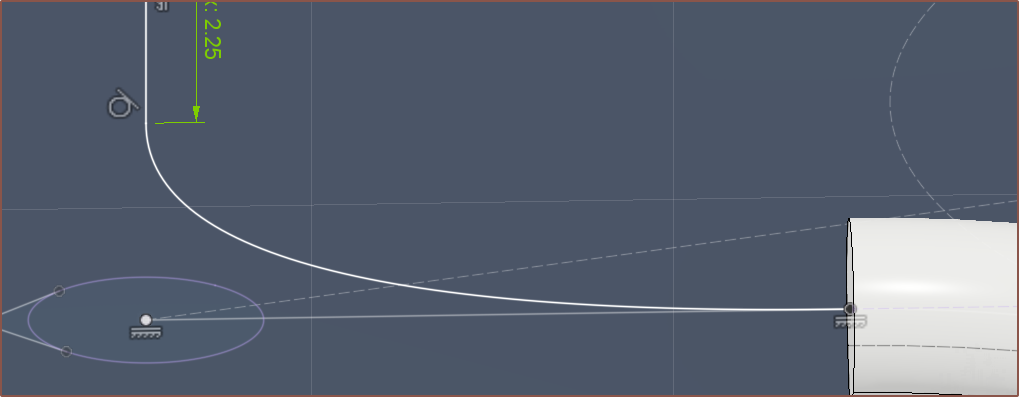
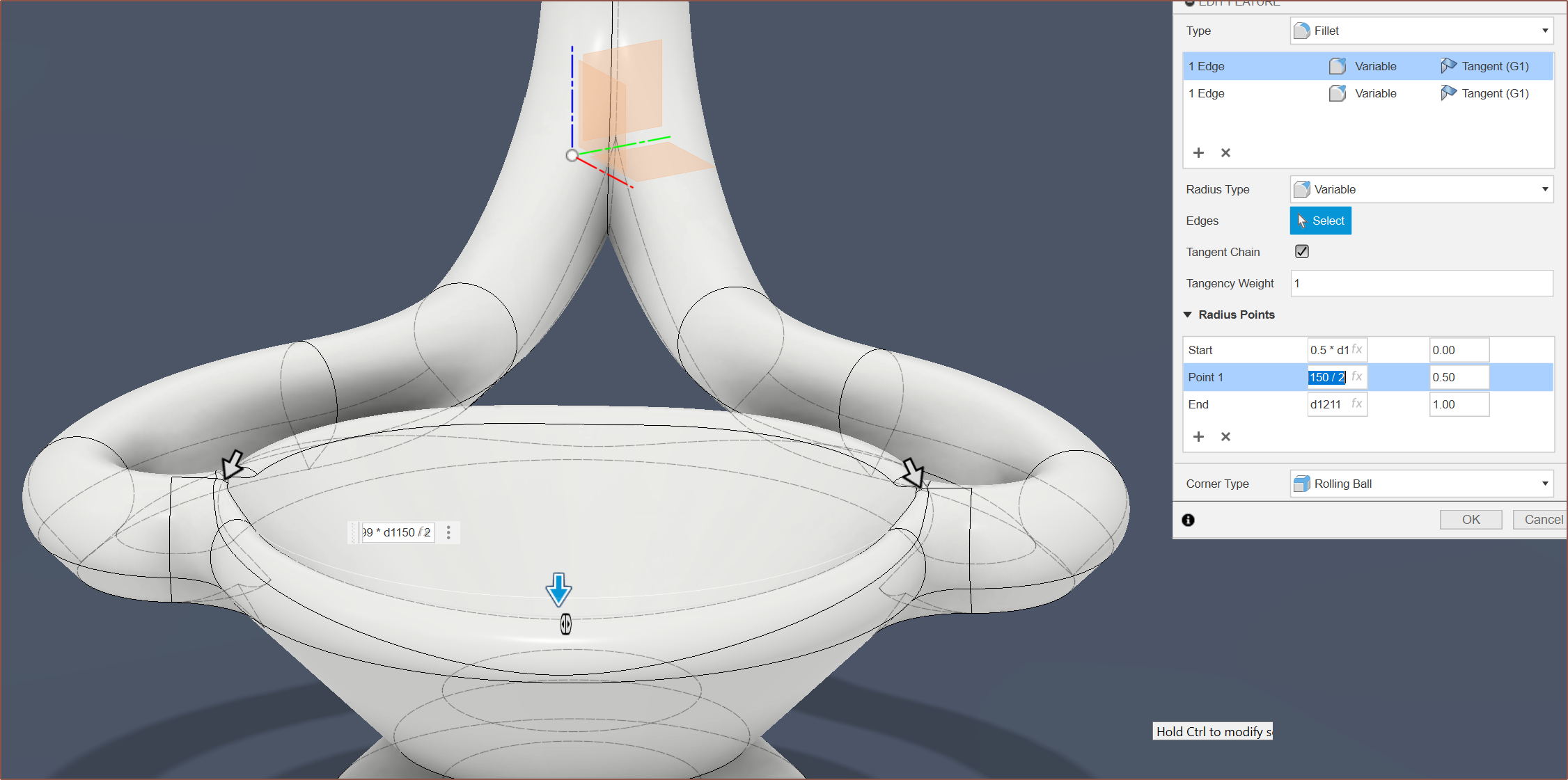
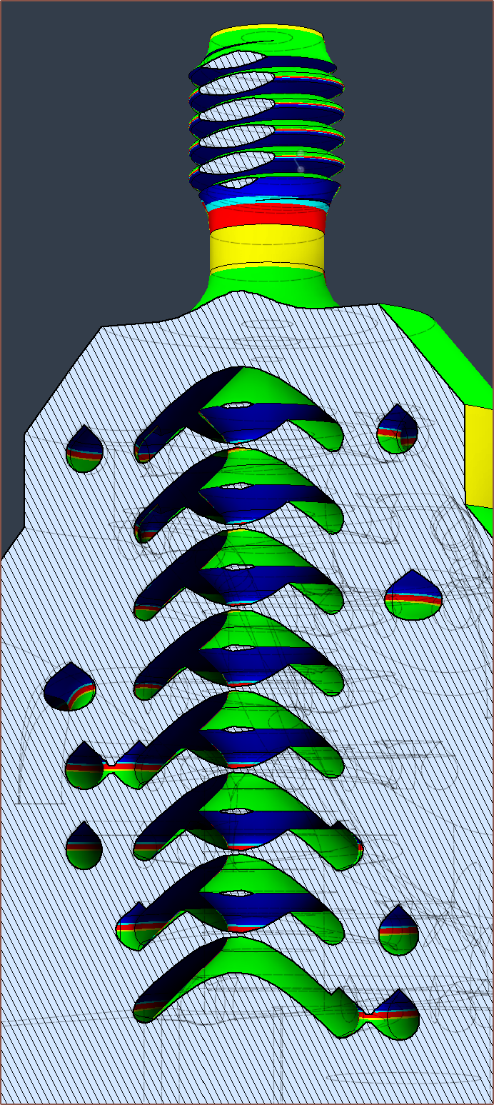
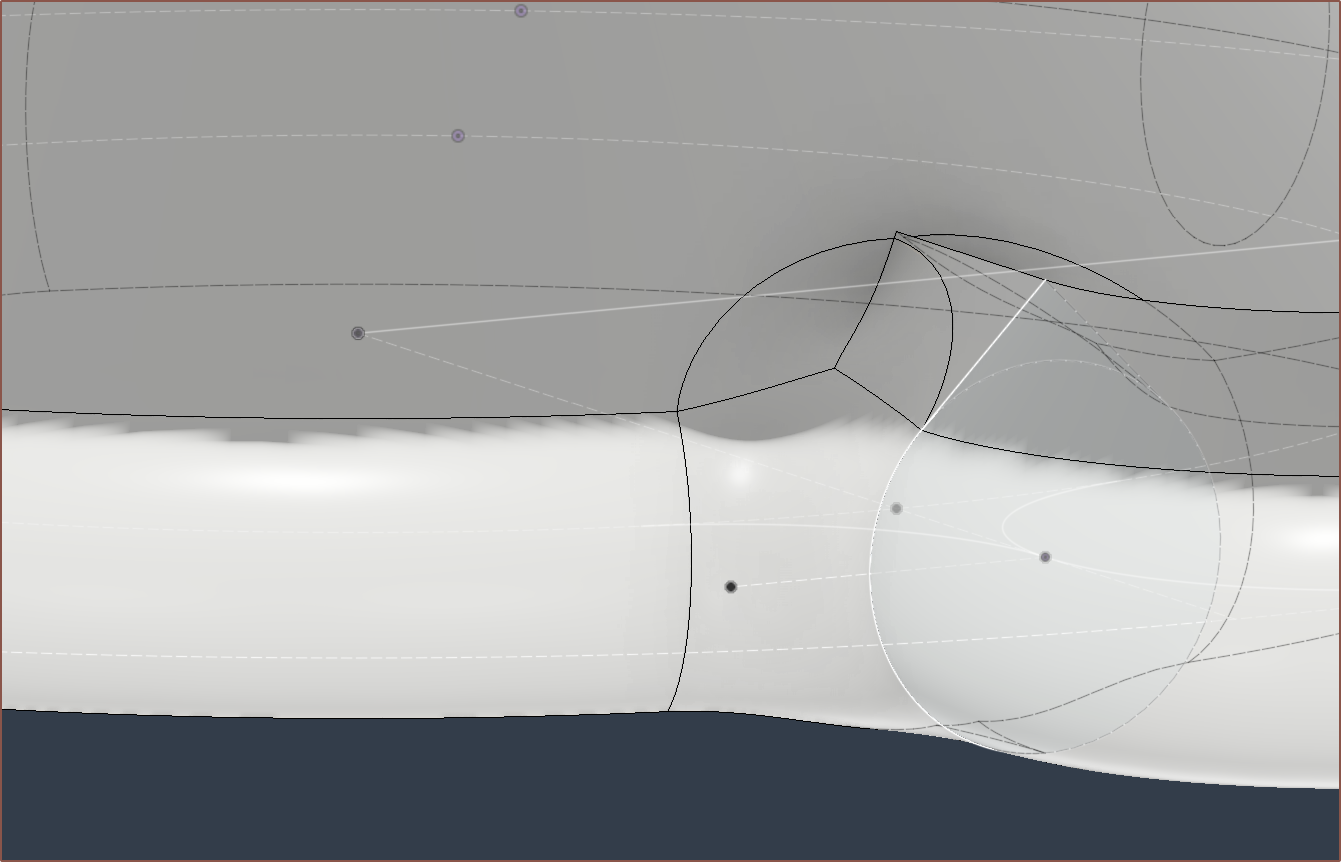
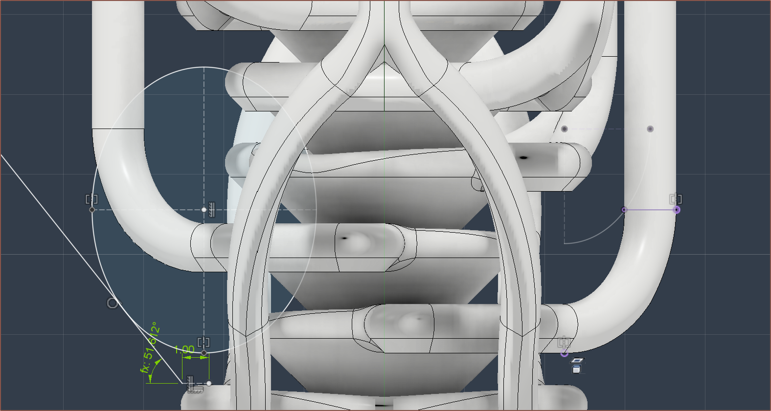
I did the revolve and then made this fancy variable fillet which aims to keep the pressure more constant as material moves further away from the inputs:
About 2 more hours of fixing later (which didn't help since Fusion decided to delete some features and sketches instead of just making them yellow or red) and I had the new geometry implemented. Almost everywhere was >=1.2mm minimum wall from what I could tell.
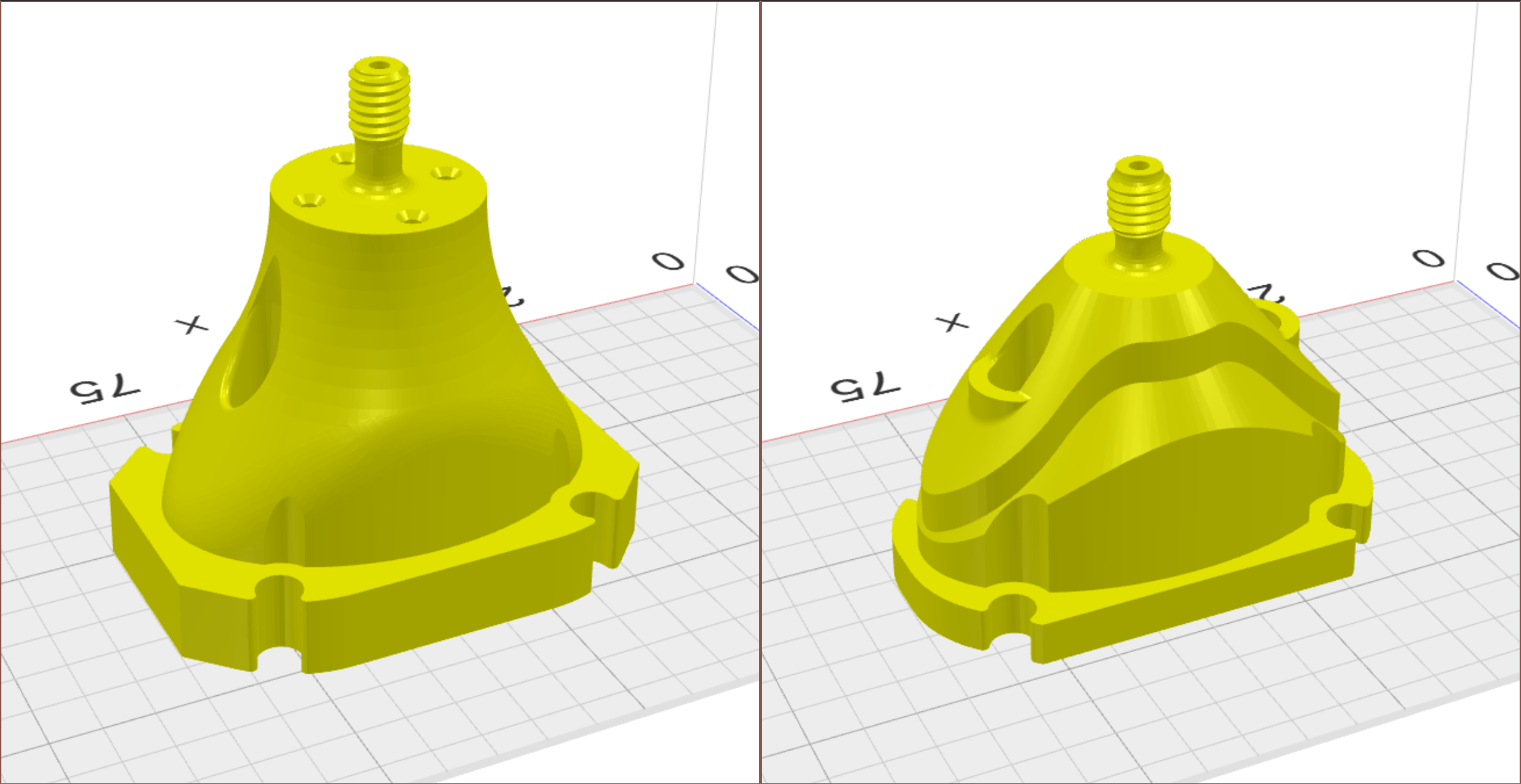
The heatbreaks go right to the edges of the bounding box, but I was still able to keep the 29 x 49 XY size.
Next-day fixes
First I tried something called draft analysis as I was hoping that I could use it to see overhangs over 45 degrees, but it seems limited in that it's only optimised for injection-moulding workflows and, as such, I can't set anything over 15 degrees.
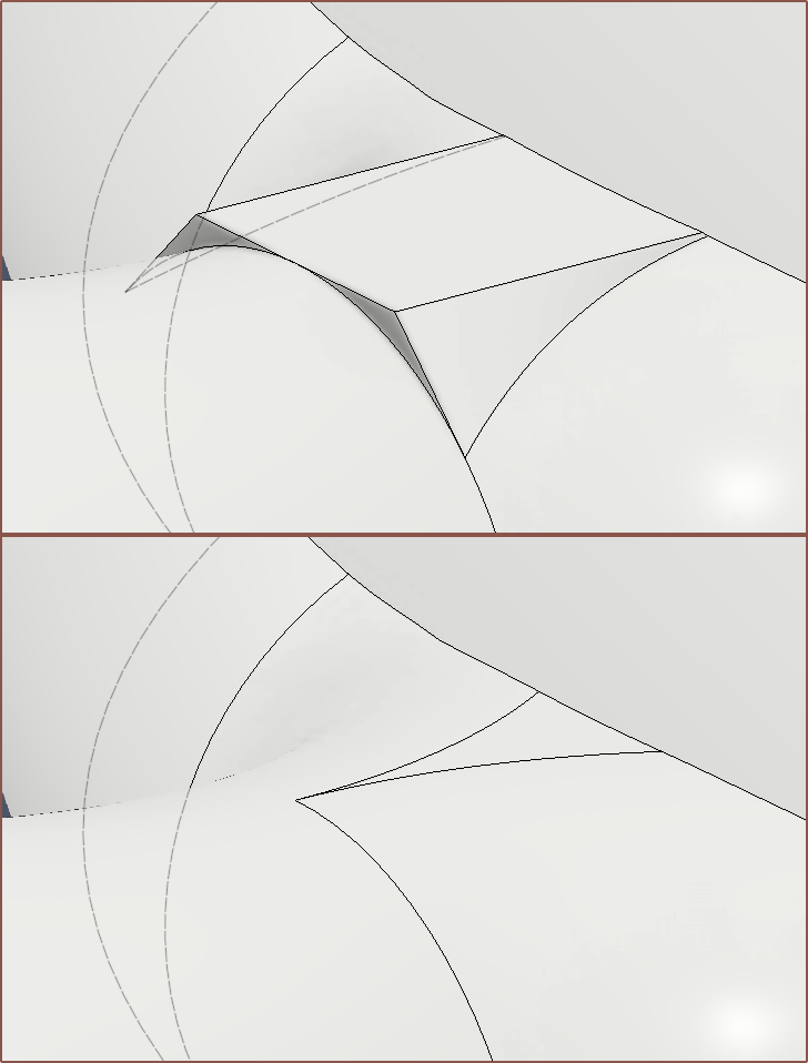
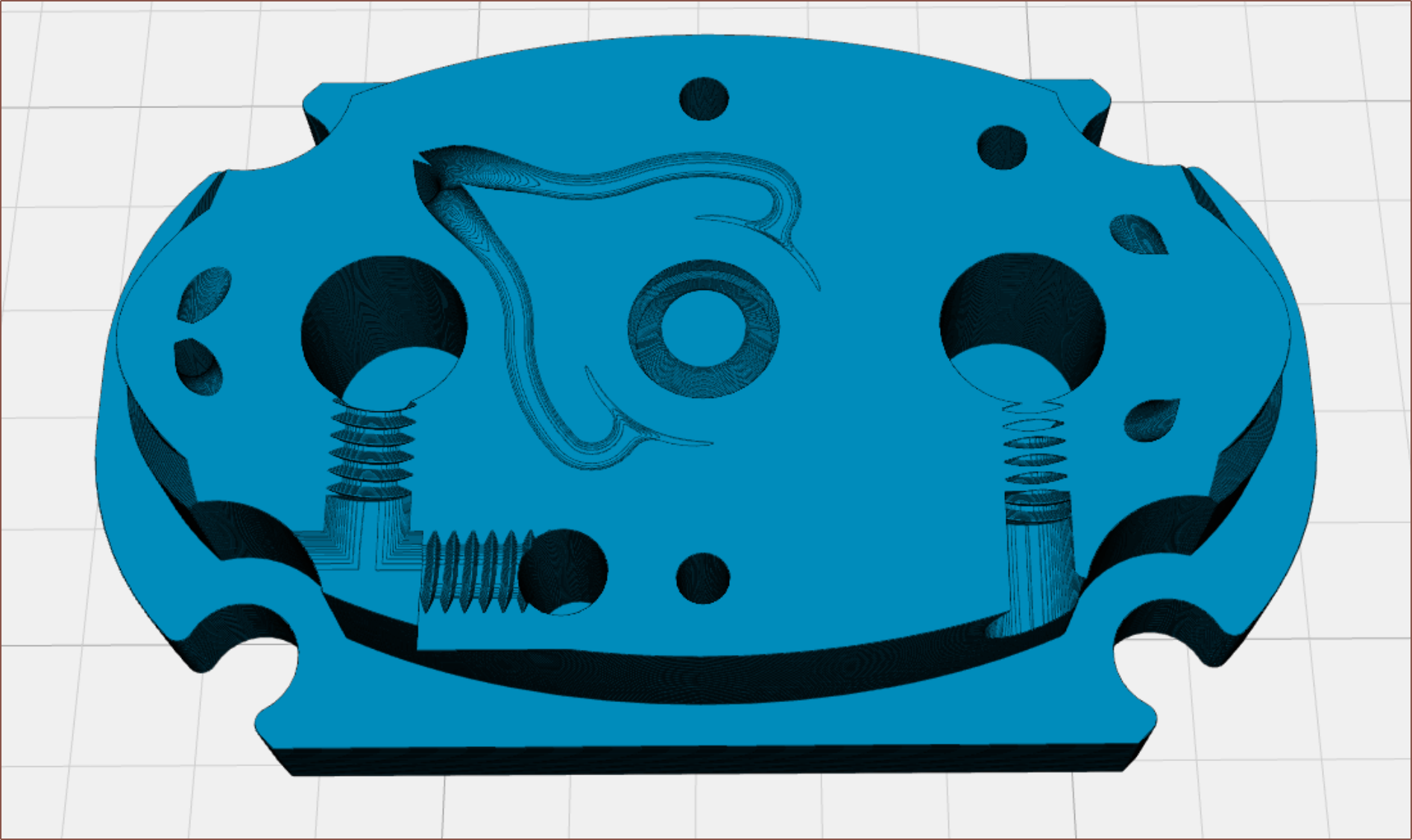
So I did the usual cross section analysis and found this issue of floating material:
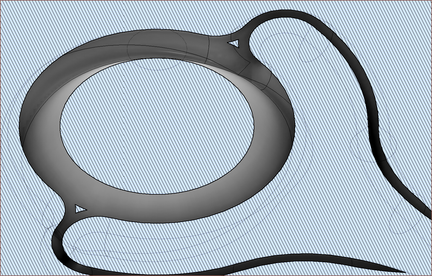
Fixing it was not straightforward, and I was getting geometry like this:
The solution was to remove the triangle on the left/right path profiles, and have a straight extrude, and then fillet the result:
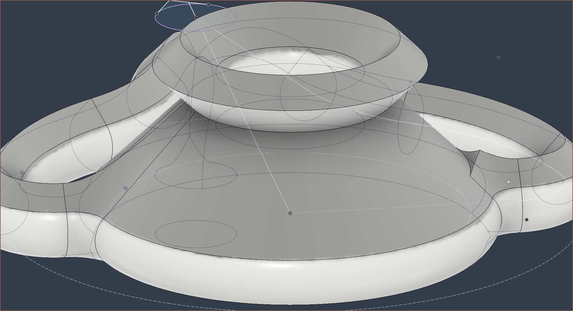
I was having issues with the fillet because the underside was bumpy, so I flattened it out with some Delete Faces magic:
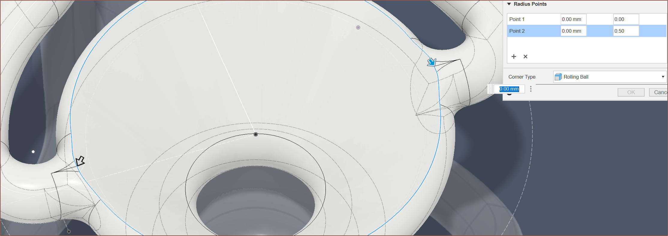
Lastly, I split the faces so that the variable fillet had nice points of 0.0, 0.25, 0.5, 0.75:
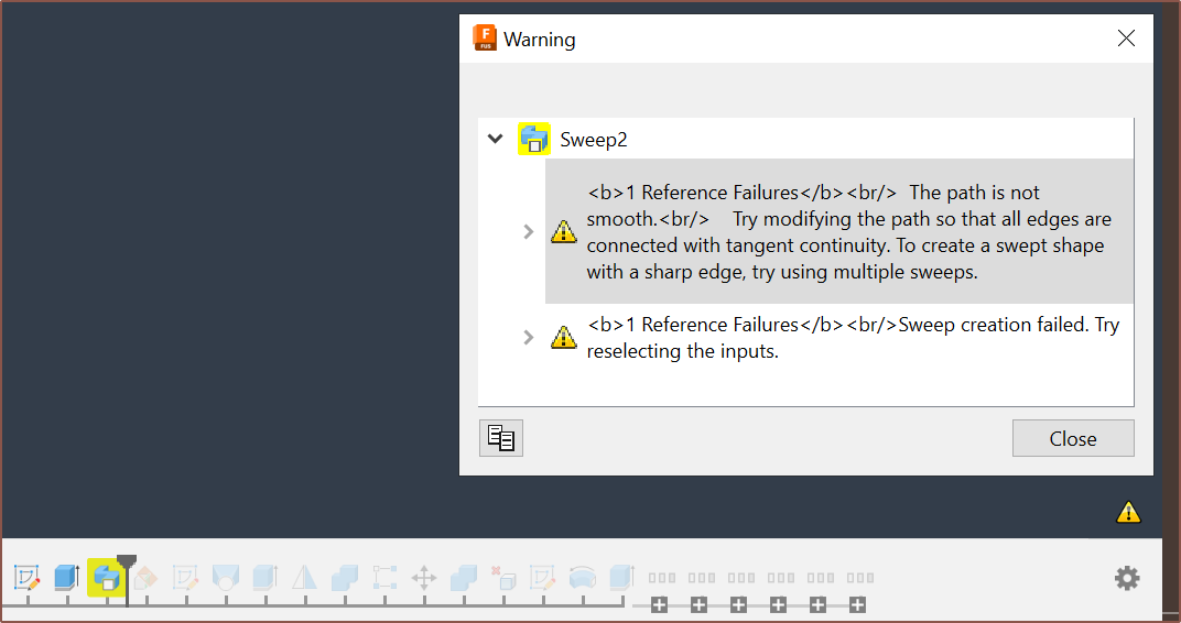
Throw in a few unexpected erros that resolved themselves when dimensions were tweaked by 0.1mm...
... and I got a satisfactory result that didn't violate minimum wall thickness, as seen below.
Analysis and quotation
So I did a more thorough cross section search this time, using both Fusion and Kiri:Moto. I took the exported .step and added in modelled M4 threads to represent what would happen after post processing.
Just look at that difference between R0 and the current R1 design:
The cross sections all looked like there was ample distance between walls (which I'd then confirm in Fusion):
I've sent in a quote and I'm currently waiting to hear back from the engineer before I press buy this time, but I've already gotten the pricing quote back:
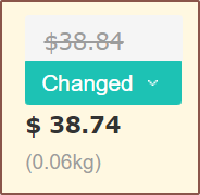
Yes! You see that, right? $38.74. For the first time ever, the actual quote is less than the auto-quote! Yes it's 10 cents, but this is amazing how I've essentially gotten the price down to PCBWay's single-quantity minimum of around 37-39 USD. I will mention though that Heinz has found that for a much smaller part, one can get 1pc for the same as 5pcs, thus $6/ea.
[20:20]
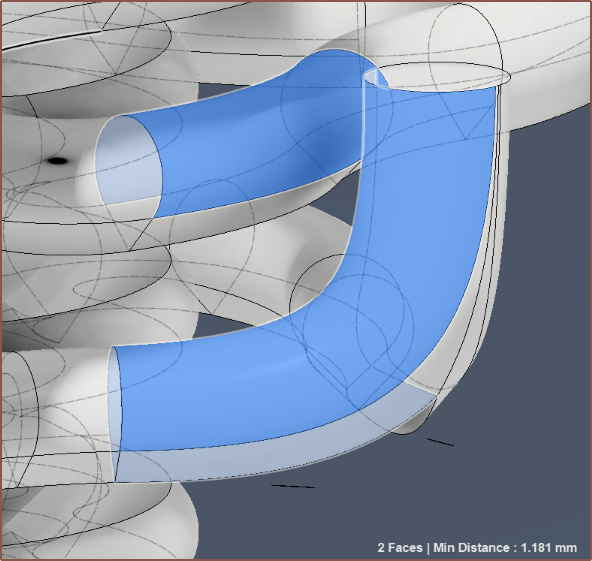
By quickly scrolling between the layers in Kiri:Moto, I was able to see that I could easily eliminate the slight minimum-wall violation I mentioned earlier (1.181 < 1.2) by just swapping the input locations of Ch5/6. This results in being able to use a normal arc instead of a conic curve, simplifying the sketch calculation for the Ch7/8 outer trim and resulting in a 0.5g reduction in total mass (the volume is now 191cm^3).
If you're wondering why I keep mentioning the total volume when the mass differences are negligible, it's because I'm having fun beating personal best, similar in principle to Trackmania where I feel 0.4 seconds improvements are solid gains.
[21:50]
I noticed that one small fillet didn't look correct. I went to investigate and yes it was an actual issue:
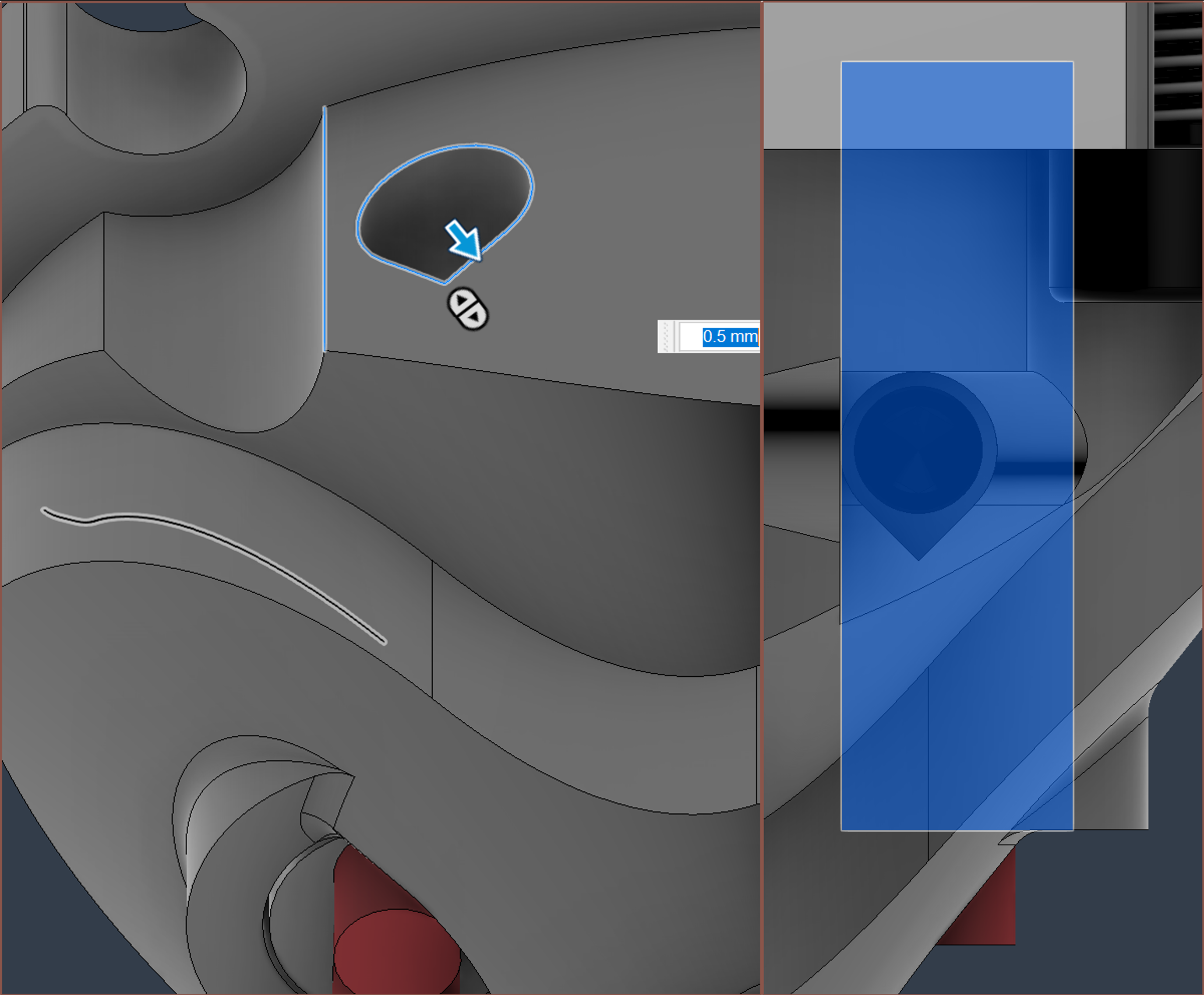
Turns out that the thermistor sketch broke a bit and was corrected. I've now gone into the FDM mode of Kiri:Moto to confirm that minimum wall thickness, at least in the XY-Plane, is ensured. I've used a 0.6mm nozzle size, which means that all walls should have at least 2 lines of thickness.
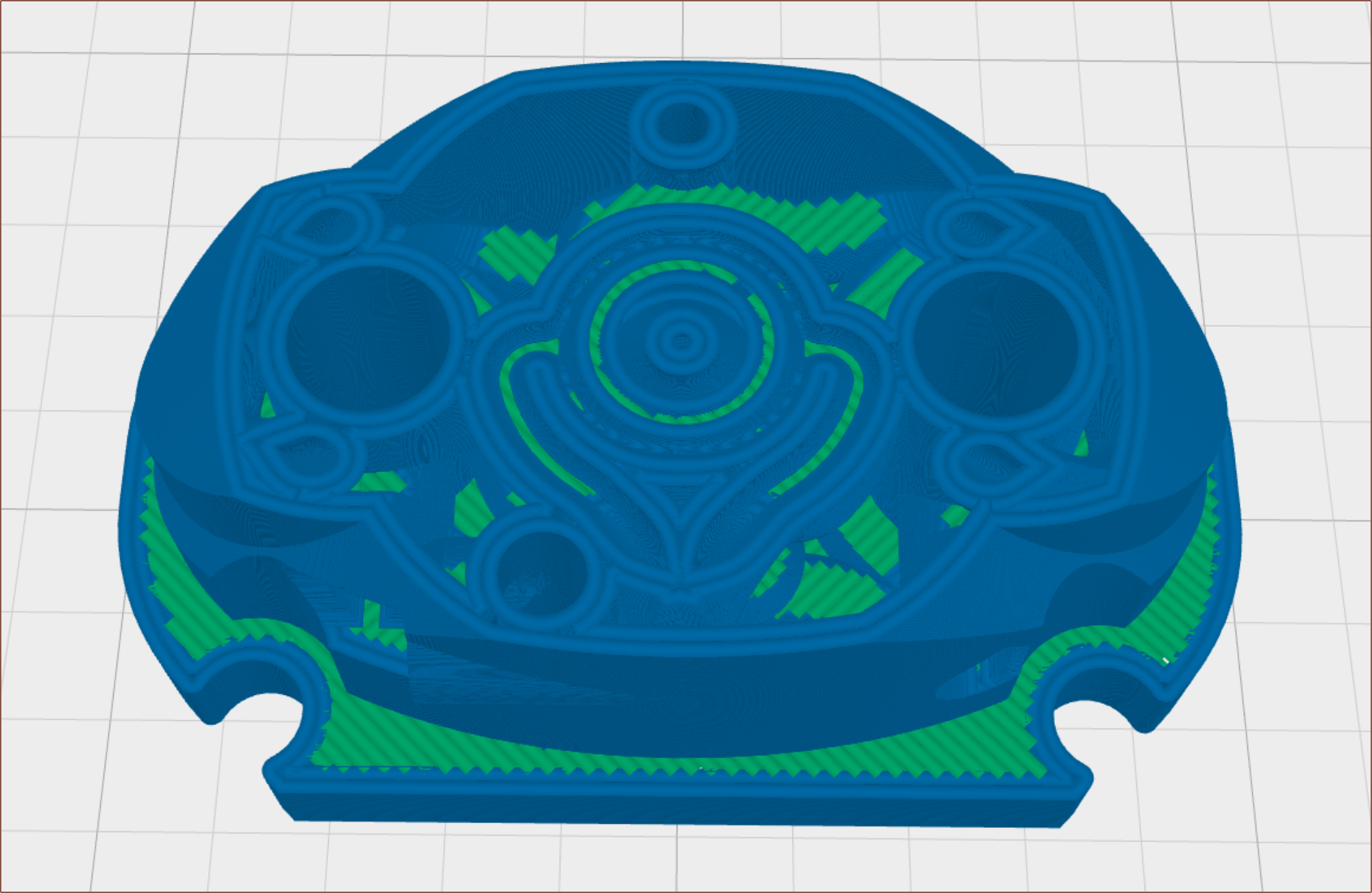
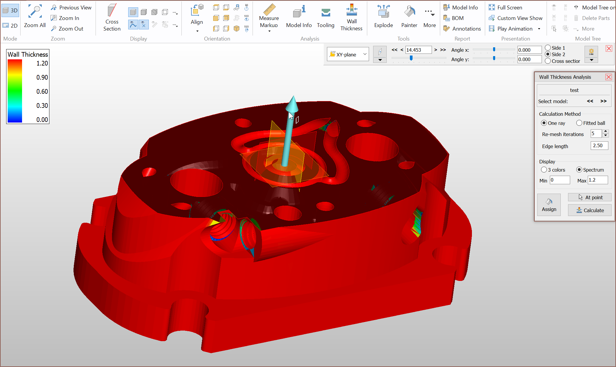
This still wasn't all that ideal, and so I set off to find a way to get a wall thickness analysis tool and found the free 3D-Tool viewer which can take in a .3mf and I can get both analyses for cross section and minimum wall!
[Apr 13]
I've combed though and I think all the issues with the CAD has finally evaporated off. I've removed the minimum wall violation where the grub screw was, and I've added some nice 6mm fillets that was mainly to try and address the furthermost grub hole but I believe is just what the design needed for this nice, flowy look.
Hopefully, this design is manufacturable. I have the confidence that, as long as the price is close to the autoquote, I'm getting 2pcs so that it's not instantly "game over" if Team Leak get's a 3-0 in this battle. I believe that the design is good enough that I would need concrete performance metrics before I tweak and change anything else.
[Apr 14]
I've realised that it's actually possible to set an internal coaxial spacing lower than 0.94, whcih will actually thicken the walls.
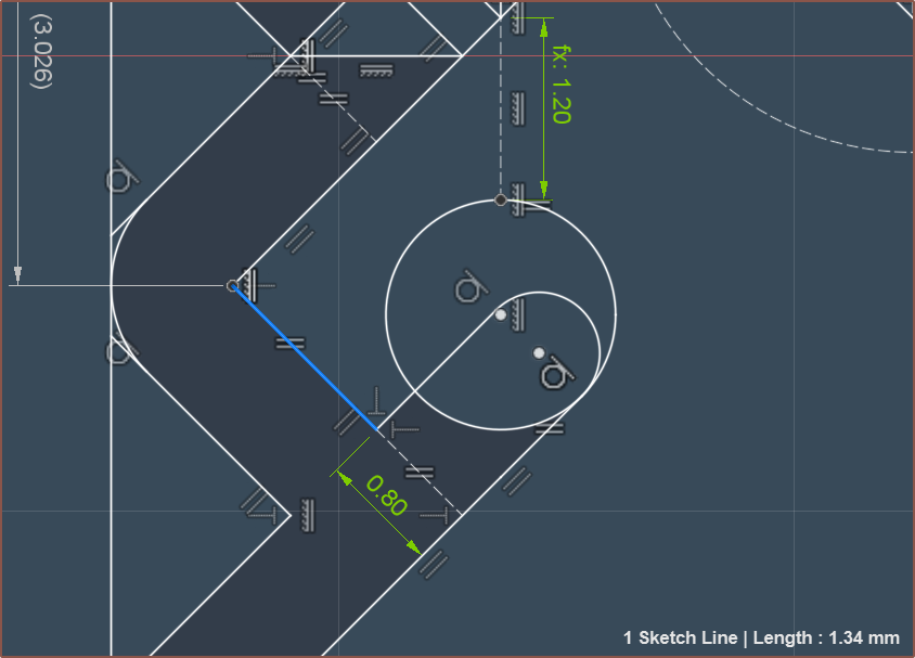 A reduction from 0.94 to 0.80mm (15%) decreases the hypothetical purge volume by about 30%. Remember though that this is all just raw-CAD numbers and the spacings between the walls are expected to be lower in manufacture. The worry is lower flow rates. I know 0.95mm spacing works so I'm just going to stick with the 0.94mm modelled.
Discussions
Become a Hackaday.io Member
Create an account to leave a comment. Already have an account? Log In.