Close
0%
0%

A+ Split Keyboard

Over 104+ Key Split Keyborad

Public Chat
Similar projects worth following
This project provides a split keyboard that supports all the keys of a typical full-array keyboard.


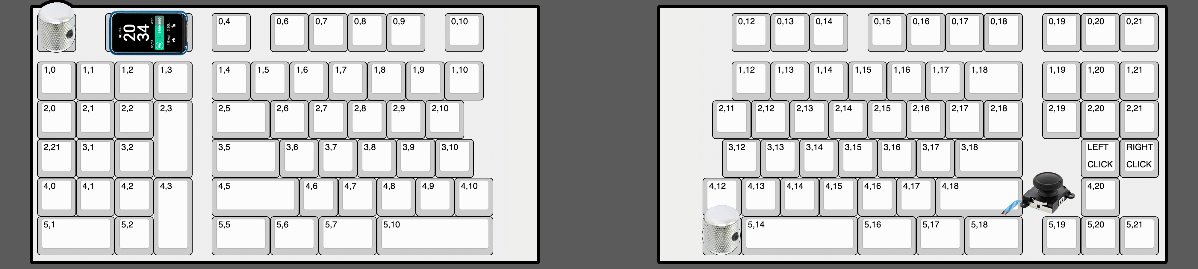
After an extensive search for a split mechanical keyboard that caters to Mac users and supports all key functions, I decided to take matters into my own hands and create one myself.

As I embarked on this DIY project, I needed to outline the specific requirements and incorporate some additional elements tailored to my workflow and preferences for added enjoyment


Core Requirements:


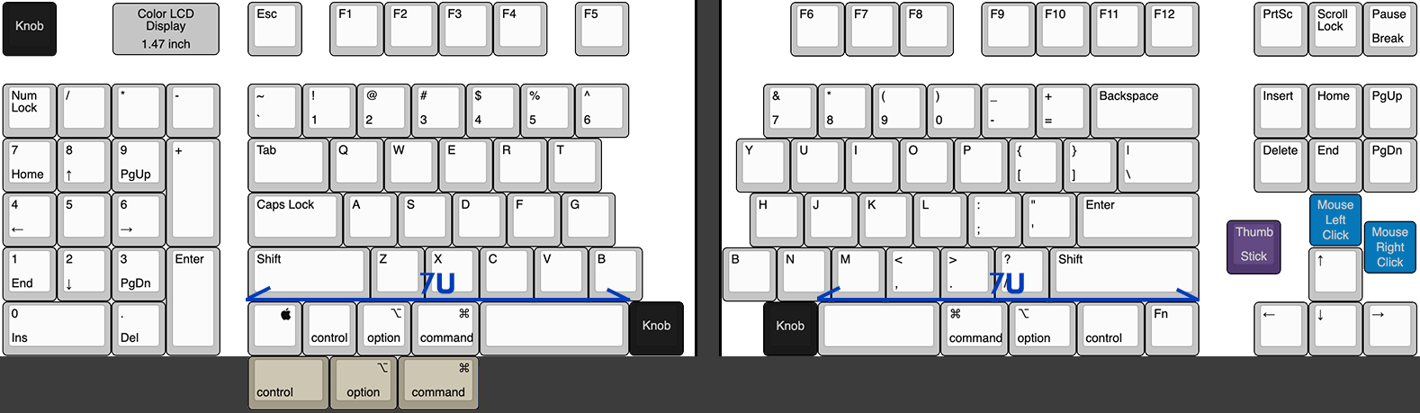
My initial quest for the perfect keyboard was guided by three primary criteria:

  • A user-friendly keyboard layout that avoids unconventional designs
  • Command key positioning that aligns with the Apple Magic Keyboard
  • Comprehensive key support, including function keys

Despite my efforts, I couldn't find a suitable keyboard, prompting me to start this project.

Supplementary Features:

  • KVM
    I typically work with two computers concurrently  a Mac and a Windows system  and rely on a software-based KVM (Synergy) to utilize a single keyboard and mouse across both machines. However, this setup often encounters issues, such as when the host computer is powered off, requires updates, or needs BIOS access. These exceptions force me to repeatedly switch ports physically.

    To address this inconvenience, I decided to integrate a USB port for basic HID relay functionality and multiple USB ports for built-in KVM capabilities.
  • JoyStick & Mouse Click & Scrolling Knob
    Most of the time you will be alternating between keyboard and mouse while working. Most of the time you can get around this by using shortcuts, but you don't want to move your hands away from the keyboard unless you absolutely have to. We'll make it possible to do all the basic mouse functions within the keyboard.  

    We'll use the knobs to support wheel (X-axis, Y-axis) functionality, mouse movement via the Joystick module, and separate buttons for left and right mouse clicks.

Fun Features:

  • Full RGB LED
  • Fancy Color Display (1.47 inch)
  • Hotwswap Socket


Hardware Parts (Mk.1)

  • Raspberry Pi Pico
  • SK6812MINI-E (RGB LED)
  • WaveShare 1.47inch LCD Module

  • More Debugging, Better Layouts

    Ironpark06/11/2023 at 14:05 0 comments

    After exploring the prototype board for a while, I came across a few hardware errors. This prompted me to incorporate debugging ports and make some adjustments to the layout for the case design. While fine-tuning the board design, I also took the opportunity to make some tweaks to the keyboard layout.

    I modified the keyboard layout for more keycap compatibility, easier PCB routing, and some usability.

    - Placed the knobs on both sides for usability.
    - Modified the key placement to provide additional space for the joystick position.
    - Used a more common and readily available keycap size for the spacebar.
    - Applied multilayout to some columns (more keycap compatibility)

  • USB-C mod for pico based pcb project

    Ironpark06/08/2023 at 12:45 3 comments

    In 2021, the Raspberry Pi Foundation released the Pico, a small and powerful microcontroller board that offers high performance and flexibility. However, the board's use of a micro-B USB port is considered a drawback. This is especially true considering that the Raspberry Pi 4, released in 2019, uses a USB-C port for power delivery.

    Since then, various companies and individuals have released many boards based on the RP2040, some with USB-C ports, others without USB ports and with exposed D+/D- pins for customization (like RP2040 Stamp). However, most of these projects are either hard to find in low quantities, expensive, or require international shipping, whereas the original Pico board is in stock in most countries and can be obtained cheaply and quickly.

    So what if you could just replace the USB ports on the original PICO board with the type you want?

    Below shows the approach that one Reddit user took to convert an original PICO board to type-c, using the TP1,TP2,TP3 pins on the back of the board and a USB-C breakout board.
    https://www.reddit.com/r/raspberry_pi/comments/m8p2ed/usb_type_c_mod_for_pico/

    We decided that this was something we could use in our PCB design, and below is the result on our prototype board.

  • Diode Placement with Python and KICAD 7.0

    Ironpark05/10/2023 at 17:16 3 comments

    I found it necessary to adjust the position and orientation of the diodes across the board to make the routing effective. Fortunately, KICAD supports a Python console to automate this repetitive task, and since I had previously used KICAD to create scripts to automate part placement, I used my previous code to create a diode placement script.

    KICAD does not guarantee that the PYTHON API will remain compatible between versions.
    The script below only works with KICAD 7.x.
    import pcbnew
    from pcbnew import *
    
    def SetPosition(footprint,x,y):
        footprint.SetPosition(pcbnew.VECTOR2I(pcbnew.wxPoint(x,y)))
    
    def DiodeRePosition(relX,relY,angle):
        footprints = pcbnew.GetBoard().GetFootprints()
        diodeToKeyPosition = {}
        for f in footprints:
            ref = f.GetReference()
            pos = f.GetPosition()
            if "K_" in ref:
                keyNum = int(ref.split("_")[1])
                diodeRef = "D_{}".format(keyNum+1)
                diodeToKeyPosition[diodeRef] = [pos.getWxPoint().x,pos.getWxPoint().y]
                print(diodeRef,diodeToKeyPosition[diodeRef])
        for f in footprints:
            ref = f.GetReference()
            if "D_1" == ref:
                continue
            if "D_" in ref:
                [x,y] = diodeToKeyPosition[ref]
                f.SetOrientation(EDA_ANGLE(angle, DEGREES_T))
                SetPosition(f,x + FromMM(relX),y - FromMM(relY))
        pcbnew.Refresh()
    
    DiodeRePosition(5,8.8,330)

     
      To create the above script, I referenced the official documentation and forum posts below

  • LED, LCD and more ..

    Ironpark04/29/2023 at 19:55 0 comments

    Time to design the PCB.

    After completing the basic placement and simple routing for the LEDs, To mount the LCD module, I made a footprint with four 2M size hole mounts and a square hole for cable exit based on the specifications listed on the waveshare website.

  • Started the PCB design for the left keyboard.

    Ironpark04/28/2023 at 20:17 0 comments

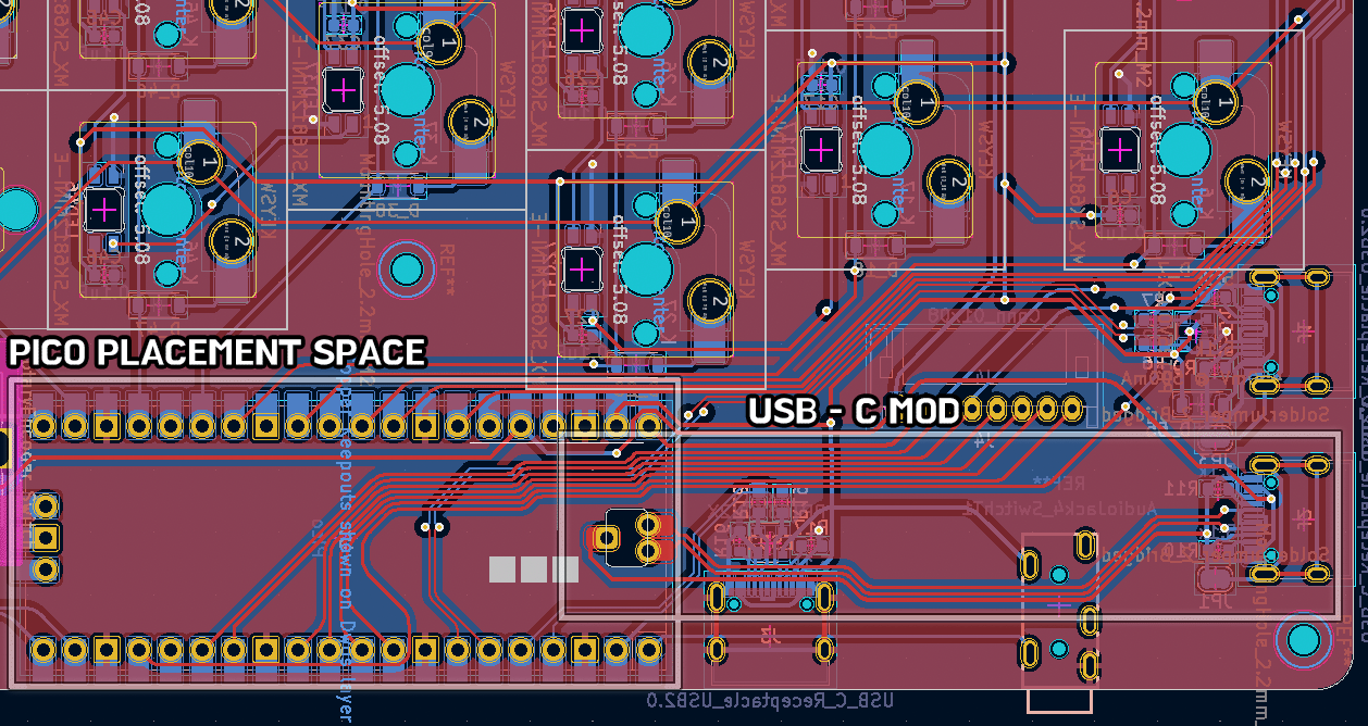
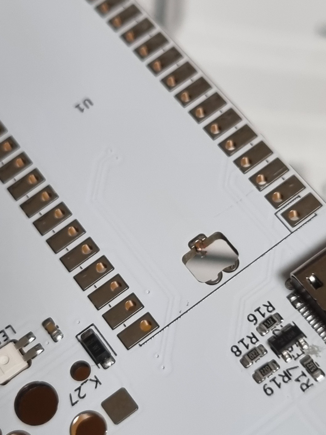
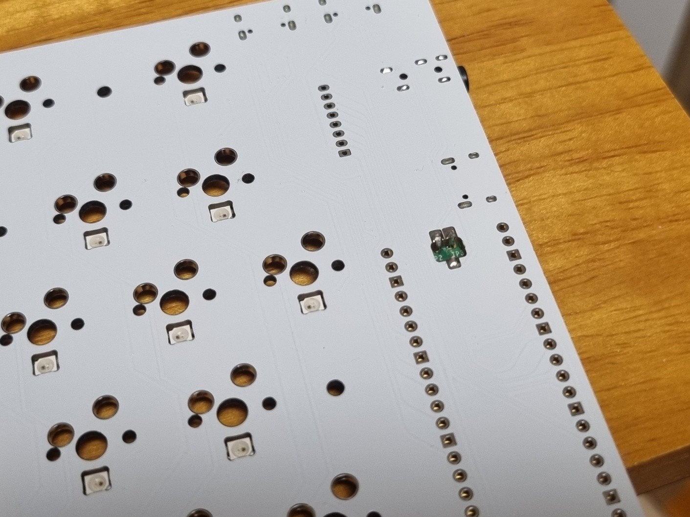
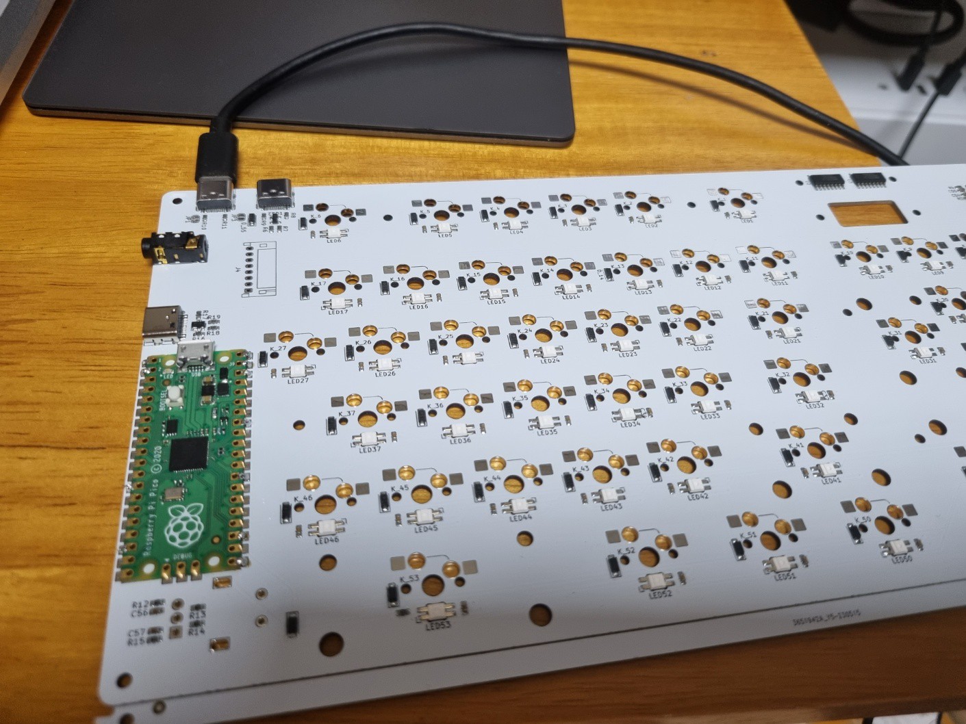
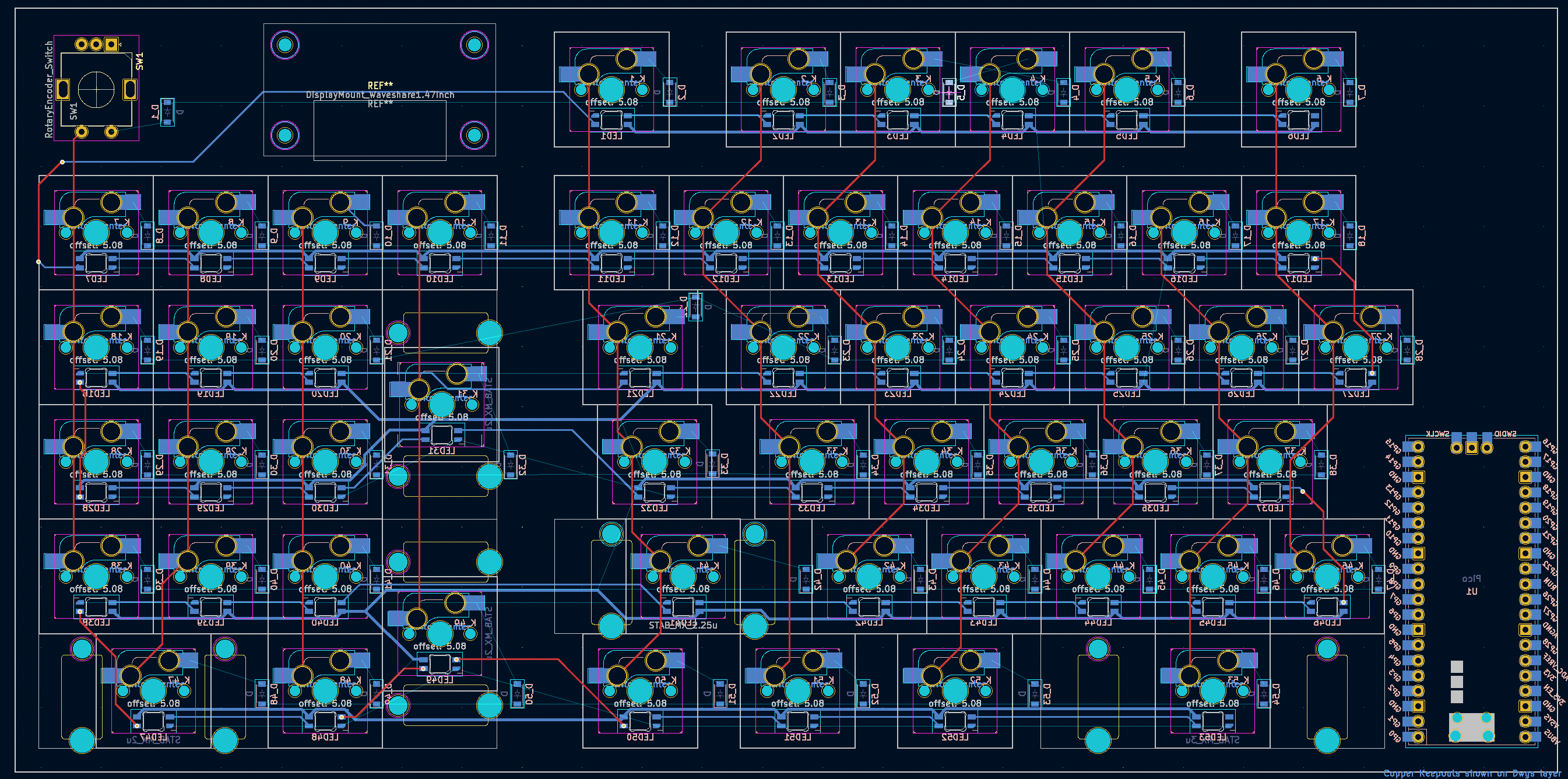
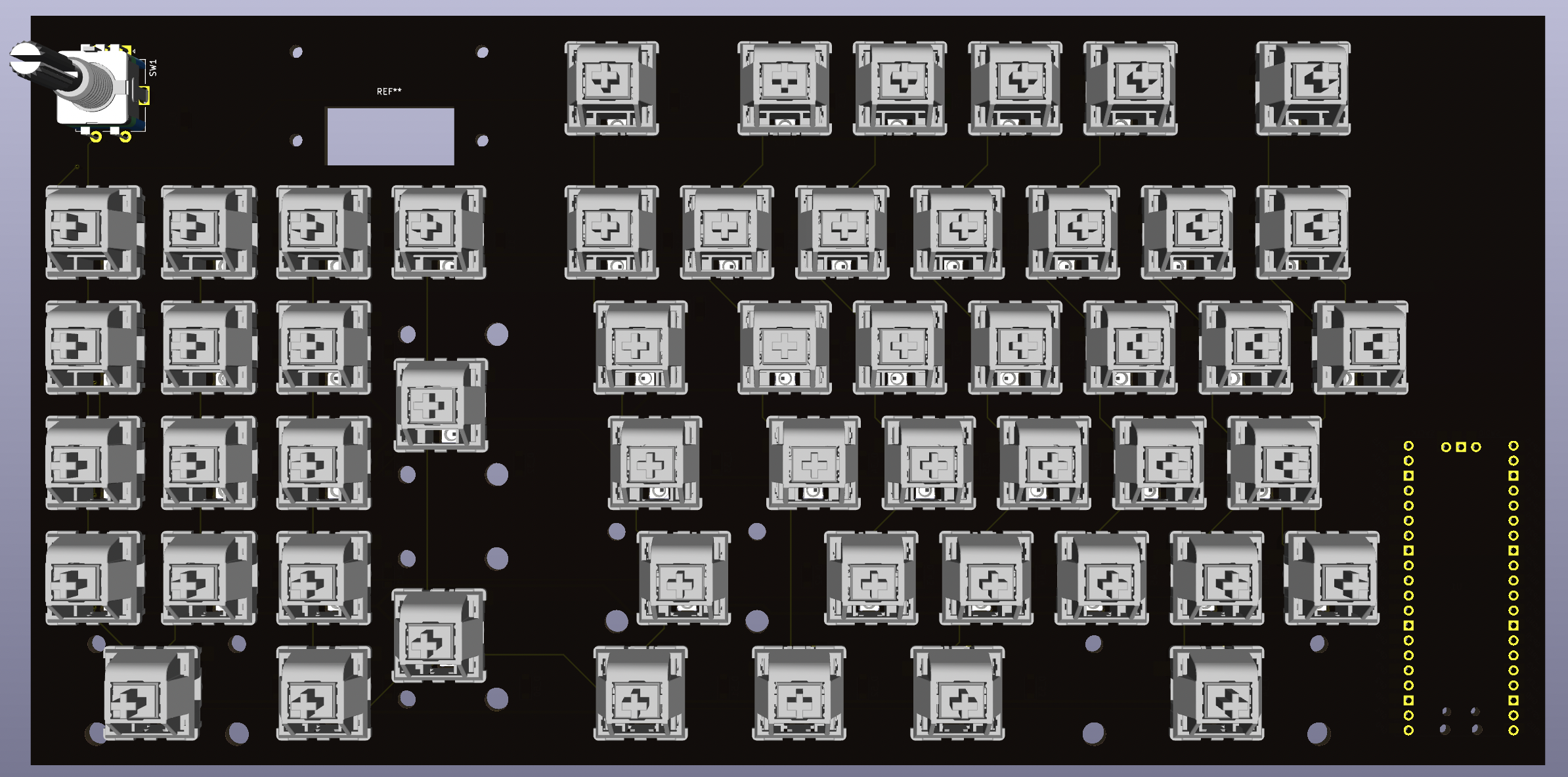
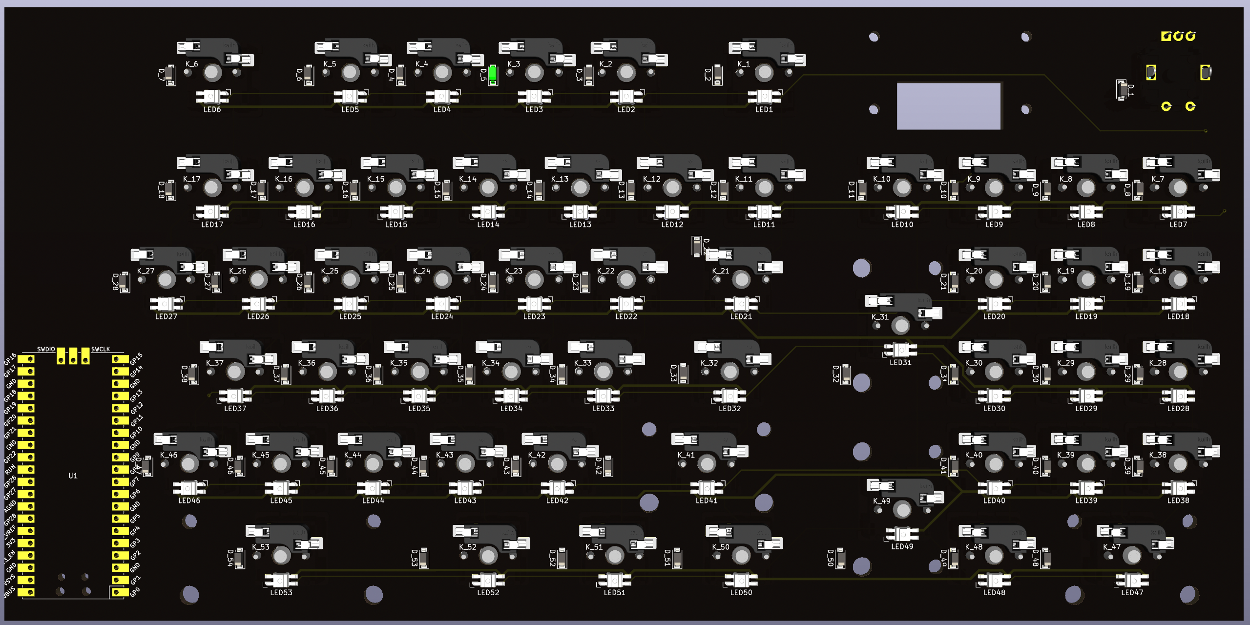
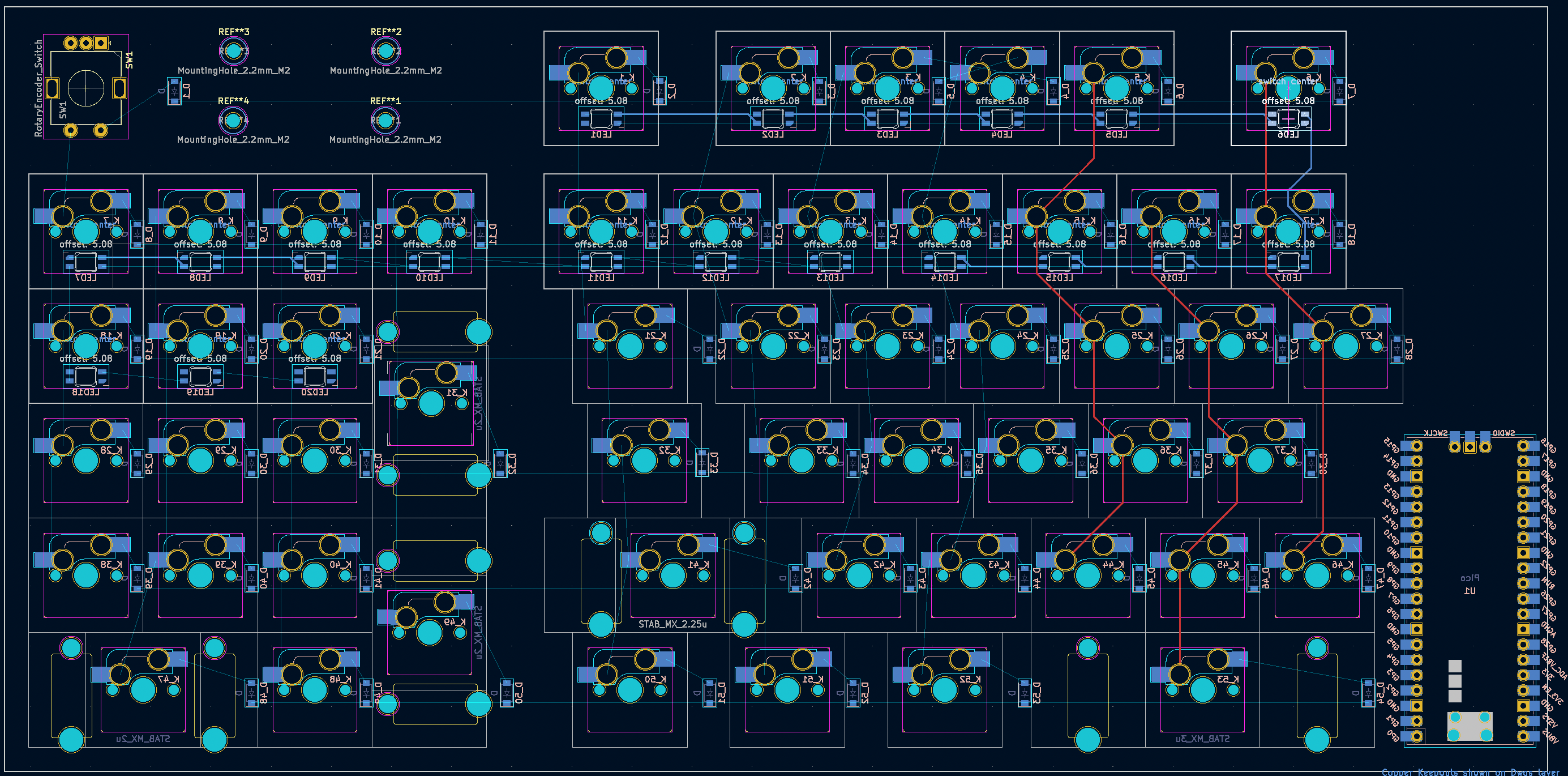
    I'm placing the main controller the Pico board, the rotary encoder, the display mount-hole hot-swap socket and stabilizer, and the LEDs.
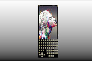
View all 5 project logs

Enjoy this project?

Share

Discussions

Similar Projects

Does this project spark your interest?

Become a member to follow this project and never miss any updates