Why, What and How
Contrary to what they may seem on the outside, non-verbal autistic individuals are intellectually intact. They may know exactly what they want to say, but may be unable to say it. They may know how to play a game, but sit motionless, or simply rock back and forth. As much as someone with autism might want to, it may seem impossible to turn a thought in his head into speech from his lips, or to convince his/her hand to pick up a pencil—in other words, bridging the gap between intention and action can be an impossible task.
Some research shows that providing gentle physical cues, or “proprioceptive feedback,” can help individuals with autism complete motor movements. A tap on the shoulder or elbow is often enough to help someone translate an intent to move into physical motion.
Soma Mukhopadhyay created a method called RPM to open a window into their minds where the teacher or facilitator learns how to access the open learning channels (auditory, visual, tactile and kinesthetic) of the student and adapts the sessions accordingly. This allows them to communicate, slowly and painstakingly, by pointing at a letterboard to spell their thoughts as well as to expose them to information and interaction that they would otherwise never have.
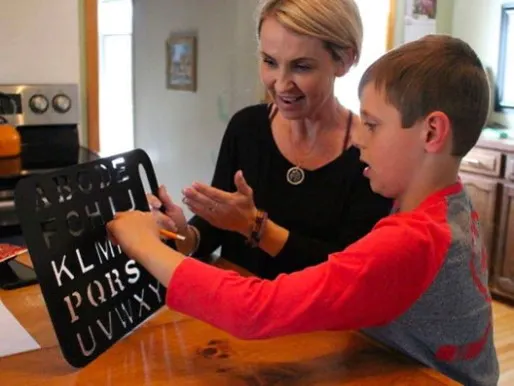
Eventually, a few students can move to something like an iPad (LA Times: In the ‘silent prison’ of autism, Ido Kedar speaks out). The transition is not easy nor straightforward. There are a lot of sensory variables involved. Practice, patience and consistency are only a small portion of what's required.
To assist in that transition, I built this letterboard that acts as a Bluetooth keyboard, sending its output to an iOS or Android tablet which provides spoken feedback of each character and word through its Text-To-Speech capabilities, also providing visual feedback on the letterboard thru LEDs on each letter and a piezo for clicking sounds (and some Easter Eggs we'll cover later).
The hope is that, by adding visual and audio feedback to its shape and form, each letter acquires a distinct sensory fingerprint that may create stronger bonds to bridge the gap between intention and action.
It would have been orders of magnitude easier to create a simple App on iOS/Android (and there are many commercially available apps for assistive communication), but some autistic individuals perceive the light emitted by a screen as sensory noise, and others associate the screen of a tablet to game time (i.e. YouTube, games, etc.), disrupting their efforts at purposeful communication.
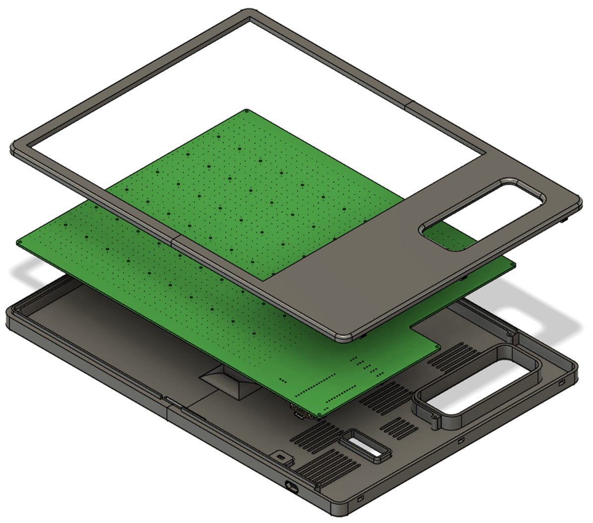
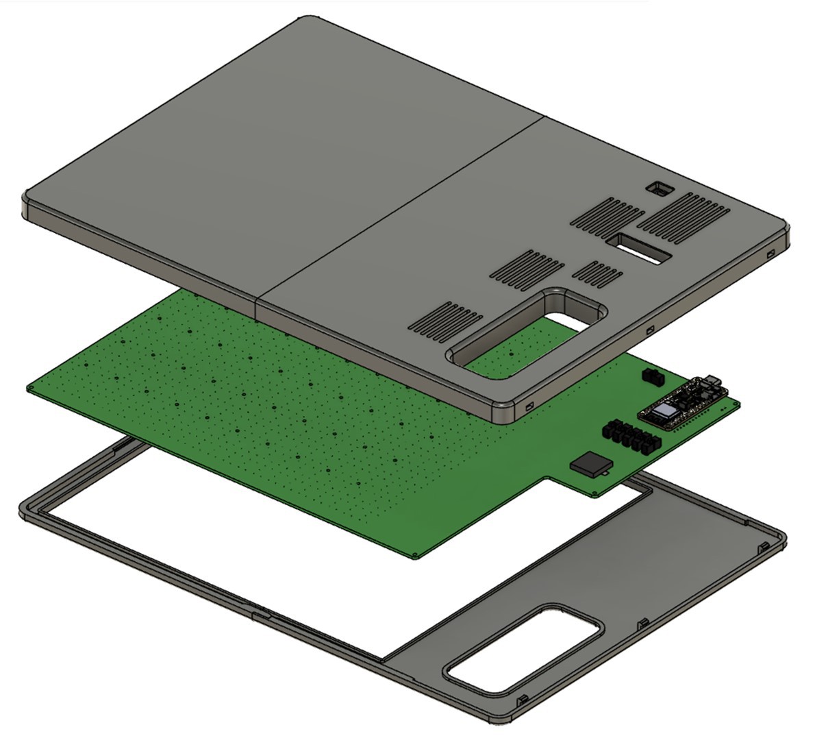
Elements in the Letterboard
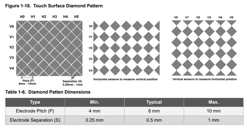
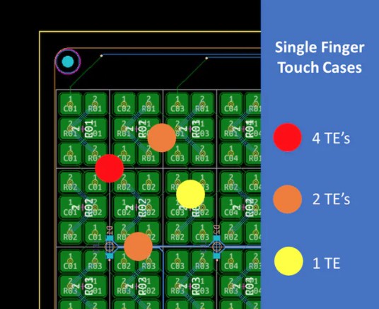
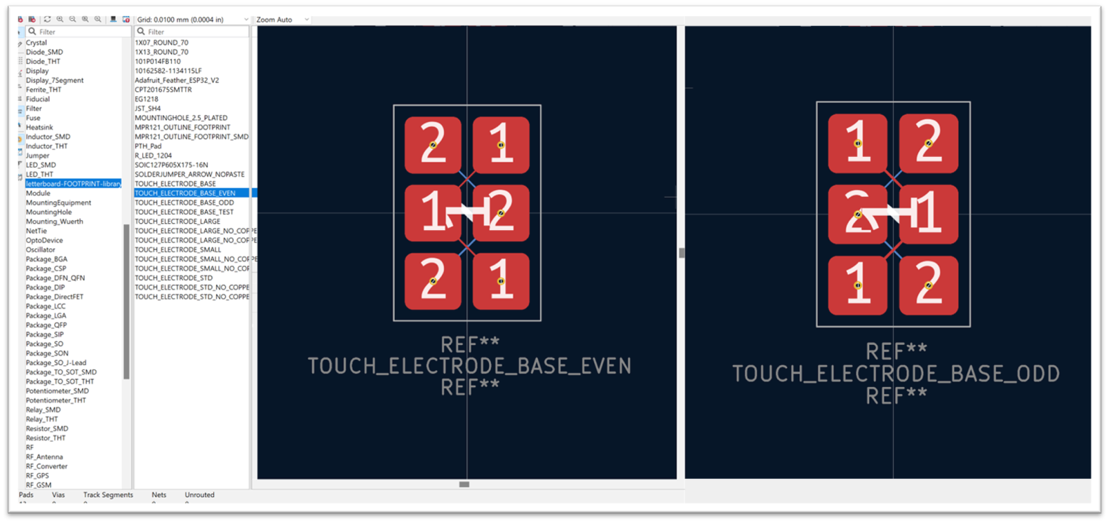
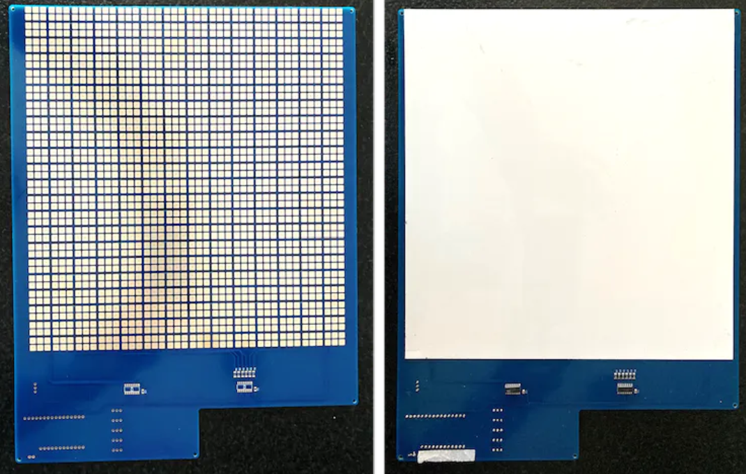
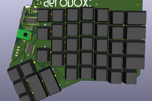
The letterboard consists of a 22x14 matrix of “Touch Electrodes” (TE). Each “TE” in turn, consists of a 2x3 matrix of copper pads. The pads are small enough so that a finger will touch at least 2 of the copper pads, providing the row and column that allow for its usage as a 2D touchpad (albeit with a 22x14 “pixel” resolution. Since this is only for letters, this is fine).
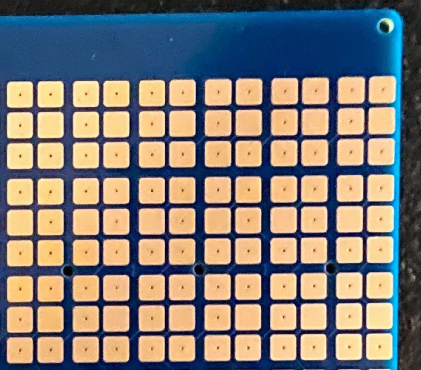
Each row and column of the TE’s connect to one channel of the three 12-Key Capacitive Touch Sensor Breakouts (Adafruit MPR121) for a total of 36 channels (22 columns + 14 rows = 36 channels). These 3 breakout boards use I2C to connect to the MCU and each has a distinct I2C address. The breakout boards are added to the PCB using SMD header pins (datasheet)
The MCU is an ESP32 (Adafruit ESP32 Feather). Because the MCU’s USB port will also serve as the letterboard’s battery charger port, it is added to the PCB using through-hole pins (to create a solid union that can withstand the multiple connect/disconnects of a USB charger).
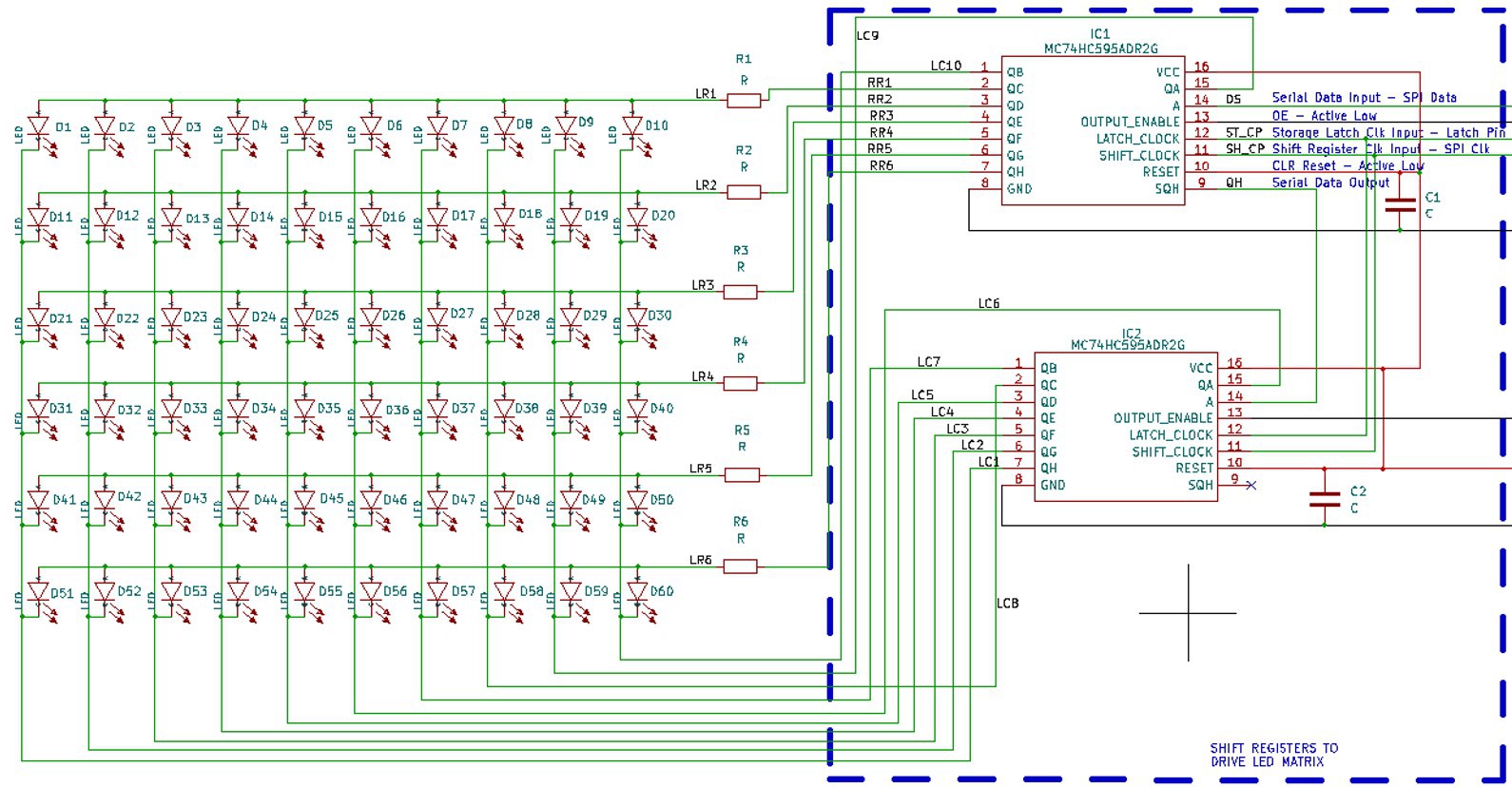
The letterboard also has a 10x6 LED matrix interspersed in the TE matrix. The LEDs are controlled by two 74HC595 Shift Registers...
Read more »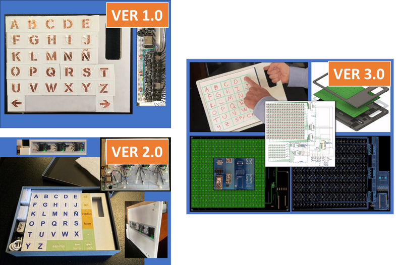


 Simon Merrett
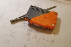
 Christian
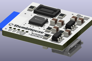
 Matias N.
 Stephen Harrison