 mit41301
INTRODUCTION:
In the analog signal Amplitude, Frequency and Phase are few considerable parameters. There are modulation and demodulation schemes available to achieve transmission and reception of the message between source and destination. There are ASK, FSK and PSK modulation technique available to choose. Each scheme will have it's own pros and cons.
We will try to build a FSK type modulator and demodulator.
FSK MODULATOR:
Basically we need to change the frequency of logic symbols '1' and '0' so that the receiver will understand what the transmitter is talking about. There are many way to achive the task. In the receiver end we need to identify the logic level from the incoming frequency. Mostly we adopt PLL based receiver.
Lets forget about the theory and we will do it in simple and practical way! Let's start!!
IMPLEMENTATION:
POWER SUPPLY:
We will operate transmitter and receiver with 3 V DC power supply. So we need two power supply. One for Tx and another one for receiver.
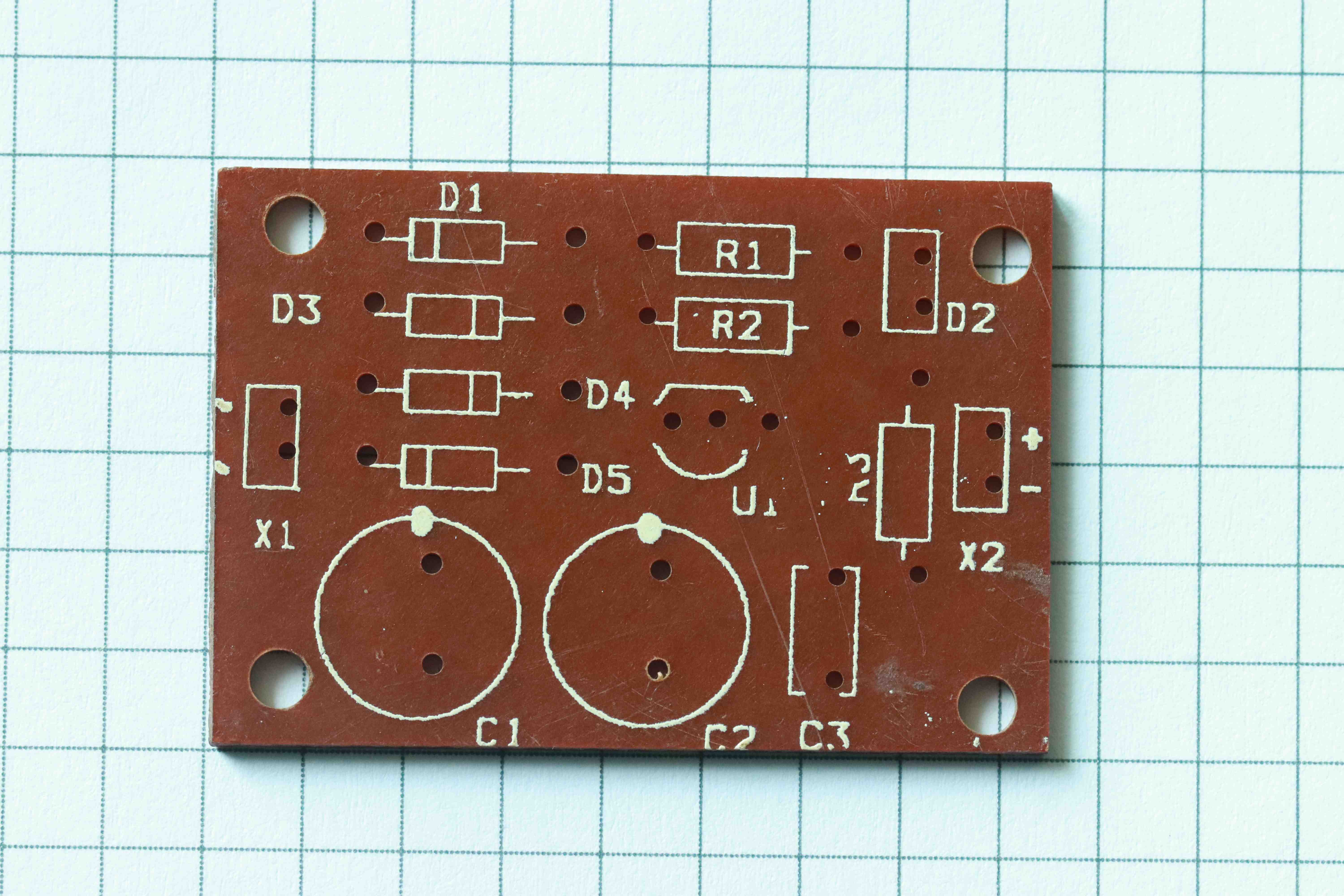
We will design a simple linear power supply using LM317 adjustable regulator. The AC input from transformer can be fed into X1 and the 3V output available at X2. We will be using U1 (LM317) in TO-92 case. Resistor R1 and R2 are used to program the output voltage. We will be using 470 ohms and 330 ohms.
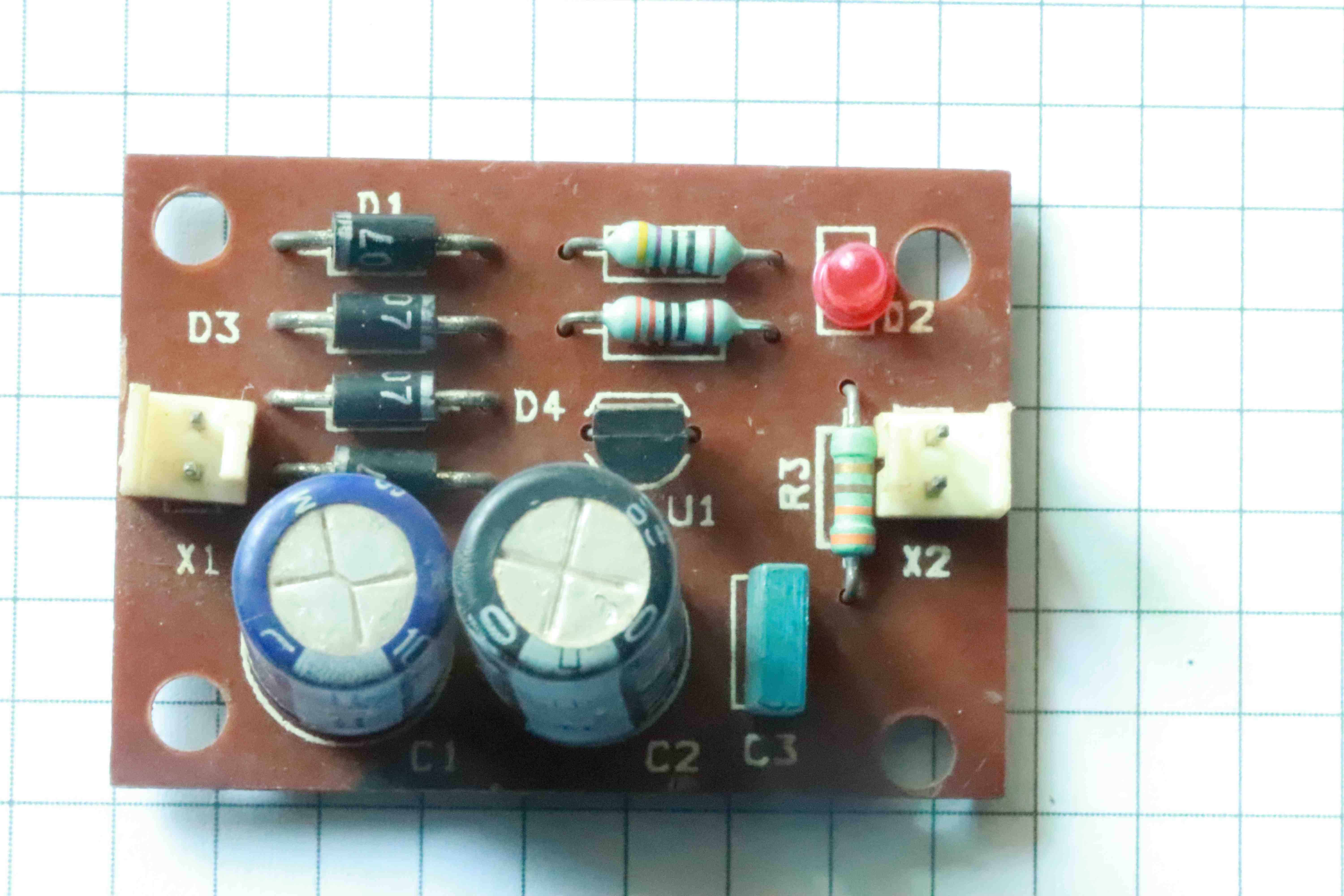
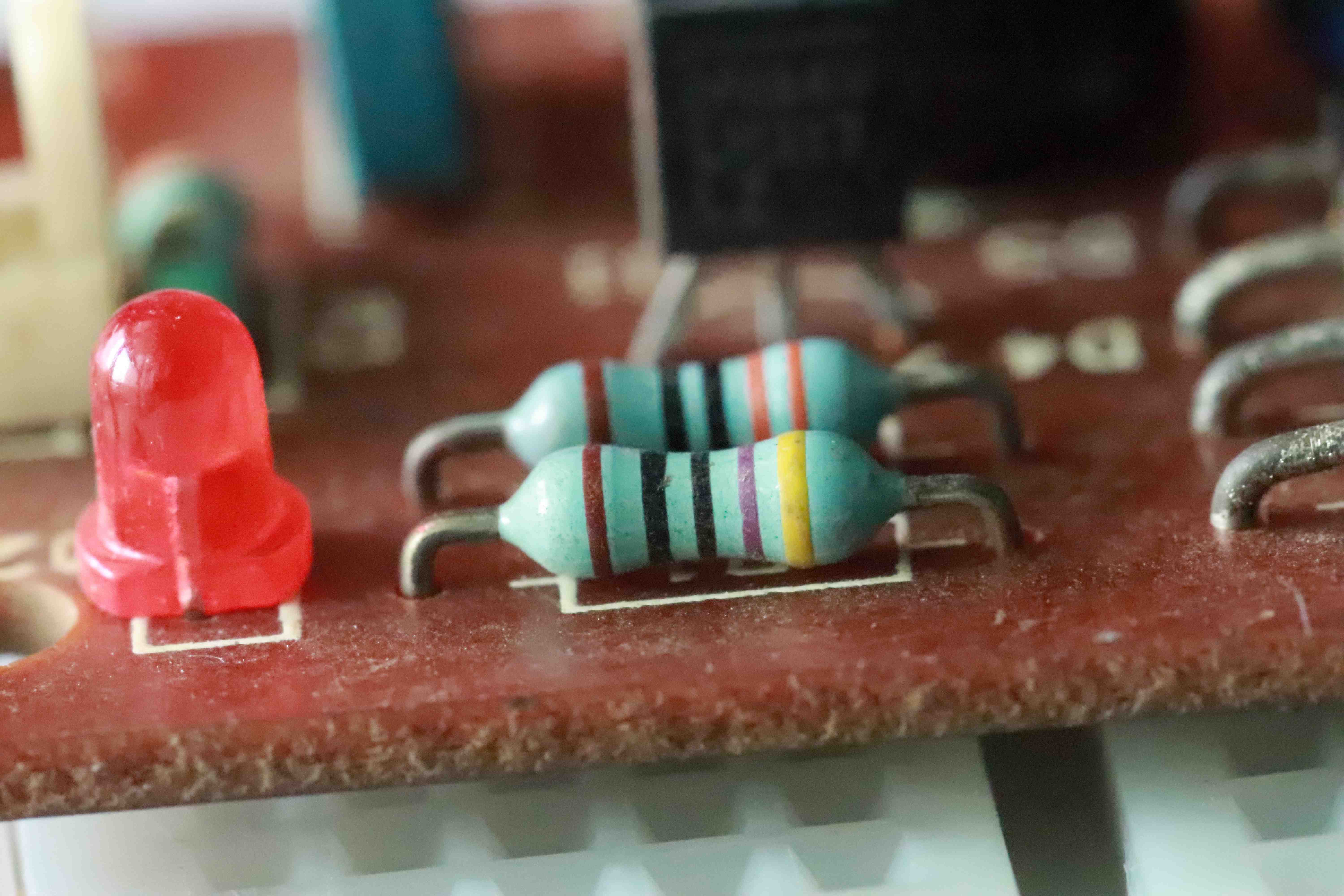
Resistor R3 and D2 are used for power ON indication.
Vout = 1.25(1+(470/330)
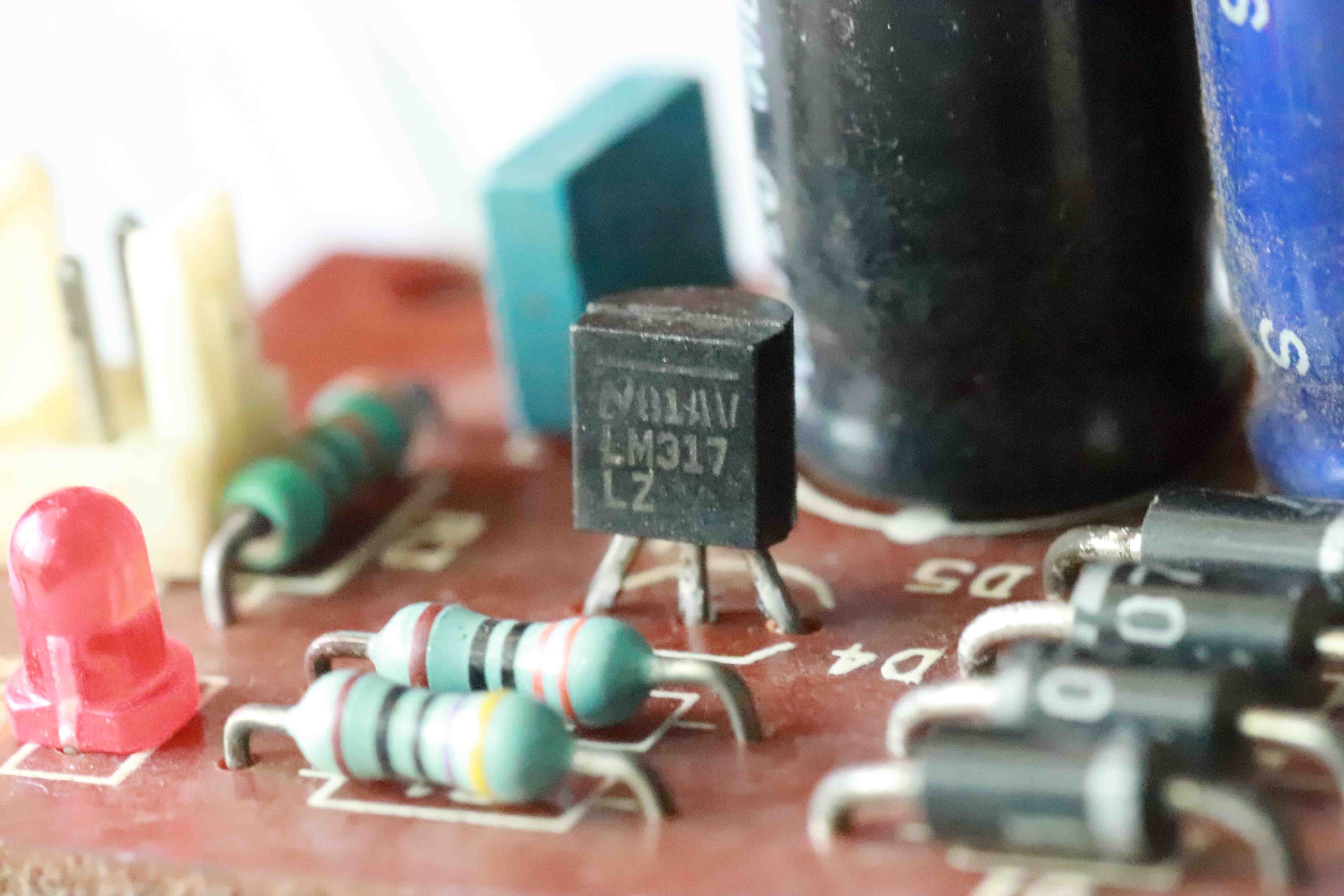
Adjustable voltage regulator LM317 in TO-92 case.
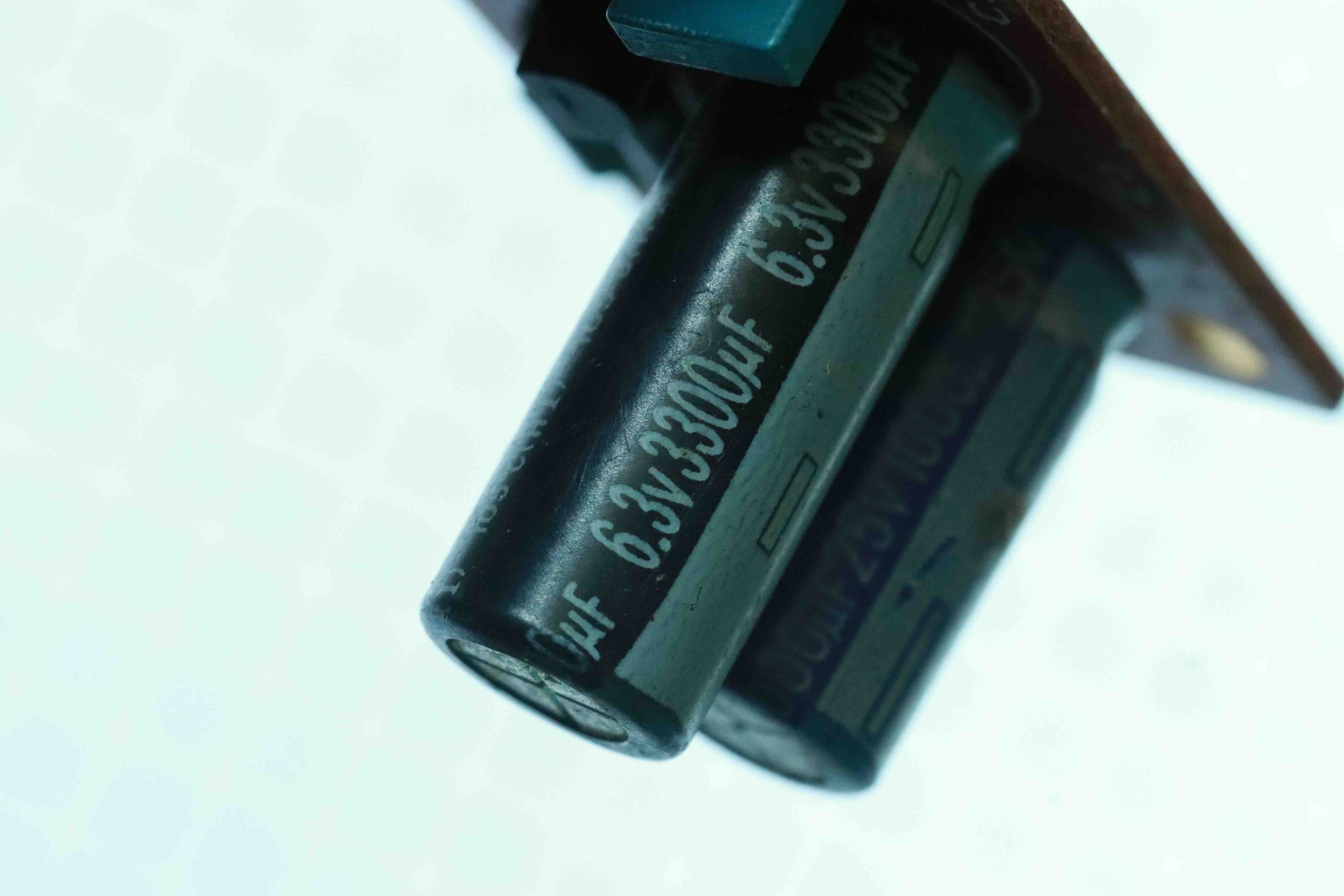
The input and output bulk capacitors for the regulator.
TRANSMITTER:
We will be using any RF generator with very limited output power so that our transmitter and receiver will work for say around 10 meter distance only.
We can use any RF oscillator capable of generating 76~108MHz. The advantage is easy for testing our transmitter with a standard FM radio receiver with frequency dial or digital frequency display.
We will go will a simple colpitts oscillator for our FM transmitter.
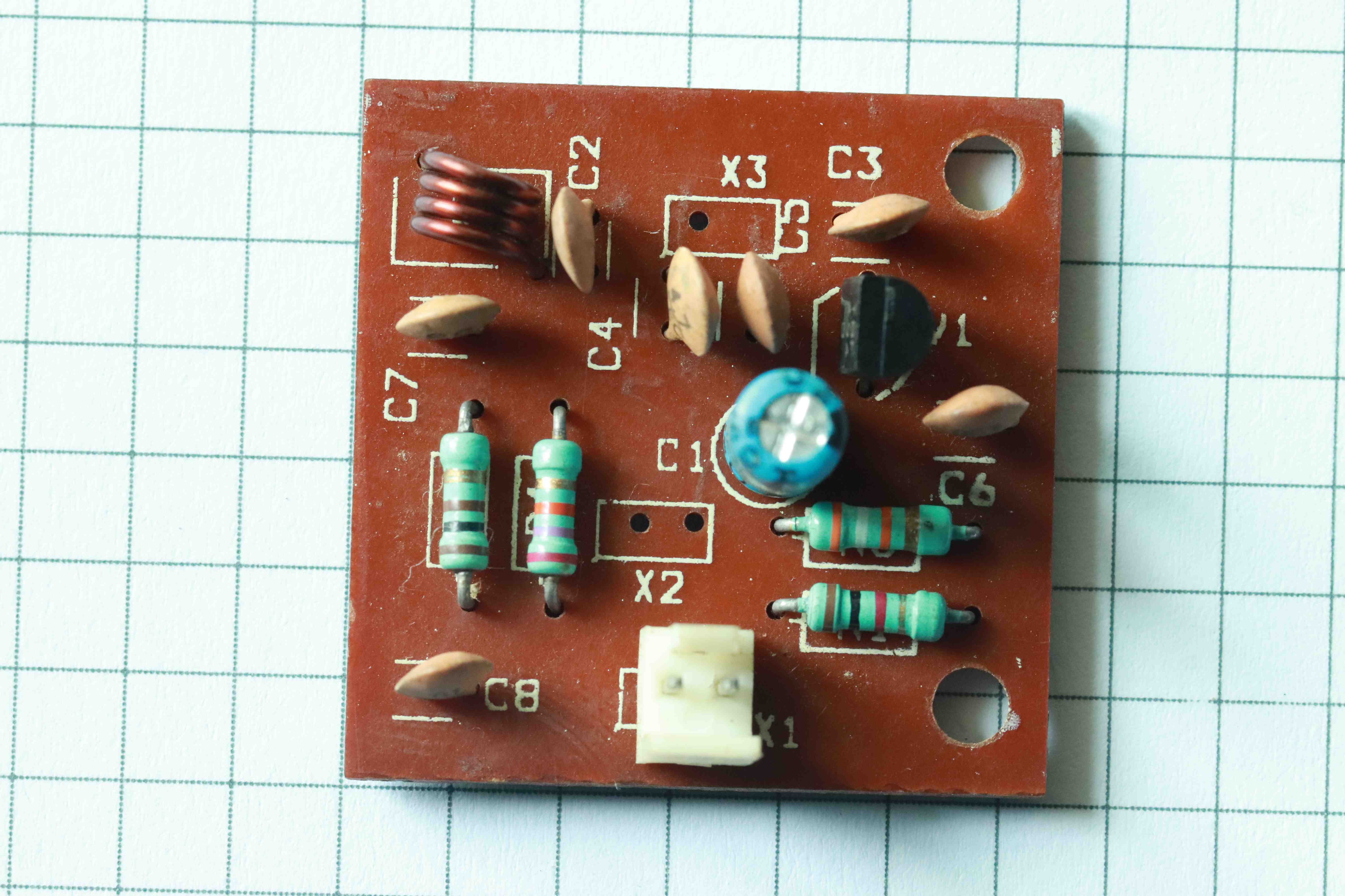
Now our transmitter is assembled and ready for testing.
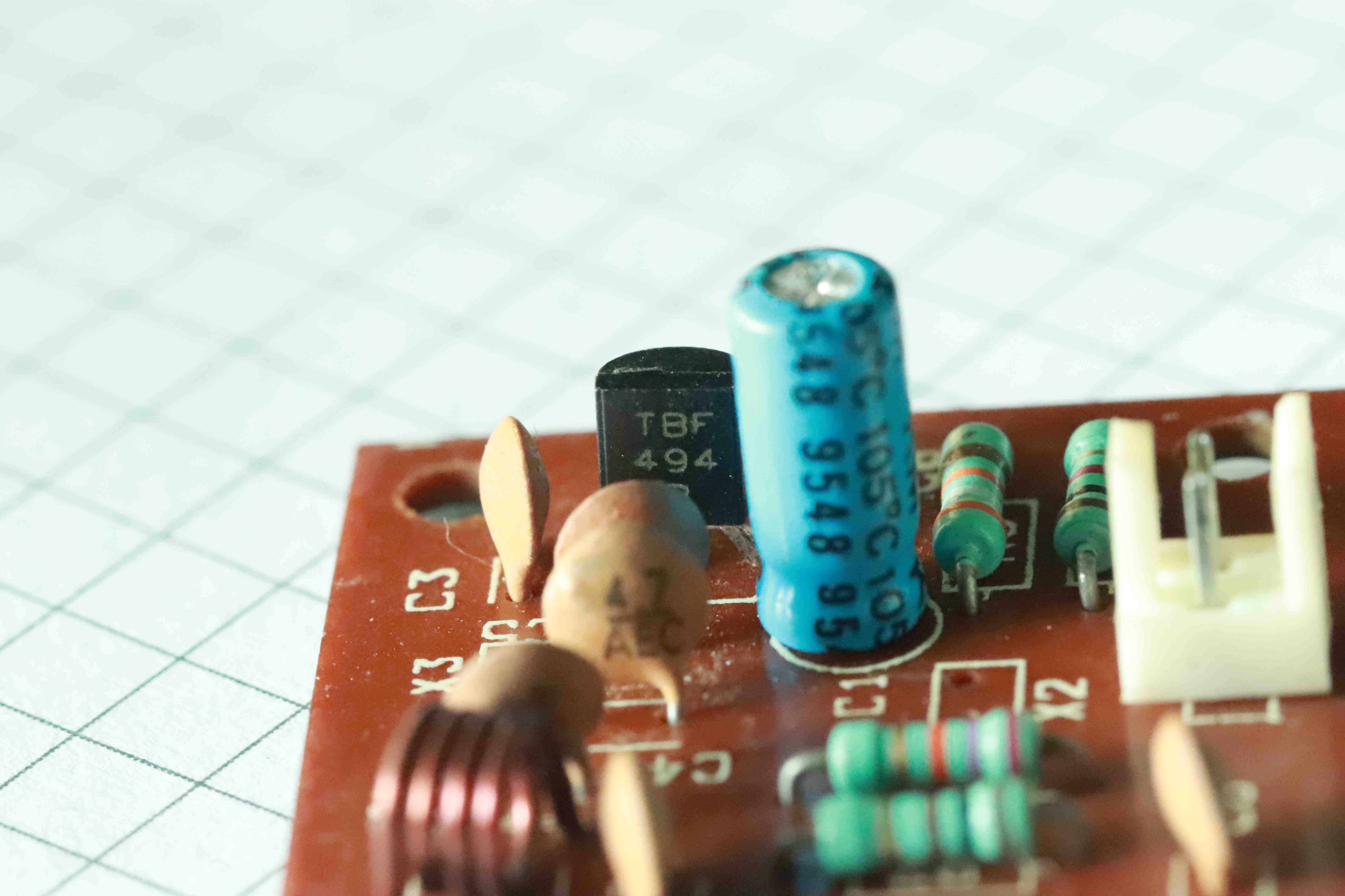
We are using BF494 transistor with TO-92 case. This transistor is capable of operating beyond our band and having enough hFE gain.
The LC tank circuit can be easily calculated. But due to parastic capacitance and inductance along with printed circuit board material, layout, components placement changes our effective LC tank values and oscillator center frequency.
The LC tank circuit and Q-factor of the circuit can tuned to our requirement by trial and error method.
Connector X3 is provided for adding external antenna. We can add few centimeters of wire into the connector X3 for effective radiation.
After assembly just apply 3V power to the transmitter. Keep a standard FM receiver ON. Depends on the country and region the FM may change. We can also inject a test signal into the connector X2. If our transmitter is within the FM band frequency then we will receive the test sound signal on the standard FM radio.
Once we are able to hear the test sound on any nearby FM radio then we can confirm that our transmitter is OK and we can proceed to construct our own FM receiver.
We can change the inductor diameter, SWG size, number of turns or gap between the winding to adjust our oscillator frequency to fall in the standard FM band.
This simplifies our effort if we have access to very limited test equipments. Since the transmitter is MONO we can construct a simple MONO FM receiver instead of STEREO receiver. Even with a STEREO FM receiver there is an option to force the receiver to operate in MONO mode.
RECEIVER:
Since we need a simple MONO fm receiver we will look for low cost FM only MONO receiver to reduce our design complexity and reduce BOM cost and board size.
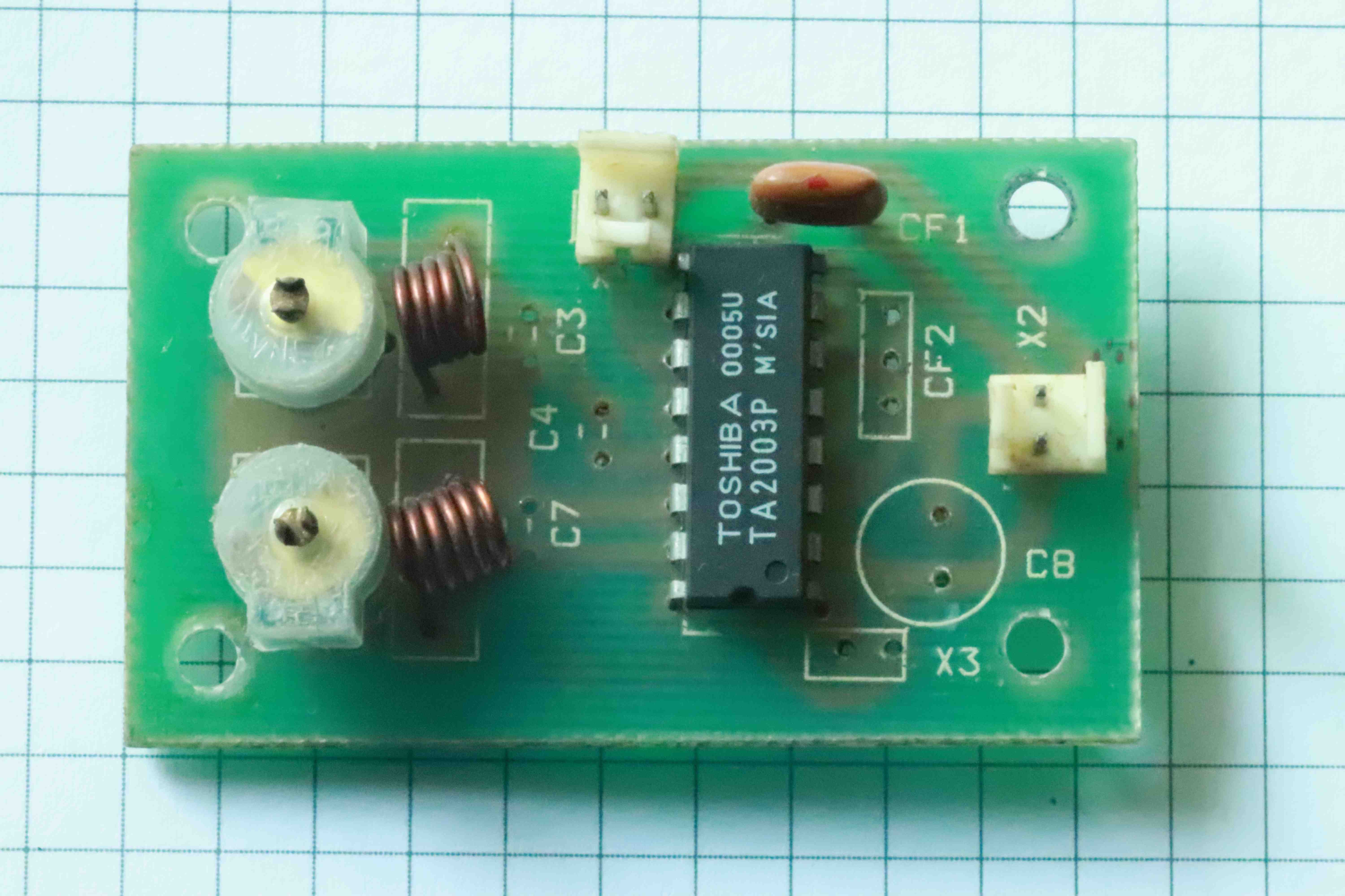
Depends on availablity, cost, DIP-16 package and less BOM cost we will settle down with the above IC. It requires just six components to receive good MONO FM signal.
Since we are going to operate our MONO FM receiver with a single carrier frequency, there is no need for variable gang capacitor. This will save some cost and board space. Even if we are using the gang capacitor, still the LC tank tuning requires the same effect. So there is no technical advantage of using gang capacitor.
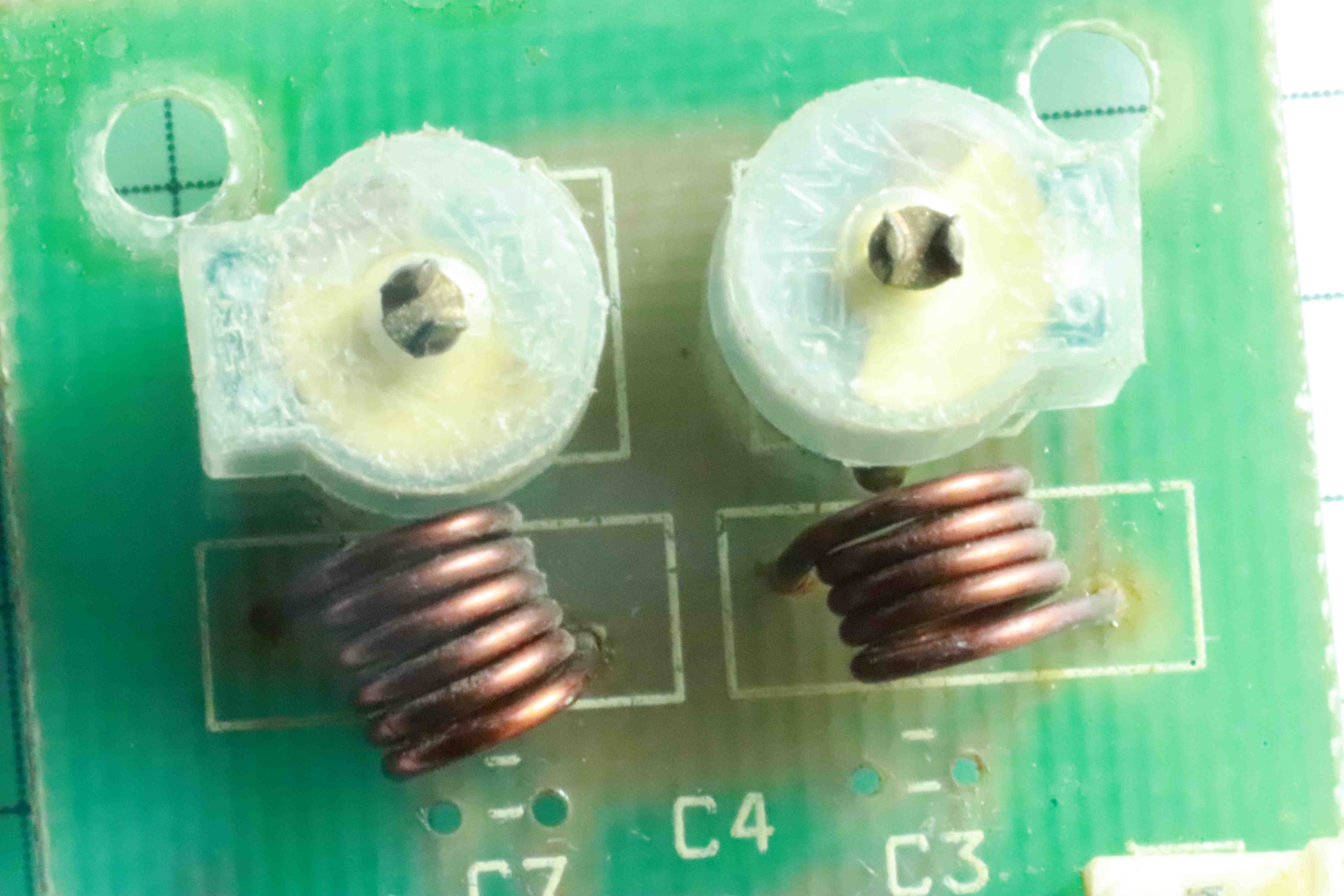
Now comes the fun part. We need to tune the LC tank circuit to match our transmitter frequency. There are two LC tank circuits required for operation. One LC tank is for RF input frequency and the other LC tank is for local oscillator. And the difference between the two LC tank will be your IF frequency.
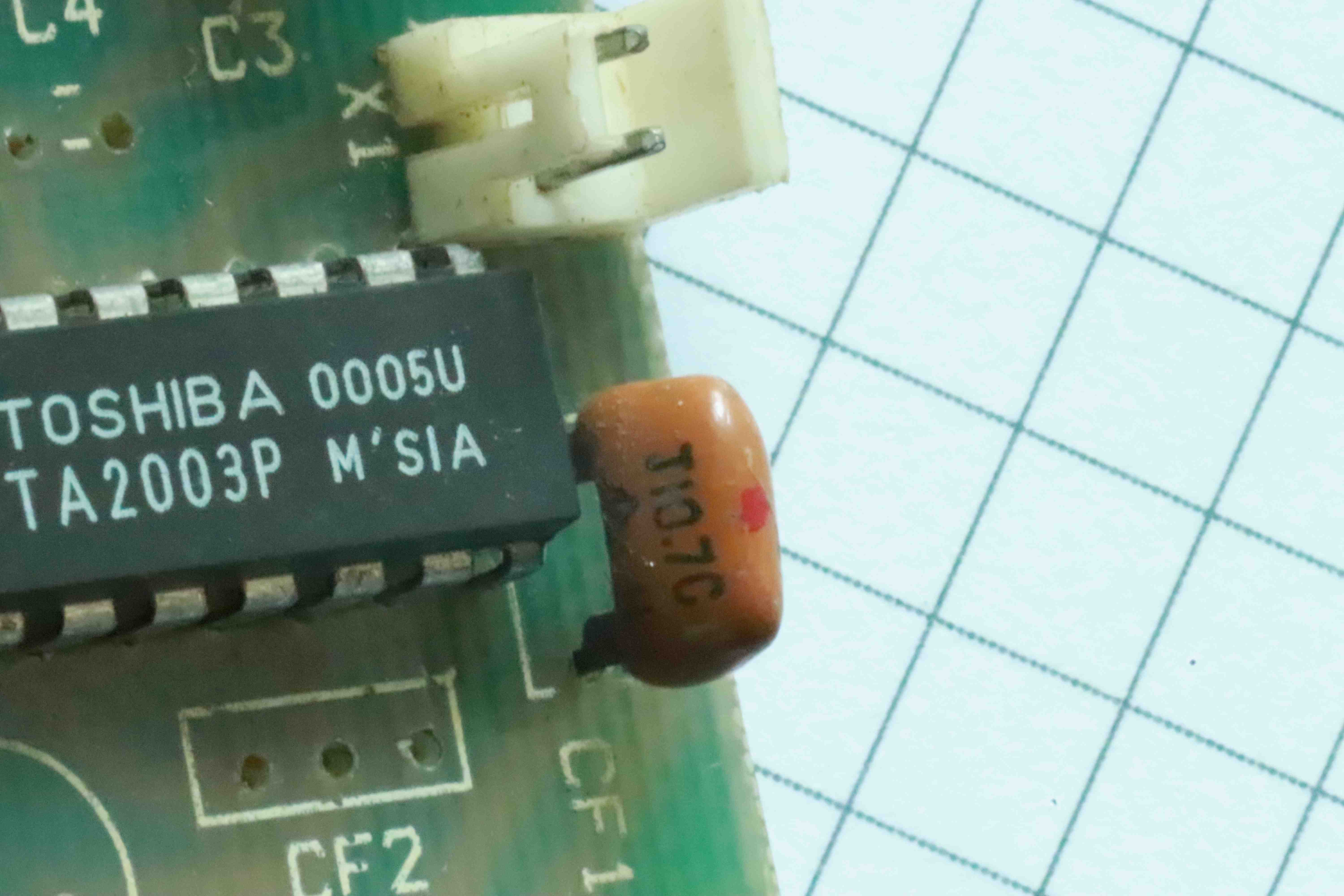
Now we will add the 10.7MHz IF filter. With this we have completed our MONO FM receiver using just six components.
We need to add antenna for our receiver by adding around 80cm of single strand wire. Now the receiver is ready and we can connect the 3V power supply.
For easy testing we can enable our transmitter and inject a 1kHz test signal. Now adjusting the LC tank at the receiver we will be able to receive the signal. We can test with a DSO or a simple low power audio amplifer and a small speaker connected to the demodulated output of our MONO FM receiver. We can also use a standard tuning gang capacitor to know the required capacitor for perfect tuning. But we need to have a capacitance measuring instrument to measure the capacitor value for local oscillator and RF section of the gang capacitor after disconnecting from the circuit.
It is difficult to tune for the first time. Once we know the inductance and capacitance value, it is very easy to tune very quickly.
Now we have successfuly constructed and implemented our RF channel. It is perfectly aligned and tuned to transmit and receive.
UART COMMUNICATION:
As we know the UART output from the microcontroller is unipolar and square wave digital signal(Without any level translator). Now we need to connect the Tx output of our microcontroller to the modulation input of the FM transmitter. The microcontroller can operate on any power supply voltage. Mostly assume either 5V or 3.3V.
We can directly connect the Tx pin of the microcontroller into the transmitter modulation input through a resistor and a capacitor in series.
-----/\/\/\/\/\---------| (-----
Rs Cs
Depends on the logic voltage of the microcontroller the Rs value will change. For 5V microcontroller it will be higher than the 3.3V operation. We can use 100k, 150k, 220k, 270k, 330k.
For easy testing we can use a frequency generator with 50% dutycycle with 3.3V and 5V amplitude. Since the FM receiver operates on PLL principle, the frequency deviation of the carrier should be within the FM receiver specification.
Even if we modulate perfect square pulse, we will not receive a perfect square pulse at the MONO FM receiver. So we need to waveshape the received output signal and have an additional comparator with variable threshold to achive the required dutycycle and pulse width to match the original digital UART signal timings. Only after waveshaping and logic level conversion we can use the received digital signal for error free operation.
So we need to perform three operation on the the received UART signal from the MONO FM receiver.
- Amplification (toward square wave)
- Comparator with variable threshold
- Logic level compatibility
These are not very critical and any general purpose OP AMP will do the job. We will go with UA741.
OP AMP POWER SUPPLY:
We will operate the OP AMP on rail to rail power supply with bipolar 12 volts.
We will go with linear power supply using LM7812 and LM7912 both in TO-220 package.
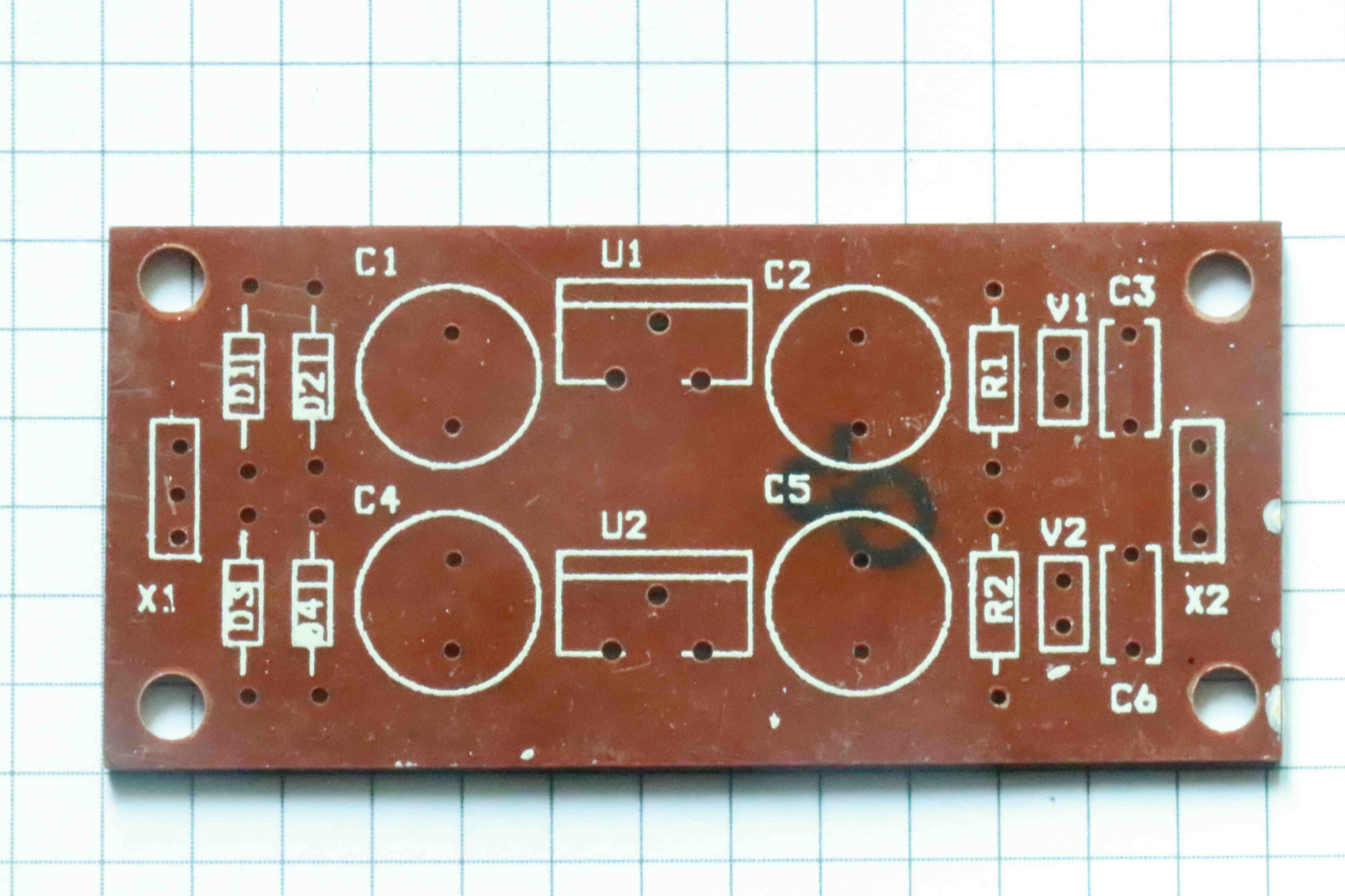
After assembly. LED V1 and V2 are indicators. C6 and C6 are decoupling capacitors. C1, C2, C4 and C5 are Bulk Capacitors. R1 and R2 are 1.2k. Diodes D1-D4 are full bridge rectifiers.
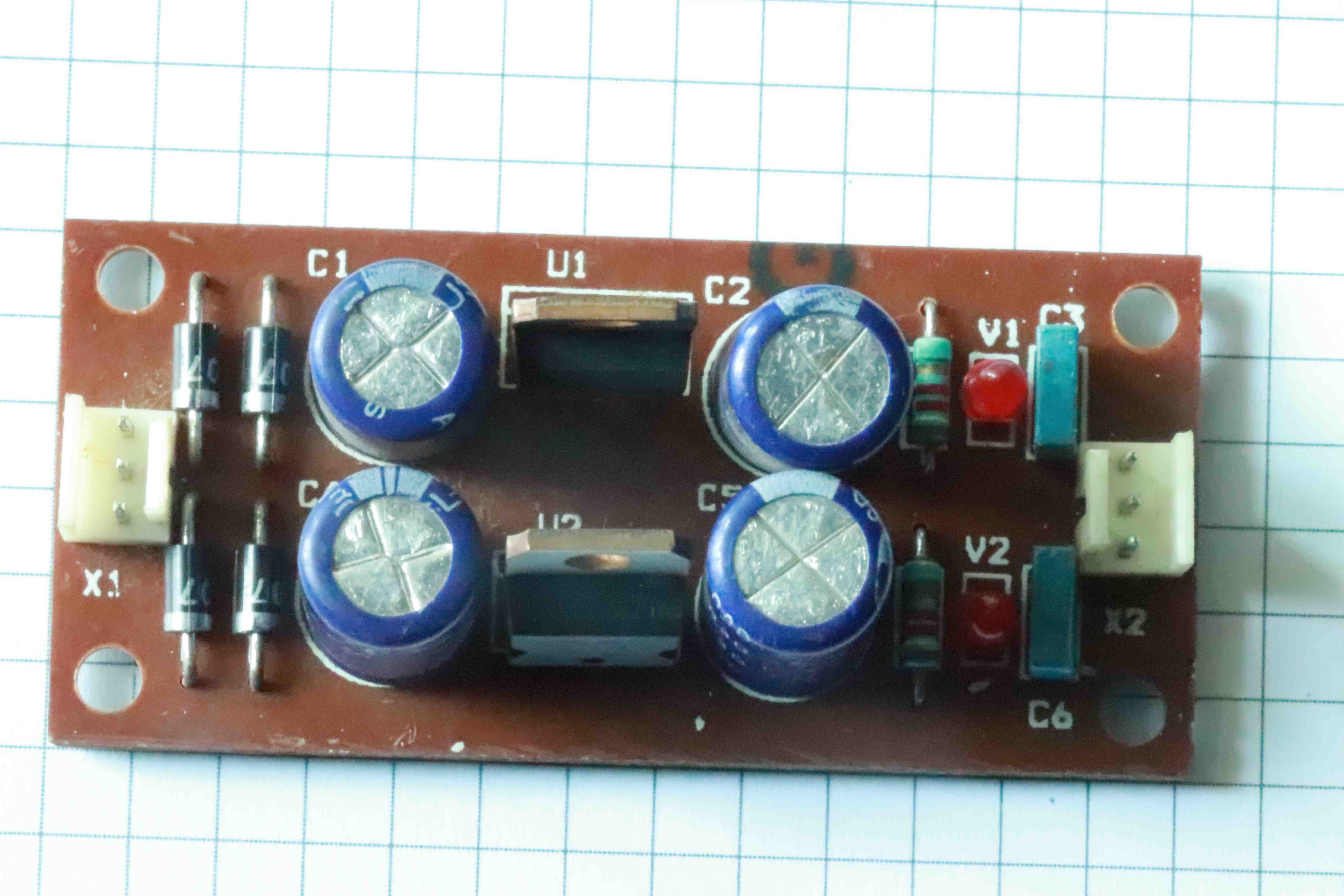
After assembly the OP AMP power supply is ready for testing and integration.
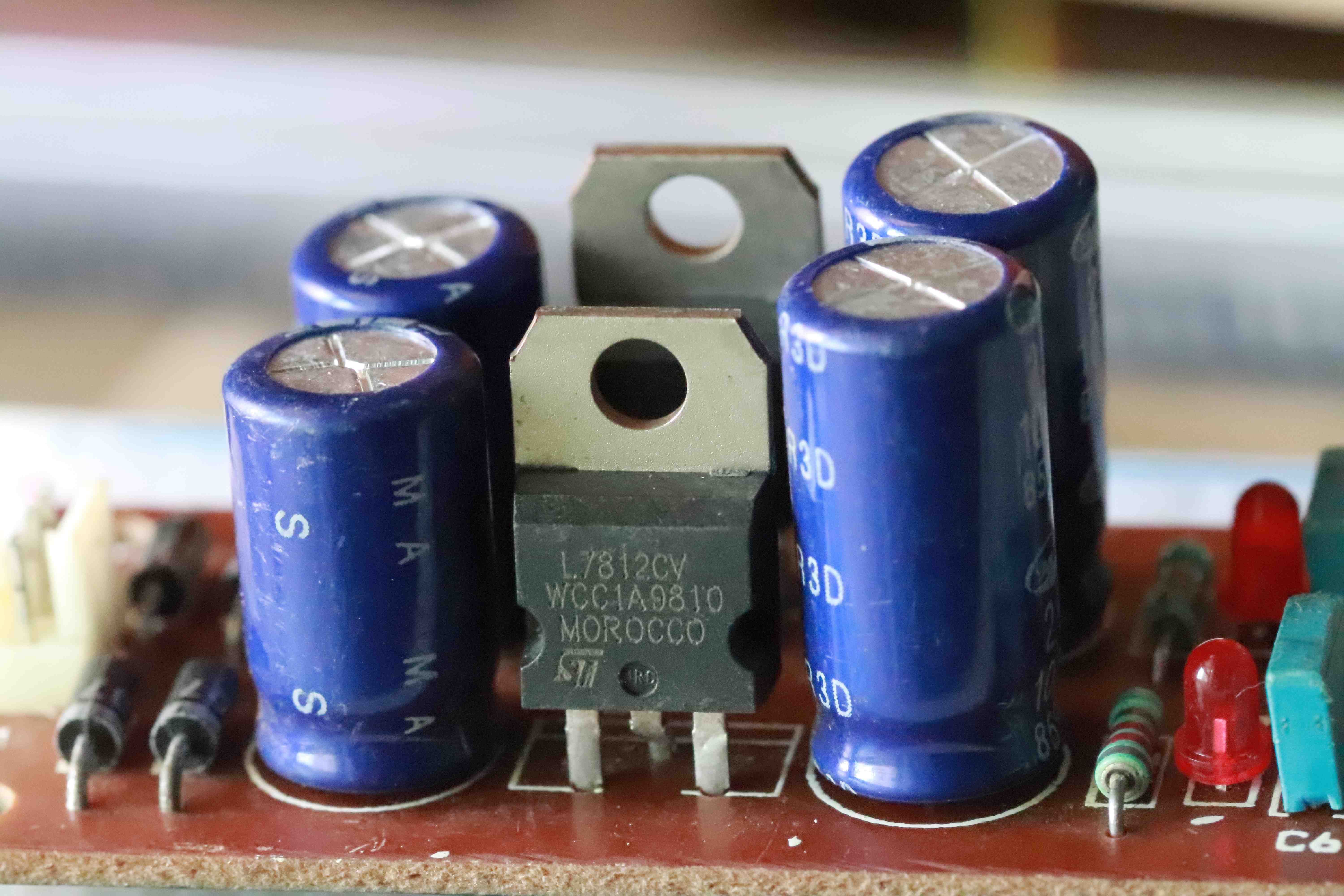
L7812 in TO-220
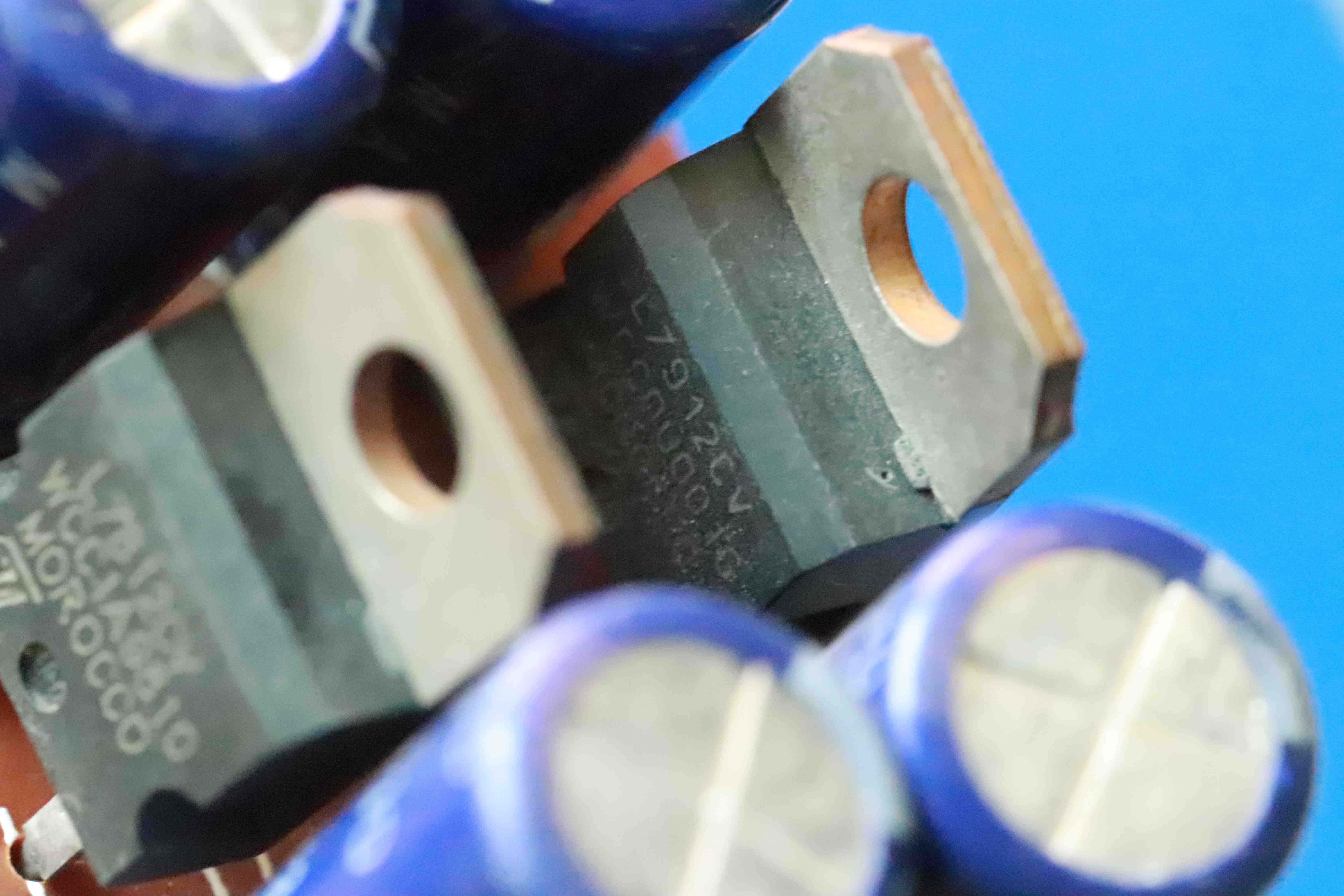
LM7912 in TO-220
So now we successfuly completed our OP AMP board power supply. We can test and make sure the output are within limits.
AMPLIFIER AND COMPARATOR:
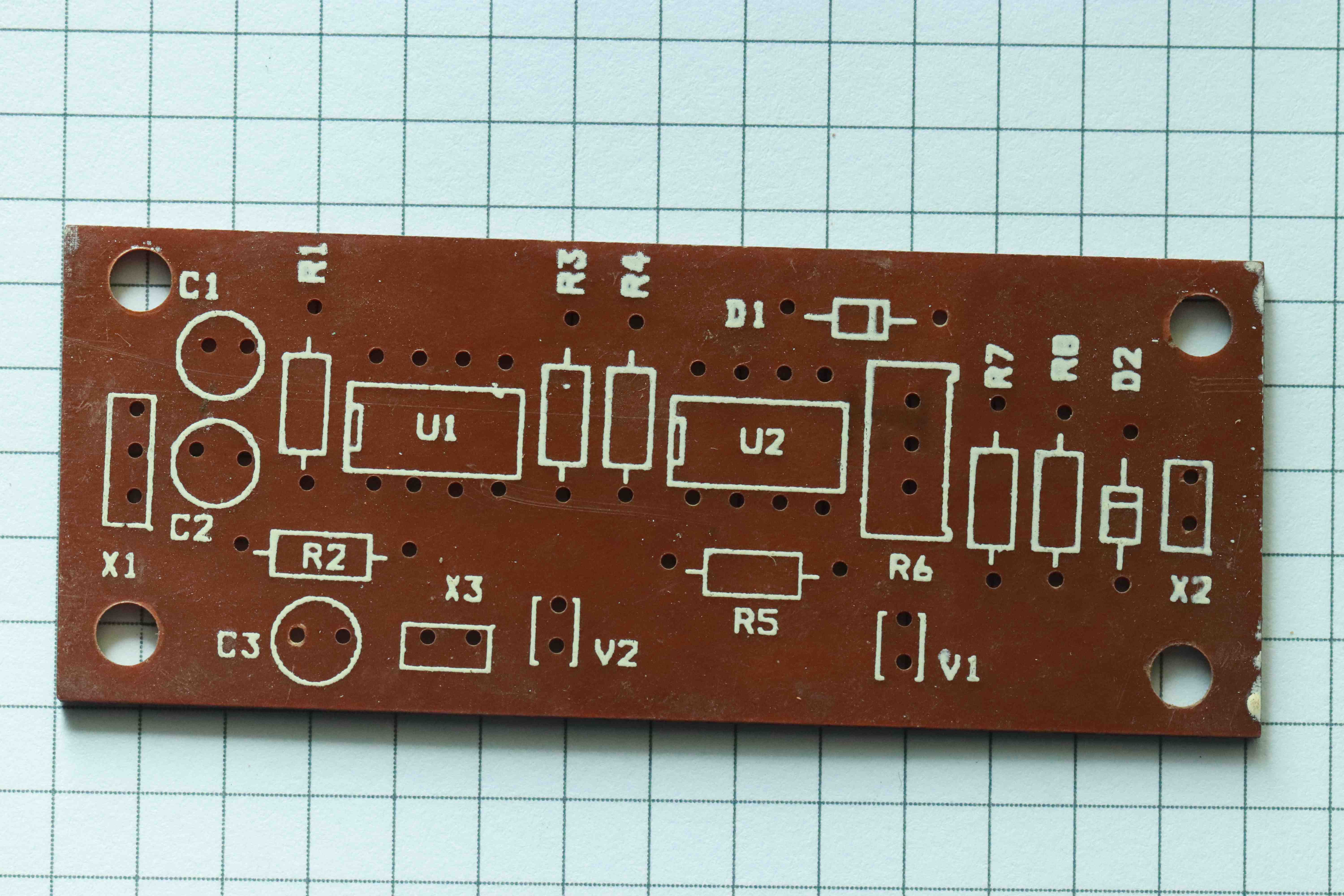
The amplifier and comparator is now ready for assembly. U1 and U2 are UA741 OP AMPs. IC U1 used as an amplifier and IC U2 used as a comparator. Variable resistance R6 used to set the comparator reference. Small signal diode D1 used to clip the negative part of the output wave to make it compatible with digital logic of the microcontroller. Zener diode D2 used to clip the maximum logic level of the output voltage. For 3.3V microcontrollers we can use 3V3 zener diode and for 5V microcontroller we can use 4V7 or 5V1 zener diode.
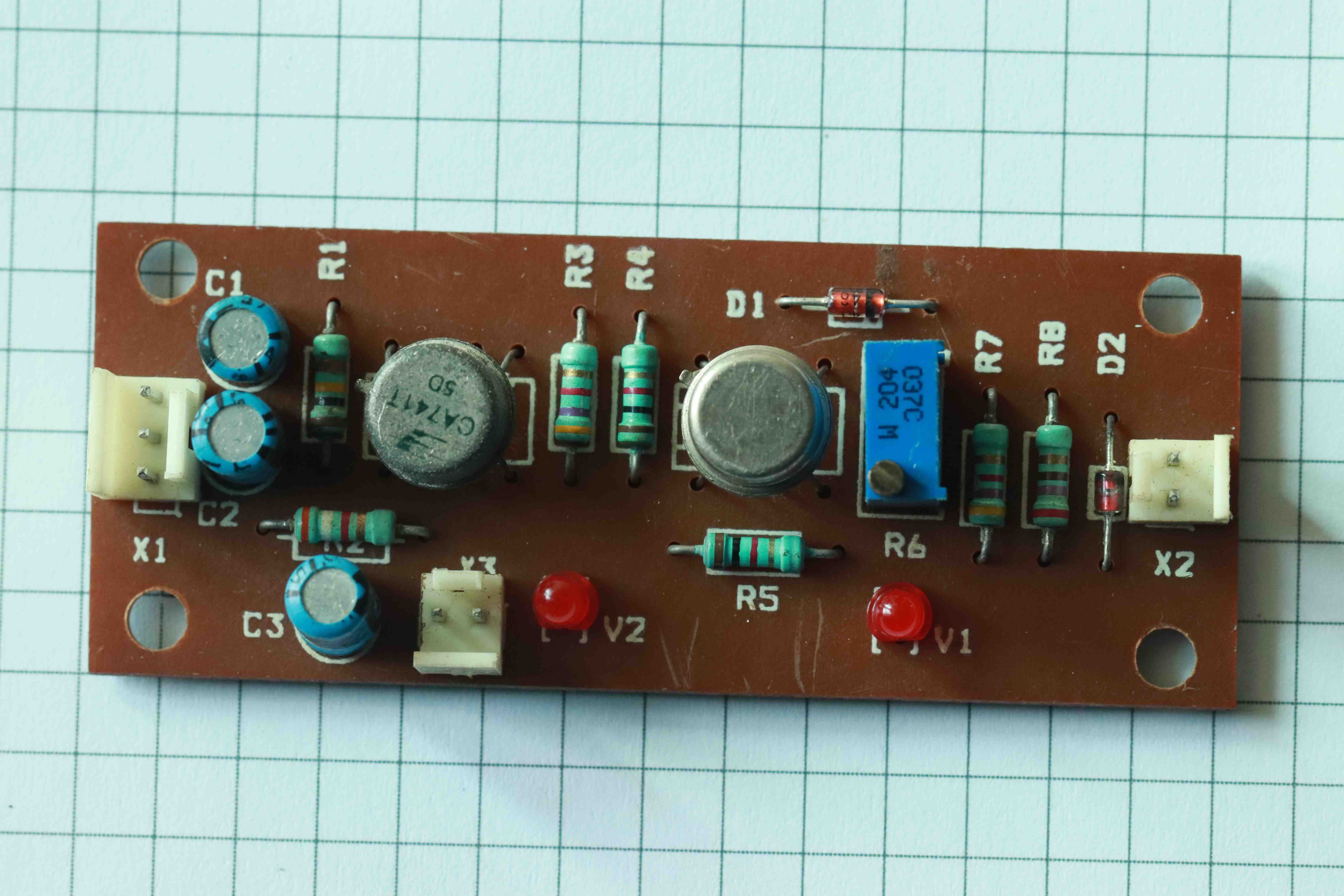
The IC U1 is configured as AC coupled amplifier with a gain of ~25. The IC U2 is used as comparator. IC U2 almost acts as zero crossing detector with open loop gain. The threshold can be adjusted using R6 variable resistor. LED V2 and V1 are just visual indicator of the received UART signal. Diode D1 is a small signal diode(1N4148). After the comparator the voltage swing is rail to rail(+12 to -!2). The diode clips the negative swing. Diode D2 is a zener diode which needs to match the safe logic operation of the microcontroller.
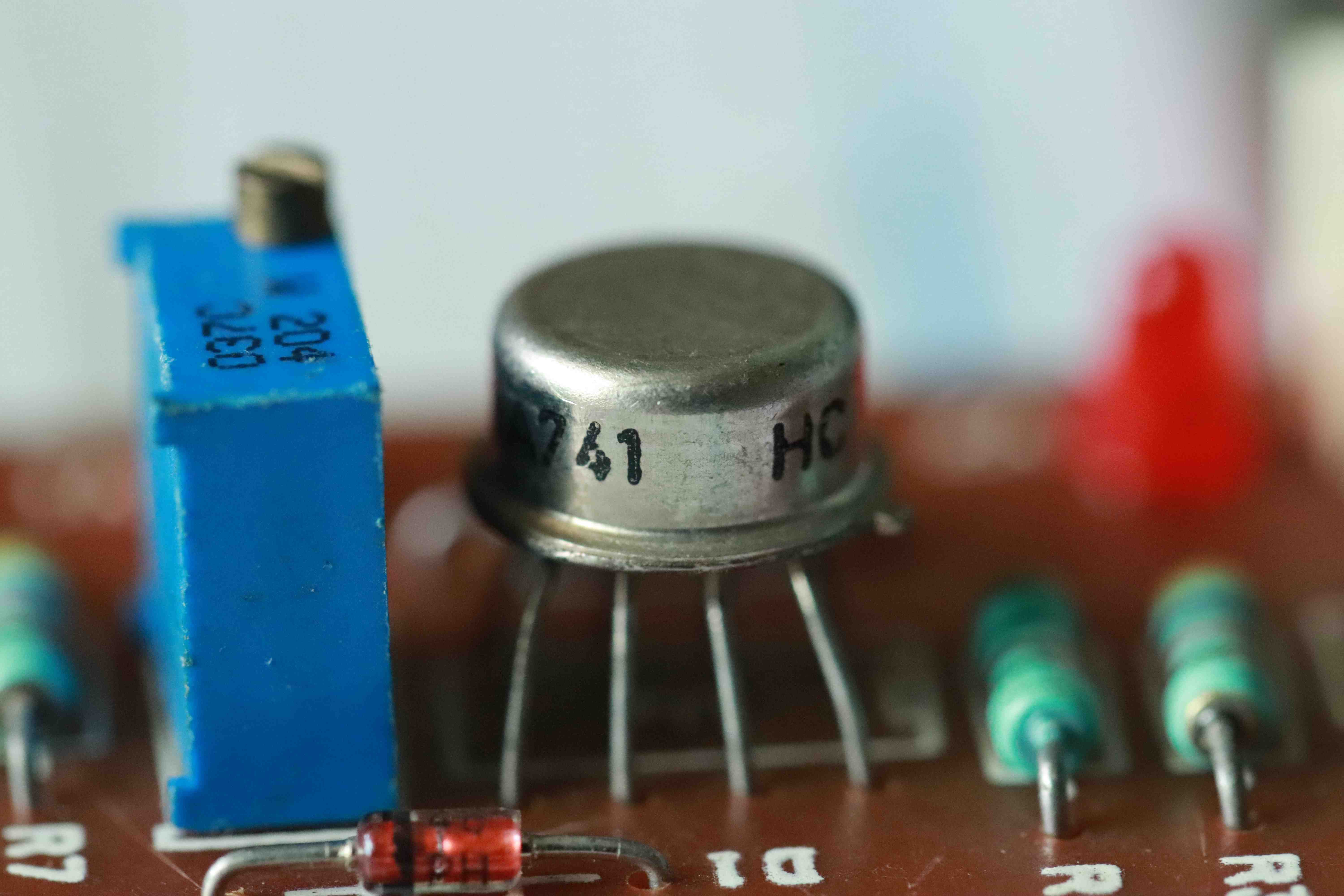
IC UA741 used as comparator in METAL CAN package. D1 small signal diode 1N4148 seen in the front.
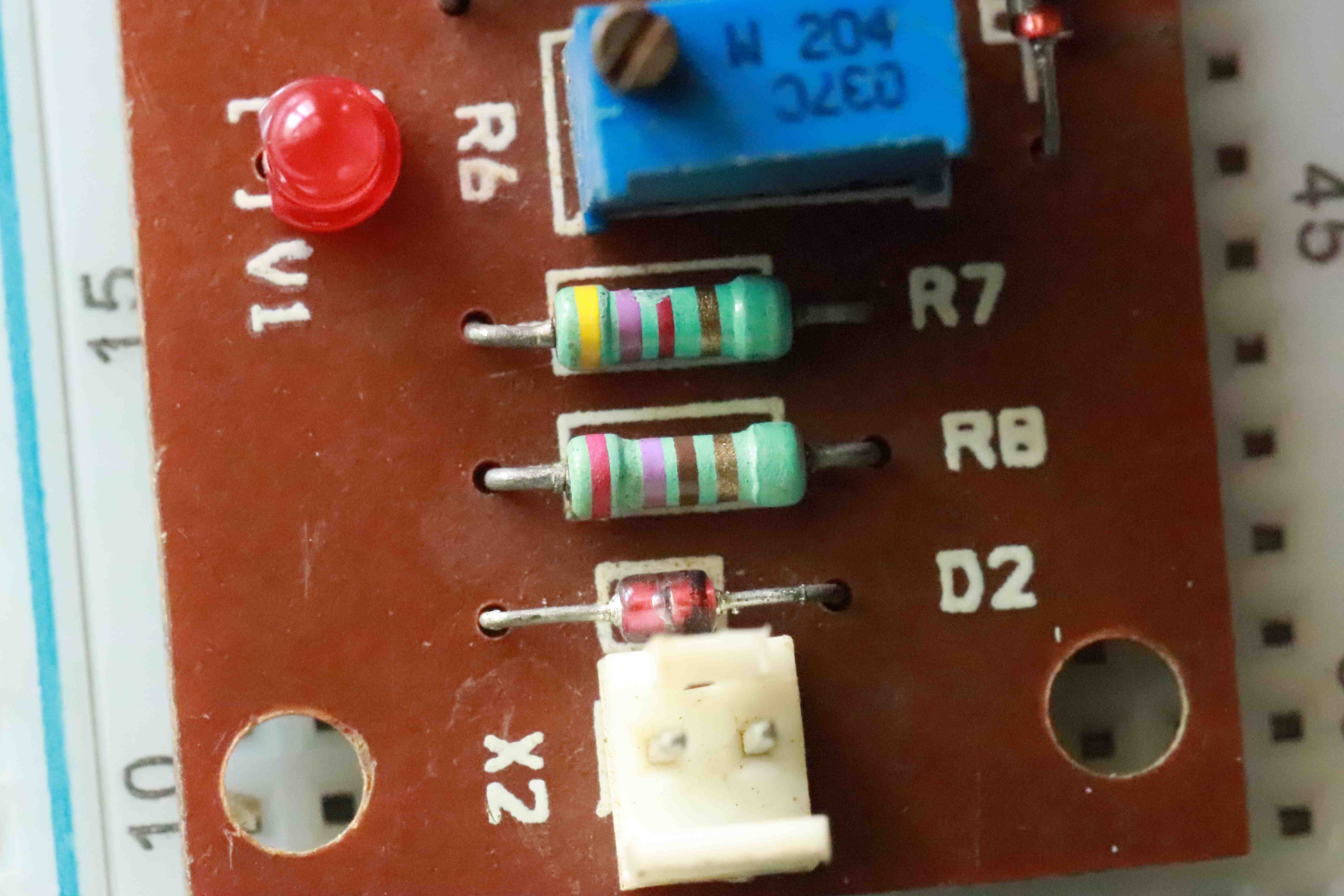
Zener diode with series resistor R8(270 ohms) and LED V1 current limiter R7.
So we have successfully implemented a FSK modulator and de-modulator using simple and available inexpensive components.
What else I can use this circuit?
DTMF transmitter and receiver:
We can use this RF transmitter and receiver for transmission and reception of DTMF signals without any modifications.
DTMF GENERATOR:
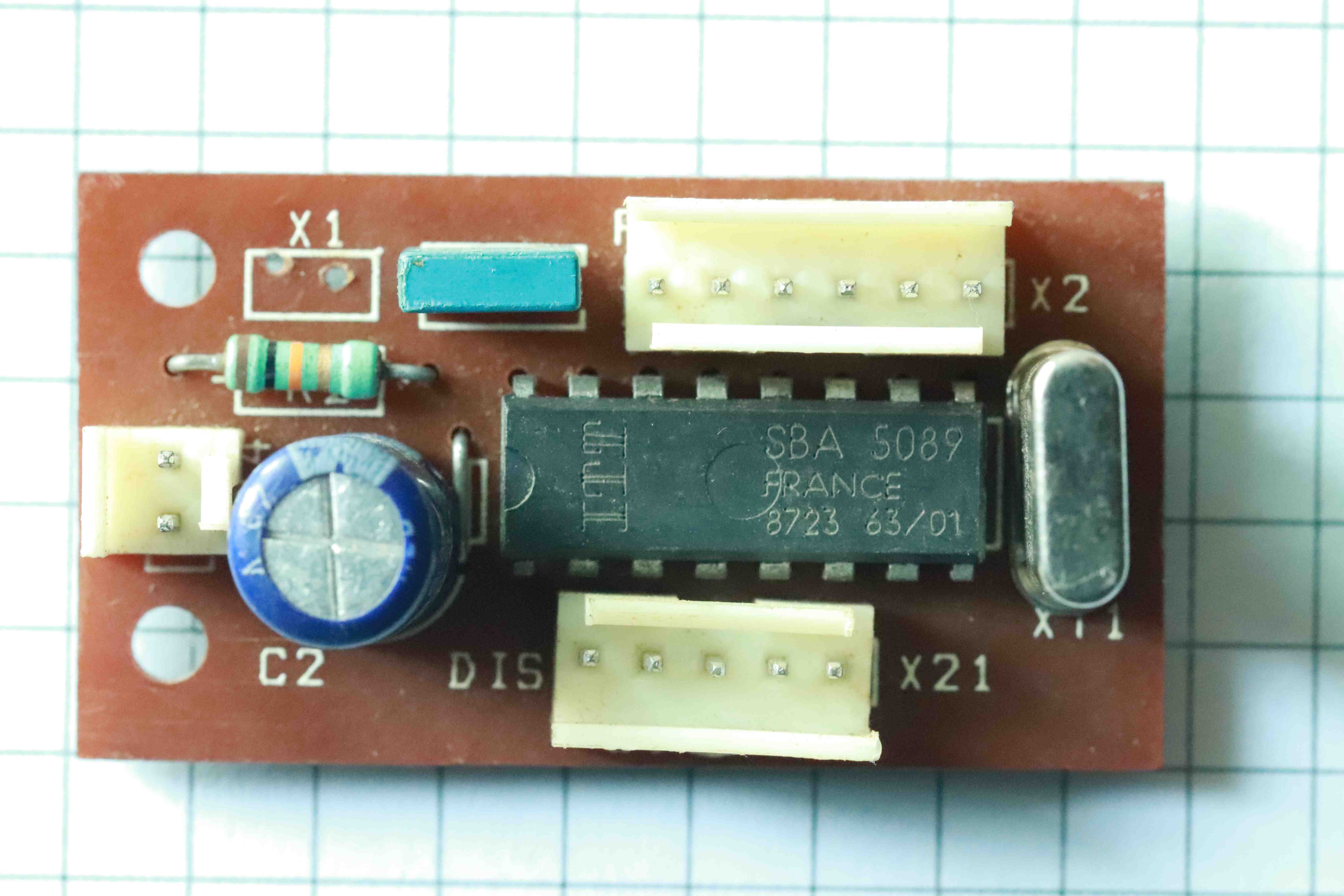 It is a simple 5089 DTMF(Touch-Tone) signal generator. We need to connect a 3.58MHz crystal X2 and a 10k resistor to enable the tone. X21 and X2 connector having all the ROW and COL signals to interface with a matrix keyboard or any mechanical switches.
DTMF RECEIVER:
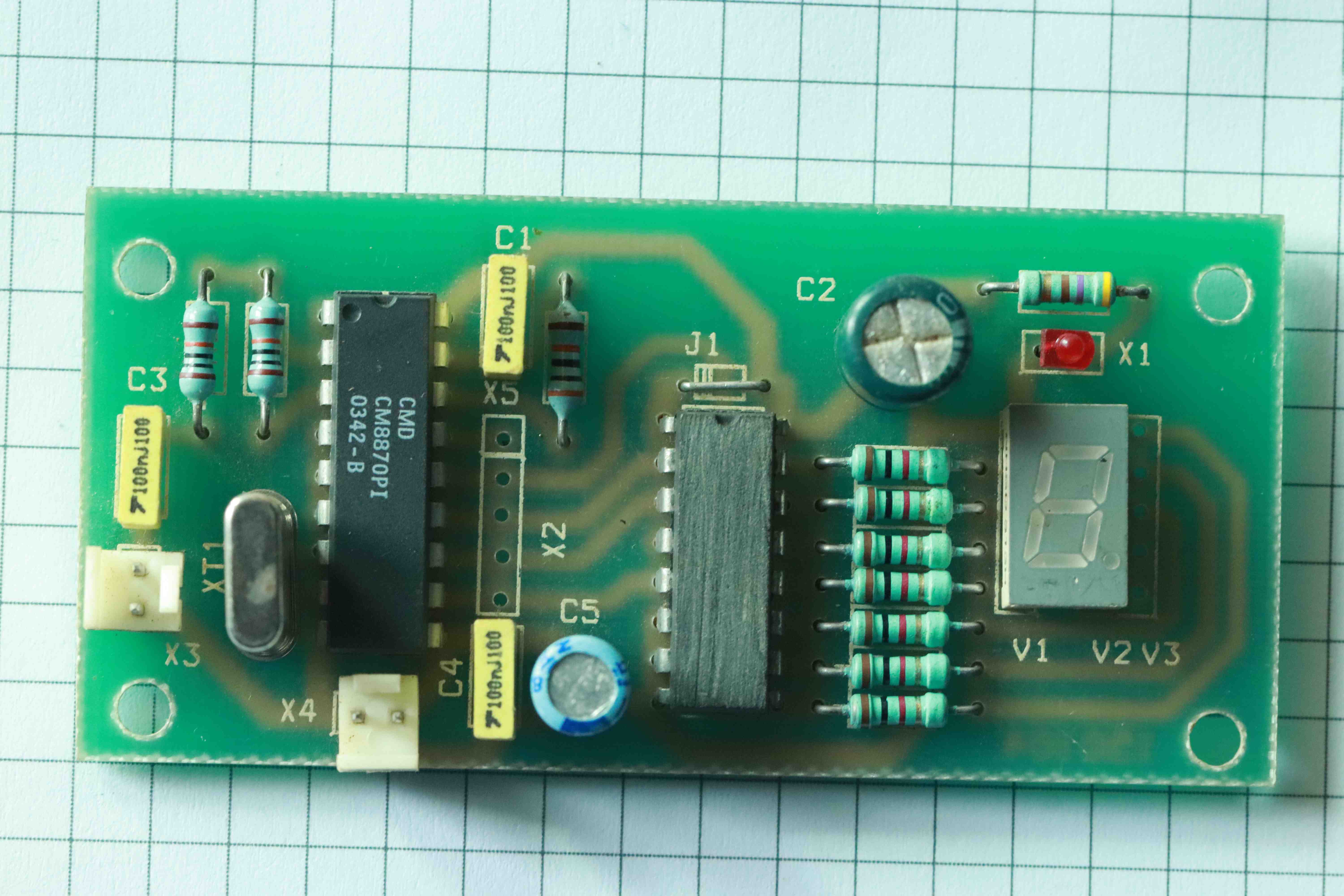
The DTMF receiver is based on CM8870 IC. The DTMF receiver requires 3.58MHz for operation. The received binary digital logic is available in the X2 connector for decoding and interface. For stand alone operation and easy testing there is a onboard BCD to seven segment decoder along with display is implemented.
If we connect the DTMF generator tone output to RF transmitter modulator input and connect the DTMF receiver to the MONO FM receiver directly bypassing the OP AMP amplifier and comparator, then we can send the DTMF signals over the RF link and decode it at the receiver end.
This can be very useful with the remote control operation without any intelligence or circuits without microcontrollers.
What else I can do with the RF transmitter and receiver?
MAL(Monaural Audio Link):
You can inject music or song and listen it remotely.
What else I can do with transmitter and receiver?
You can simple connect a microcphone and speak or sing!