 Lithium ION
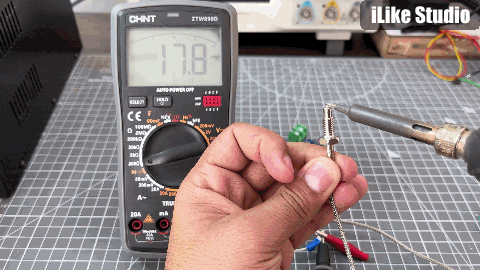
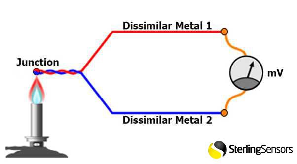
A K-type thermocouple is a type of temperature sensor that is widely used in industrial applications to measure temperature. It is made up of two different metals, typically nickel-chromium and nickel-aluminium, which are joined together at one end to form a junction. When the junction is exposed to a temperature difference, a voltage is generated, which can be measured and used to determine the temperature.
Then we will design a PCB shield using the custom PCB manufacturing service, so that components like Arduino and sensor module can be plugged directly without soldering through pin headers.
Composition of K Type Thermocouple:
In K Type Thermocouple positive leg is composed of 90% nickel, 10%chromium and a negative leg is composed of 95% nickel, 2% aluminium, 2% manganese and 1% silicon. These are the most common general-purpose thermocouple with a sensitivity of approx 41µV/°C.
Temperature measurement in K type sensor:
The principle behind how a thermocouple works is called the Setback effect, which states that when two dissimilar metals are joined together at two different temperatures, a small voltage is generated. The amount of voltage generated is proportional to the temperature difference between the two junctions. The K-type thermocouple generates a voltage of approximately 41 microvolts per degree Celsius.
Comparison with other temperature sensors:
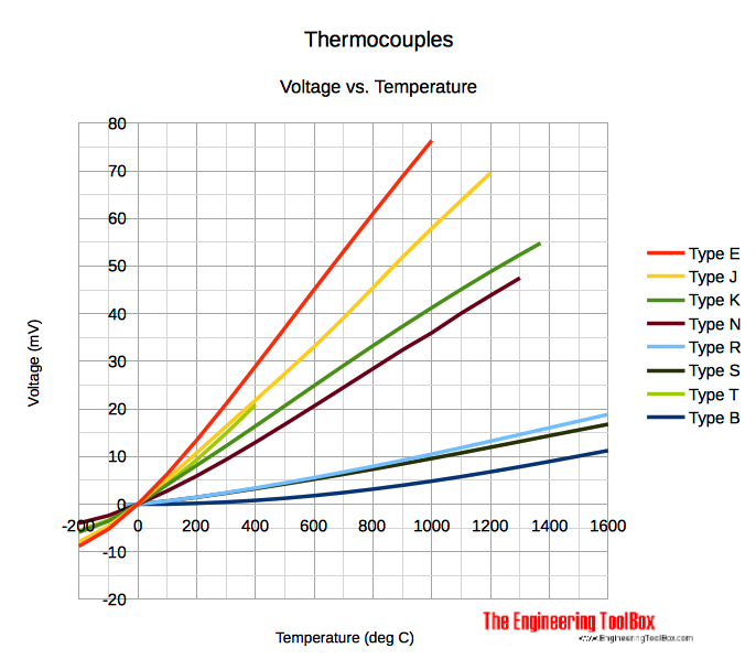
Other temperature measurement transducers like PT-100, PT-1000 and NTC are linear in a very small range. Overall temperature measurement bandwidth is very less.

These sensors are not made to measure a temperature above 300°C but K type transducer give a very good range of over 1200°C. in this sensor no calibration is required the internal compensator circuit adjust accordingly and data is supplied digitally with 12-bit precision.
MAX 6675 Precision Amplifier:
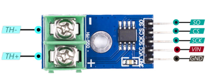
The MAX6675 is a thermocouple-to-digital converter IC that can read the voltage output from a K-type thermocouple and convert it into a digital temperature reading. The amplifier in the MAX6675 has a gain of 8, which means that the output voltage of the amplifier is eight times larger than the input voltage from the thermocouple. The amplified voltage is then fed into an analog-to-digital converter (ADC) that converts the voltage into a digital temperature reading.

The MAX6675 also has a built-in cold-junction compensation (CJC) circuit that compensates for the ambient temperature at the junction of the thermocouple and the MAX6675. The CJC circuit measures the temperature at the junction and subtracts it from the temperature reading obtained from the thermocouple to provide a more accurate temperature measurement.

Features:
- Direct Digital Conversion of Type -K Thermocouple Output
- Cold-Junction Compensation
- Simple SPI-Compatible Serial Interface
- 12-Bit, 0.25°C Resolution
- Open Thermocouple Detection
Components Required:

1) K-Type Temperature Sensor
2) Arduino NANO/UNO
3) OLED display
Circuit diagram and PCB:

I made the circuit using Altium designer, this is the shield having headers for K type temperature sensor, Arduino nano, OLED display and battery. Just plug all the components/ peripherals in the shield and we are ready to go.
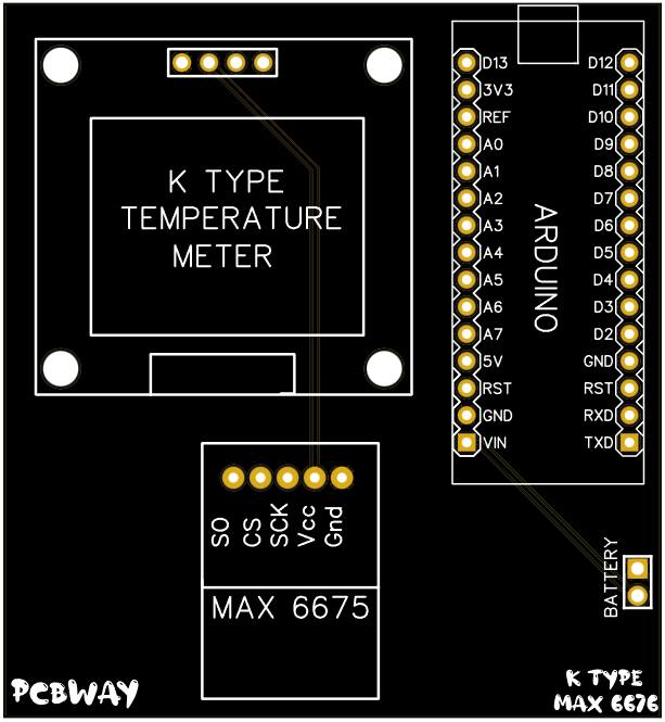
In the circuit there are very less number of external components. Because of digital interface the data and clock lines are shared with the microcontroller and final output contains the decoded data. Download the Gerber files, code and circuit diagram.
Interfacing with Arduino:
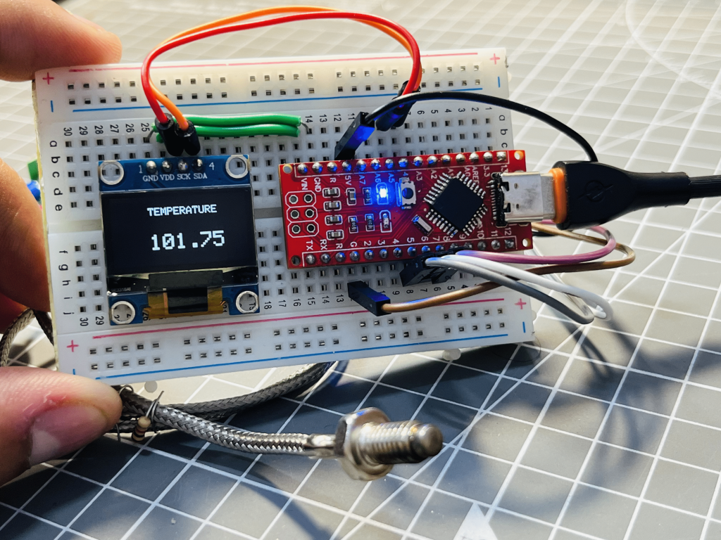
In the figure the basic circuit of MAX6675 amplifier and Arduino is shown. The connections are done according to the below given program. A small OLED panel is used to show the temperature readings on it. The sensor is refreshed after every 500ms, so we got the real time readings of temperature w.r.t time.
Program for Arduino:
First of all the MAX6675 Arduino library is required, this will...
Read more »
 Sagar 001
 Arduino KIT
 Daphne