While working with my hot plate soldering project an idea comes into my mind. Why not to make a super simple are precision temperature sensor which can measure up to 500 degrees on a linear scale. There are many thermocouples, thermistor, NTC and PTC type of temperature measuring units available in market. But due to their nonlinear properties and lower temperature range measurement of hot plate cannot be done.
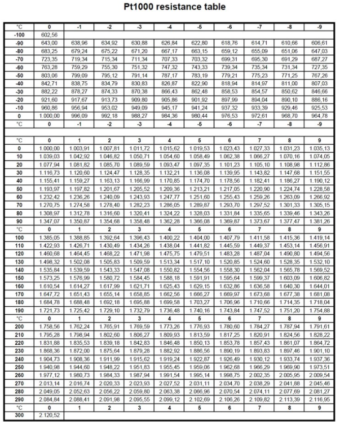
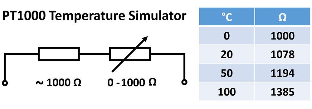
That’s why I came with a new sensor which is based on platinum thin wire. The resistance of any metal change with change in temperature. Which follows the basic phenomena, atom start vibrating more and retard the flow of electrons through them. The change in resistor can be linear or non-linear based on the material and properties. The basic features and resistance table of a PT1000 is given below. Here is the Custom PCB service that you can use to order the same PCB design by downloading the Gerber files given below.
Pt1000 sensors (1000-ohm temperature sensors):
They are the second most common type of platinum resistance thermometer. Pt refers to that the sensor is made from Platinum (PT). 1000 refers to that at 0°C sensor has a resistance of 1000 ohms (Ω). The PT type of RTD is much most stable and precise (but also more expensive). PT1000’s is useful to measure temperature in laboratory and industrial processes; and have developed a reputation for accuracy (better than thermocouples), repeatability, and stability.
This high-temperature PT1000 sensor is equipped with a 316L stainless steel shield (try saying that five times fast!) that is good for up to 550°C.
Features:
Based on resistance measurement principles.
Resistor material is Platinum with a value of 1000 ohm at temperature 0°C.
Platinum has a positive resistance-temperature factor; resistance increases with rising temperature.
Resistance variation is a function of temperature: 3.85Ω/°C nominal.
High accuracy and stability compared to thermocouples, silicon-based temperature sensors, or thermistors.
How to measure:
The main problem with microcontrollers is that they can only measure the function of time or voltage. So here we have to convert the rise in temperature resistance value to respective voltage value which can be done by using simple voltage divider. But because rise in resistance is very less as compare to the temperature values the Arduino 10-bit internal ADC may not be able to understand the sudden change that’s why we need to amplify the signal with the help of operational amplifier and using a proper gain with the Arduino ADC the final value can be displayed on the screen.
By the way if you are not interested in this much then measurement can be done by a high resolution multi-meter. The table of resistance with respect to temperature is given here.
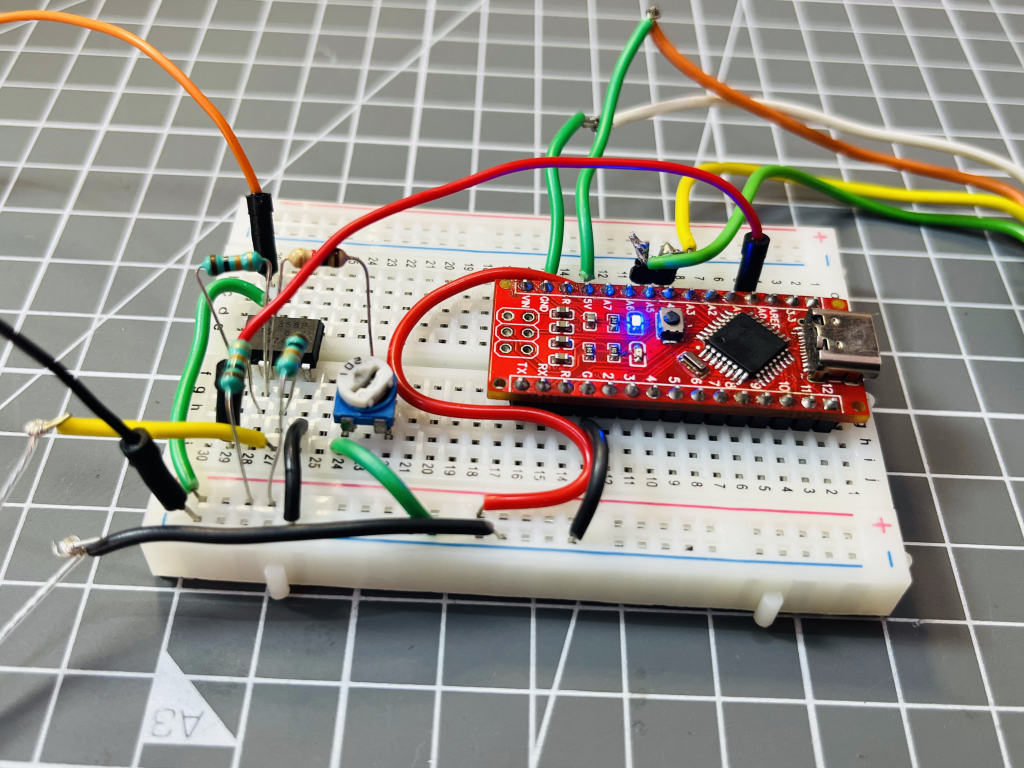
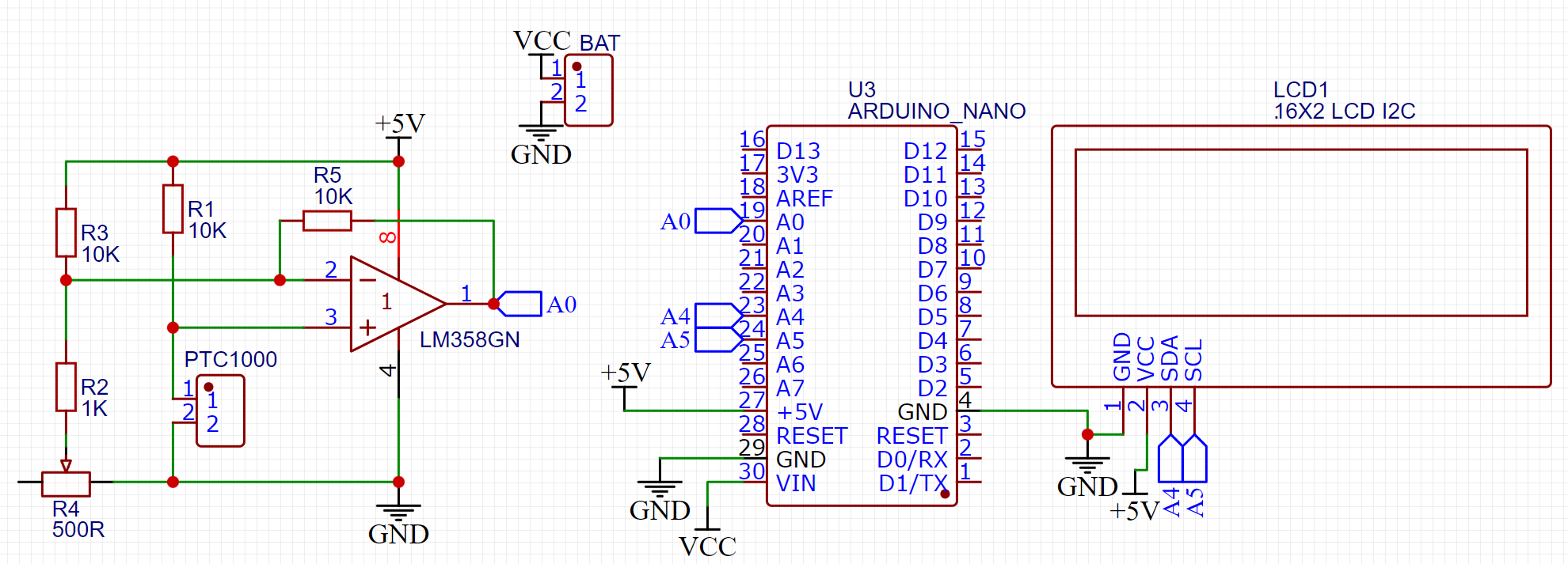
The concept of virtual ground is used here, we have to amplify the signal but first by using a voltage divider network with PTC the middle voltage is derived which can be used to detect the respective change in temperature but here we also need a reference which is designed using separate 10k and 1k resistor in voltage divider configuration. We know that temperature readings are 1000ohms exact at 0 degree Celsius. Then the amplification factor is determined. We are using the sensor at non-inverting terminal and the voltage difference between the both terminals is amplified. Which is a positive value and finally the code is designed to get the temperature readings out of this amplified voltage.
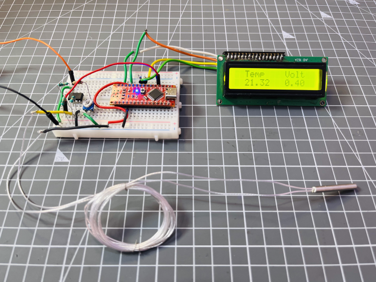
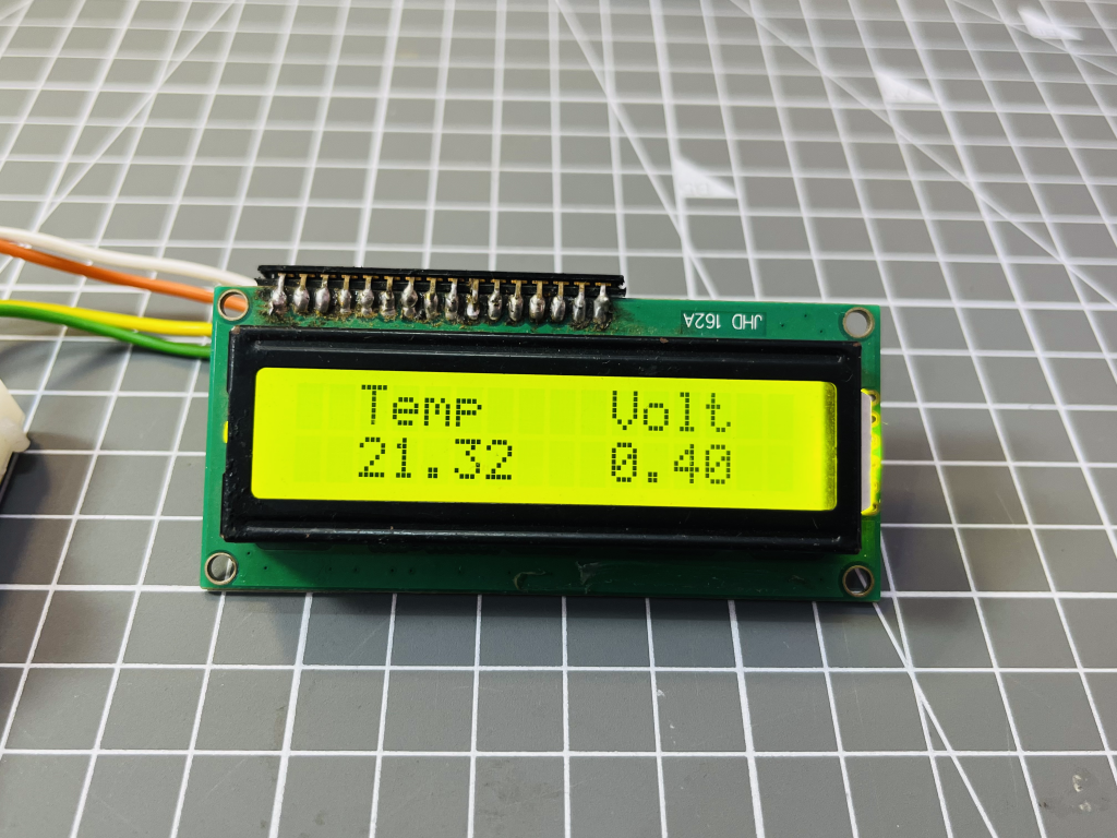
The output of operational amplified is connected to the A0 pin of the Arduino and the screen is connected via I2C interface. The code is designed to display the value of voltage at A0 and the temperature reading.
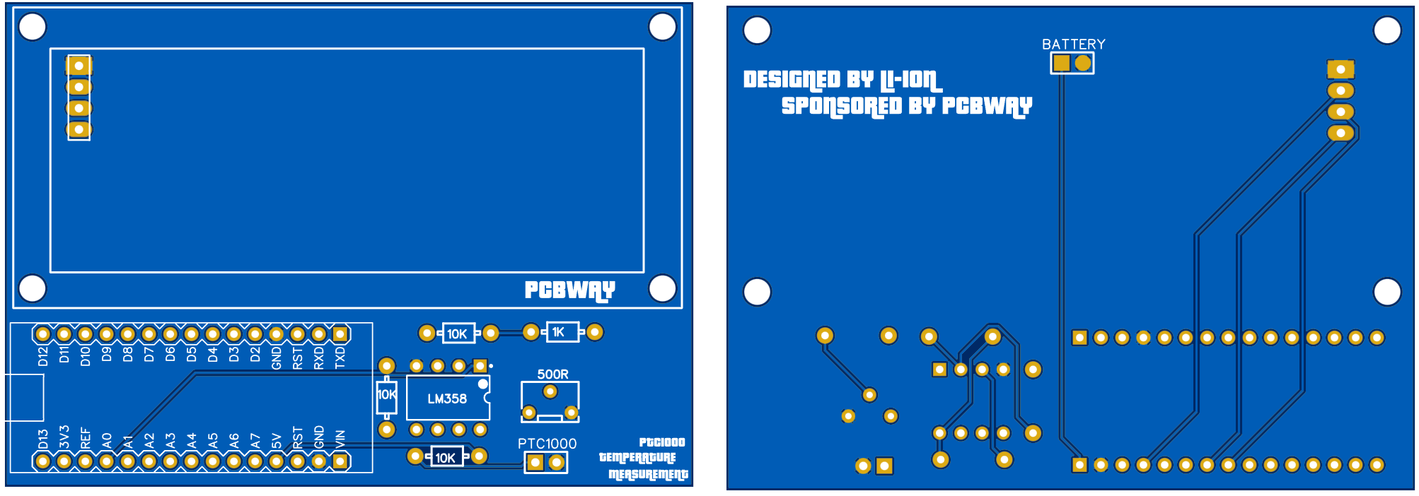
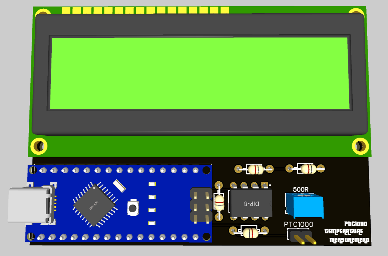
Gerber files and PCB design:
I designed the circuit diagram and converted it into PCB, here you can find the Gerber file which be directly used to order the same PCB. Or if you want to make some modification the Circuit Pdf is also shared below.
Arduino code:
I used the basic Liquidcrystal_I2C library for the screen which can be downloaded from the manage library section under the tool’s menu in Arduino IDE.
To calibrate the sensor we need a potentiometer because fixed carbon resistor may have error and power supply fluctuations are also present in the circuit. To minimize these values and to calibrate the temperature meter properly here are two methods.
1) By fixing the resistor value. A small value 1k resistor can be connected (as displayed in circuit diagram above) which can be tuned properly.
2) In the software the VT factor and Offset error value is given which can be modified as per used sensor. Vt_factor is simply the value of voltage to temperature measured at 100 degree and 0 degree.
VT_factor= 100 degree voltage – 0 degree voltage.
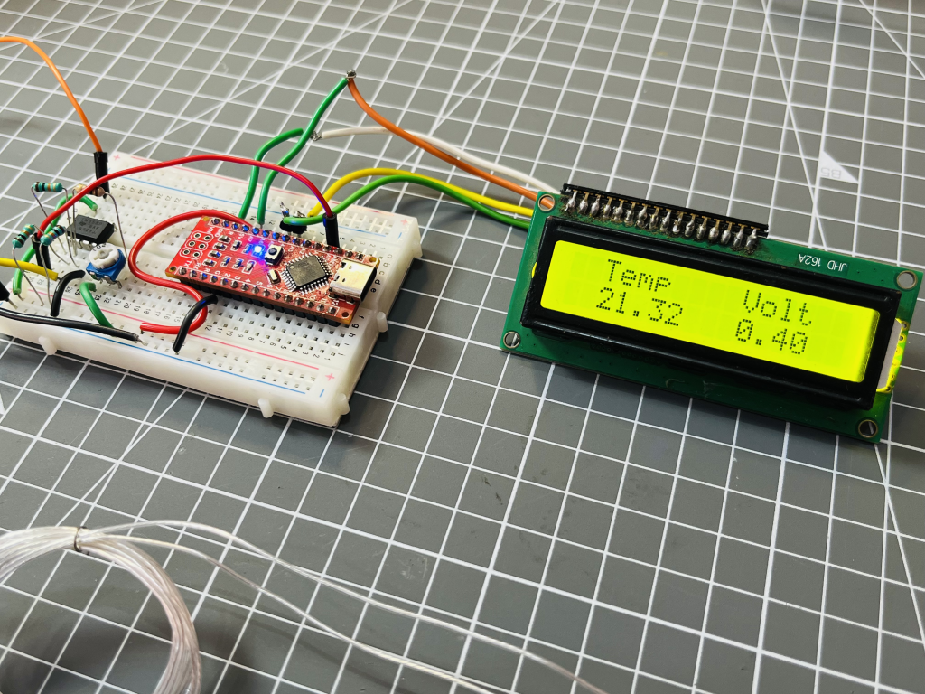
Measuring and testing:
Here is the testing procedure of this PT1000 temperature meter. The value of temperature is displayed accurately and well. Precision and accuracy depend on the used circuitry and calibration. Vt_factor play a very crucial rule here and every PT1000 may have different value.
Mine version of this temperature meter is working well and soon I will deploy it in my hot plate soldering equipment. In the next version of this meter I will try to make a small-scale possible model using any other MCU and multiplexing the screen with 7 segment display. Go and get your prototype PCB from PCBWAY in low prices.
 Lithium ION