Arduino KIT
Stopwatch Using 4 Digit 7 Segment Display & Arduino
In this project, we have created a simple stopwatch using a 4-digit 7-segment display and Arduino, equipped with start, stop, and reset buttons. A stopwatch typically consists of two buttons or modes: start and stop. While it may include additional features, these two modes are essential. Moreover, we have incorporated a reset function, which can be activated by pressing the reset button on the Arduino.
Our stopwatch can accurately measure up to 999.9 seconds. Thanks to the millis feature in Arduino code, the stopwatch can display functions with millisecond precision, ensuring 100% accuracy.
Components Required:
To create a Stopwatch/Lap Timer, you will only need the following components, all of which are readily available for purchase on Amazon:
| S.N. | COMPONENTS NAME | QUANTITY |
|---|---|---|
| 1 | Arduino Nano Board | 1 |
| 2 | Common Anode 4 Digit 7 Segment Display | 1 |
| 3 | LED Driver IC MAX7219 | 1 |
| 4 | Push Button Switch | 1 |
| 5 | Capacitor 0.1uF | 1 |
| 6 | Capacitor 10uF | 1 |
| 7 | Connecting Wires | 10-20 |
| 8 | Breadboard | 1 |
MAX7219 / MAX7221 8-Digit LED Display Driver
The Maxim Integrated MAX7219/MAX7221 8-Digit LED Display Drivers are compact and versatile drivers designed to interface microprocessors with various types of displays. These drivers are specifically designed to connect microprocessors to 7-segment numeric LED displays with up to 8 digits, bar-graph displays, or even individual LED units.
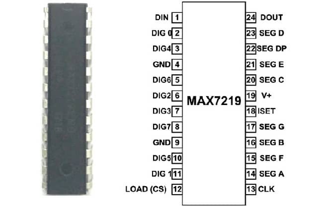
The MAX7219/MAX7221 drivers feature a serial input/output configuration and are commonly used in applications where a common-cathode display is required. These drivers offer several integrated functionalities, including a BCD code-B decoder, multiplex scan circuitry, segment and digit drivers, as well as an 8x8 static RAM capable of storing data for each digit. Whether you are working on a project that involves numeric displays, bar-graph displays, or individual LEDs, the MAX7219/MAX7221 drivers provide a reliable and efficient solution for interfacing with microprocessors.
Circuit Diagram & Connections
Below is the circuit diagram for Stopwatch Using 4 Digit 7 Segment Display & Arduino. Assemble the circuit as shown in the figure below.
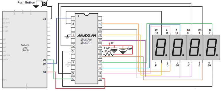
Pin D7 is connected to DataIn (DIN) of MAX7219
Pin D8 is connected to CLK (CLK) of MAX7219
Pin D9 is connected to LOAD (CS) of MAX7219
The 4 Digit 7 Segment Display used here is the Common Anode type. You can even use the Common Cathode type and reverse the Supply and GND.
Working & Operations
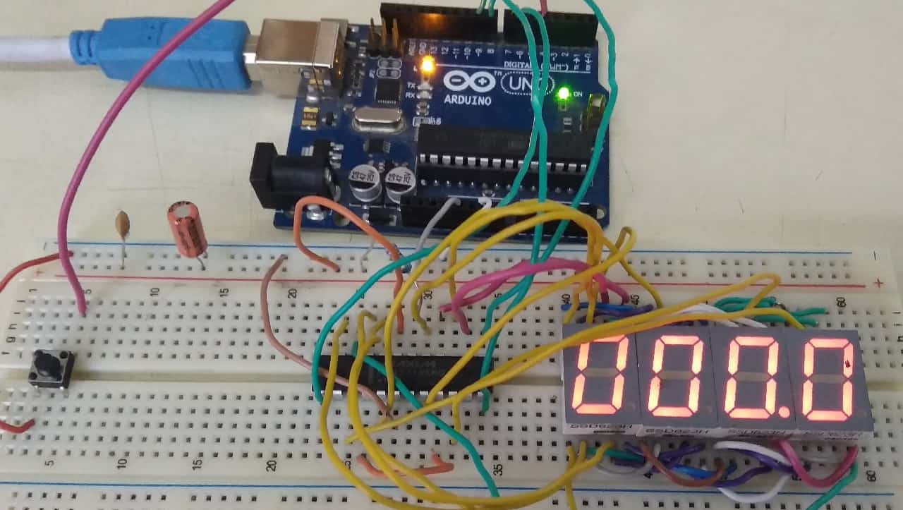
Once the code is uploaded to Arduino Board, it will display 000.0. So just press the start button and then the time elapsing starts. To stop the time elapsed just press the same button again. Hence the stopwatch will stop. Now if you want to reset the circuit, then simply press the reset button of the Arduino UNO Board.
The stopwatch can be used to measure up to 999.9 seconds.
Source Code/Program:
The Source Code for Lap Timer/Stopwatch for above circuit is given below. Simply upload the code to Arduino Board. But before that you need to add these two libraries below:
1. LED Control Library: Download
2. Bounce2 Library: Download
#include <LedControl.h> // Library for LED control with MAX72XX
#include <Bounce2.h> // Library for Bounce of switches

/*
Pins of Arduino Nano for LedControl:
Pin #7 is connected to DataIn (DIN)
Pin #8 is connected to CLK (CLK)
Pin #9 is connected to LOAD (CS)
There is only one display with MAX72XX
*/

LedControl lc = LedControl(7, 8, 9, 1); // LedControl(dataPin, clkPin, csPin, numDevices)

int k, lastTime, diffTime;
int a, b, c, d;
int a1, b1, c1, d1;

int pinStartStop = 4; // Start-Stop Pin

bool statusSwitch1 = false;

Bounce SW1 = Bounce(); // Define Bounce to read StartStop switch
Bounce SW2 = Bounce(); // Define Bounce to read Lap switch

void setup() {

pinMode (pinStartStop, INPUT_PULLUP);

// After setting up the button, setup the Bounce instance
SW1.attach(pinStartStop); // Sets the pin (Internal Pull-Up)...
Read more »
 Hulk
Hulk