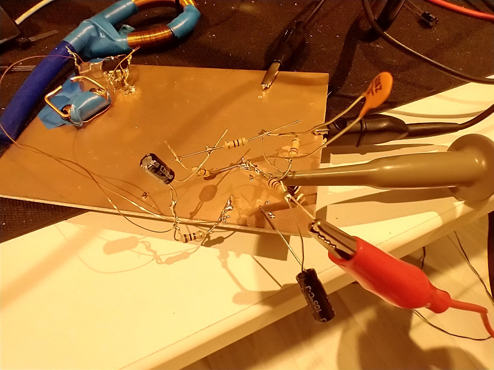
Rogowski coils are a popular type of current sensor used for power electronics development. Wikipedia has a good introduction to them: https://en.m.wikipedia.org/wiki/Rogowski_coil . If you fancy getting a good one then PEM https://www.pemuk.com/ will happily take £1000 off you and give you a calibrated, 50MHz, lots of amps coil. Some of the big players (eg Keysight) will rebrand the PEM ones so they're clearly good bits of kit.
I, however, cannot justify getting one of those. I do get to play with them at work but that's not useful in my home lab.
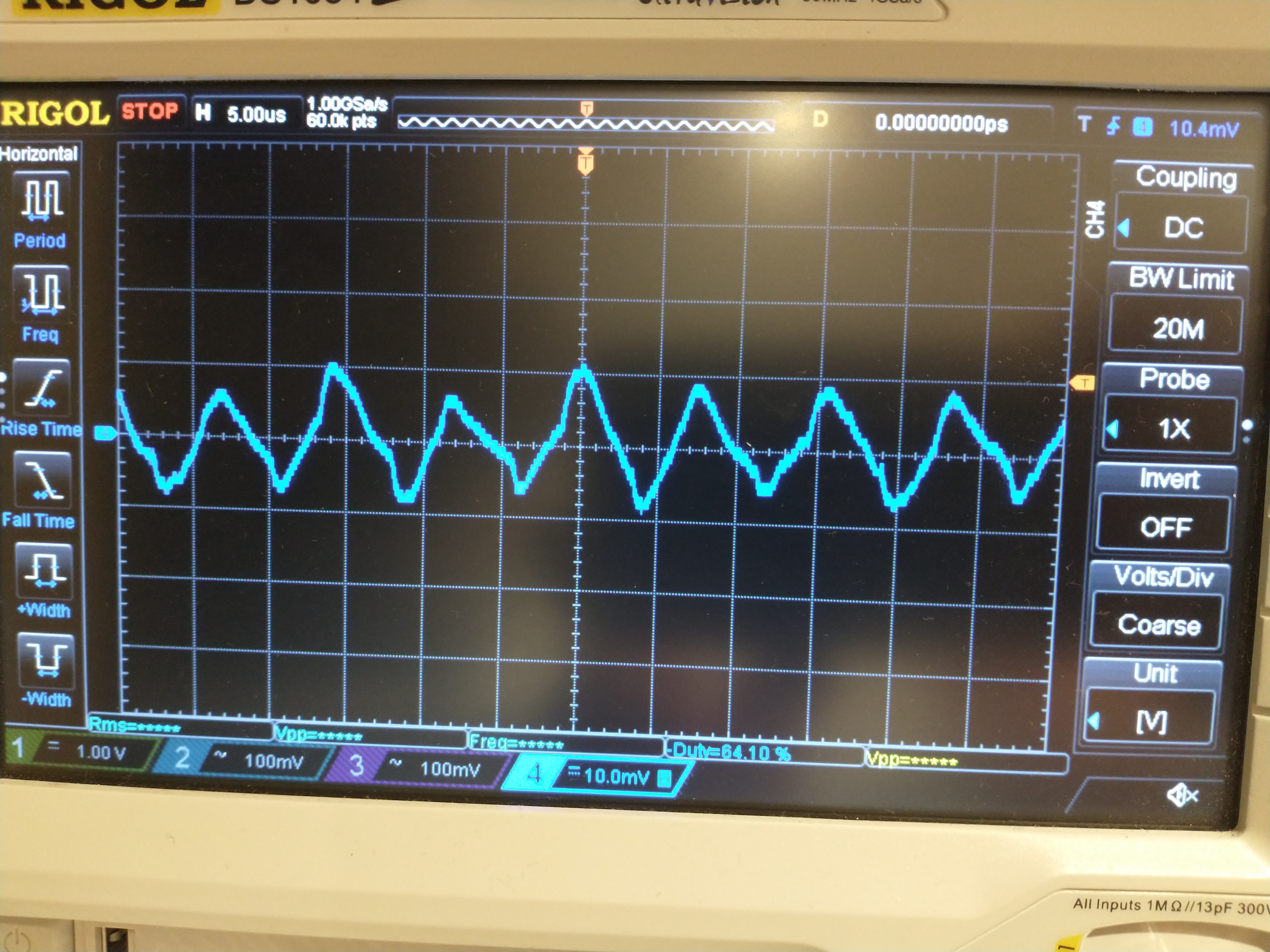
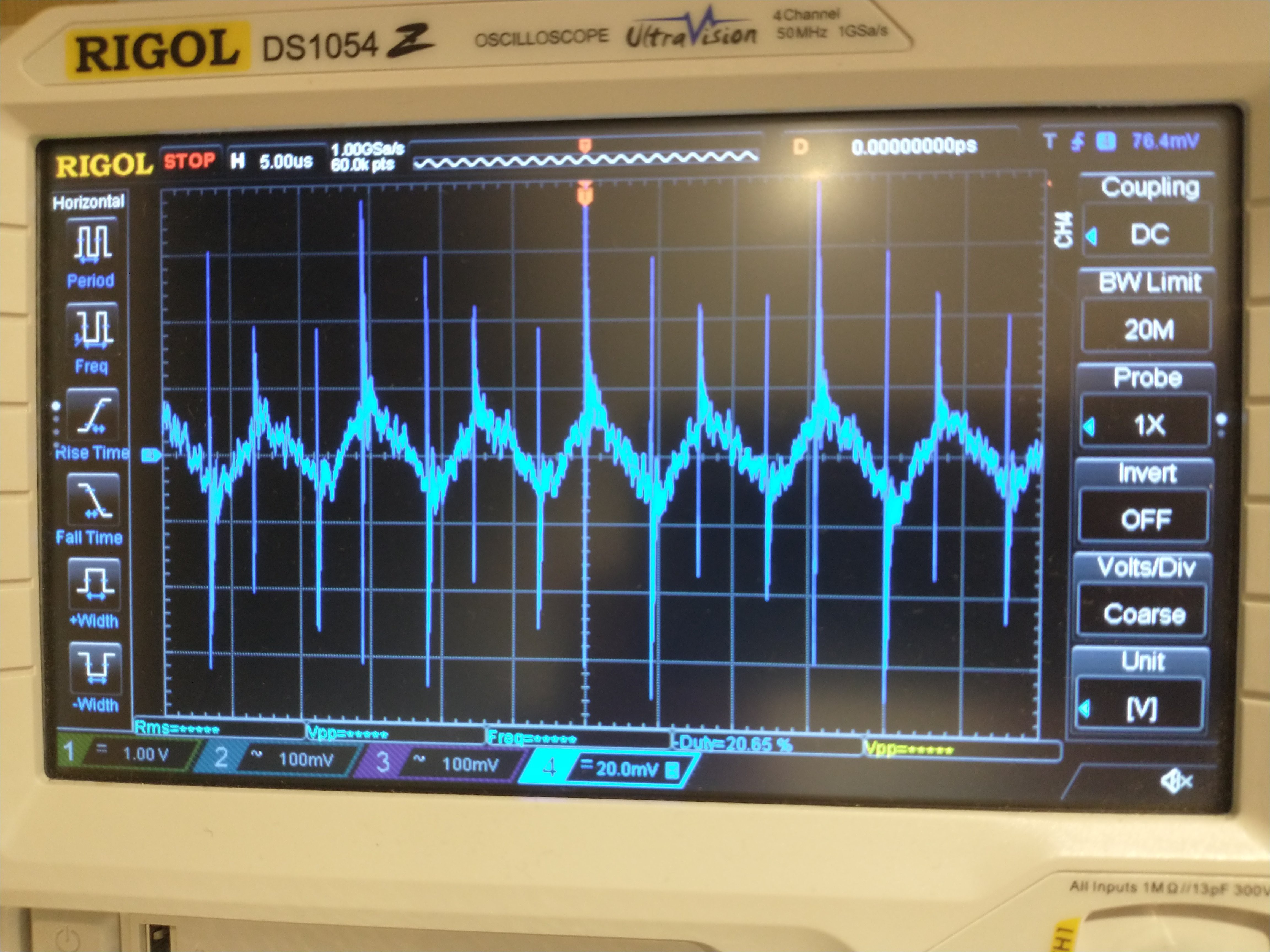
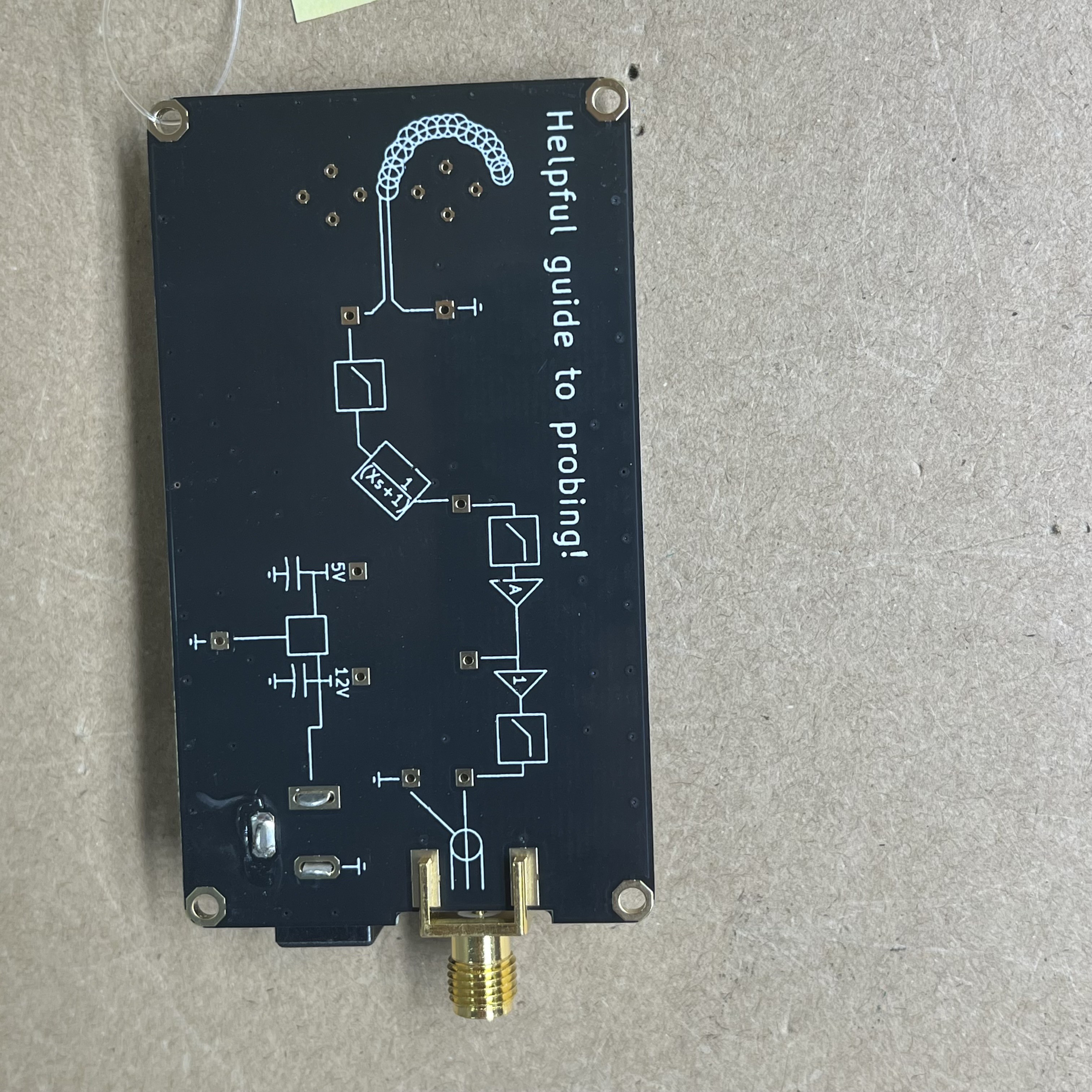
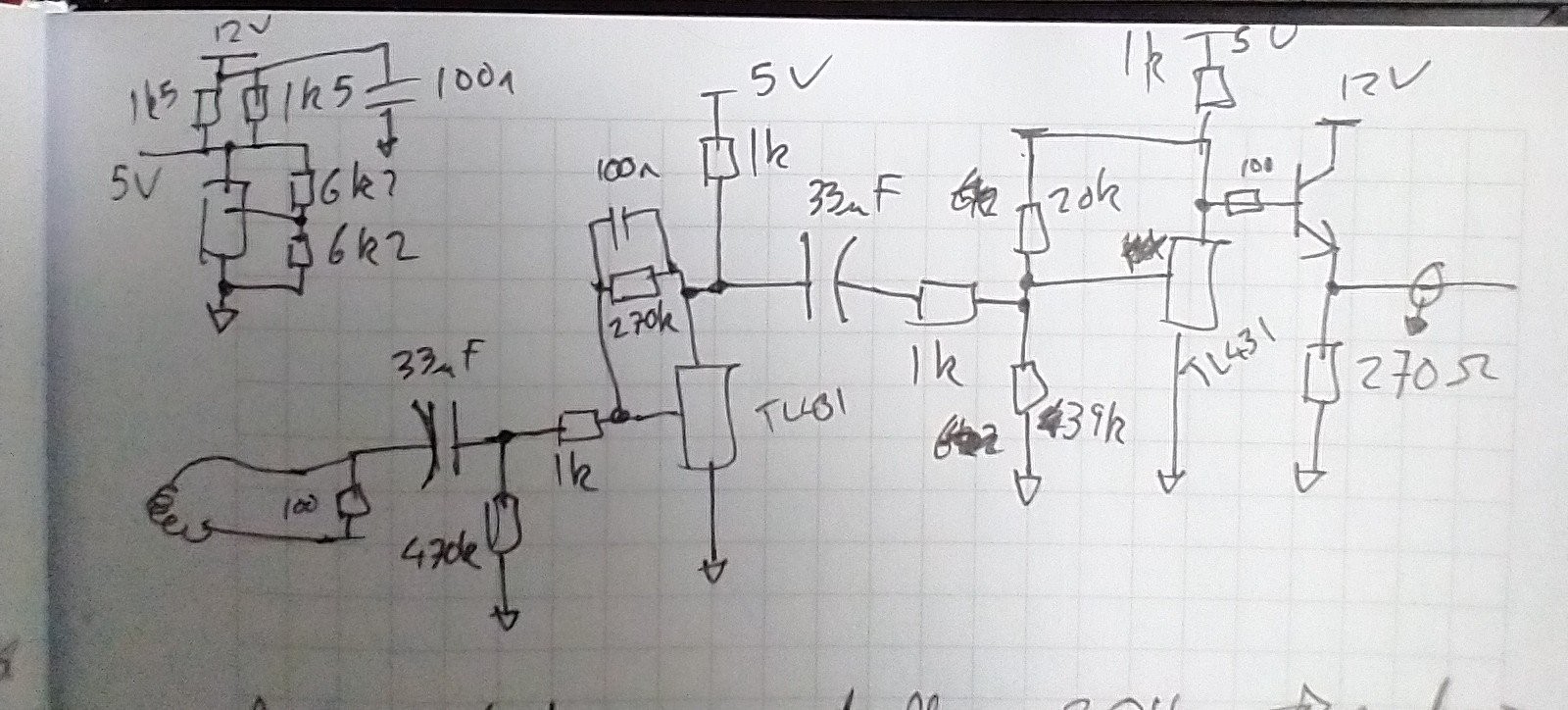
The coil responds to the rate of change of current (di/dt). In order to get the current, we need to integrate this. Usually, we would use an opamp as an integrator. it just takes a couple of resistors and a capacitor. We need to be careful of the DC offsets (voltage and current), bandwidth and design the coil carefully. As analogue integrators are not perfect we can have to have a minimum frequency otherwise the integrator will windup and crash into the rails.
I've made a couple of coils before with fast, low offset opamps so this project felt like it needed something a bit different.
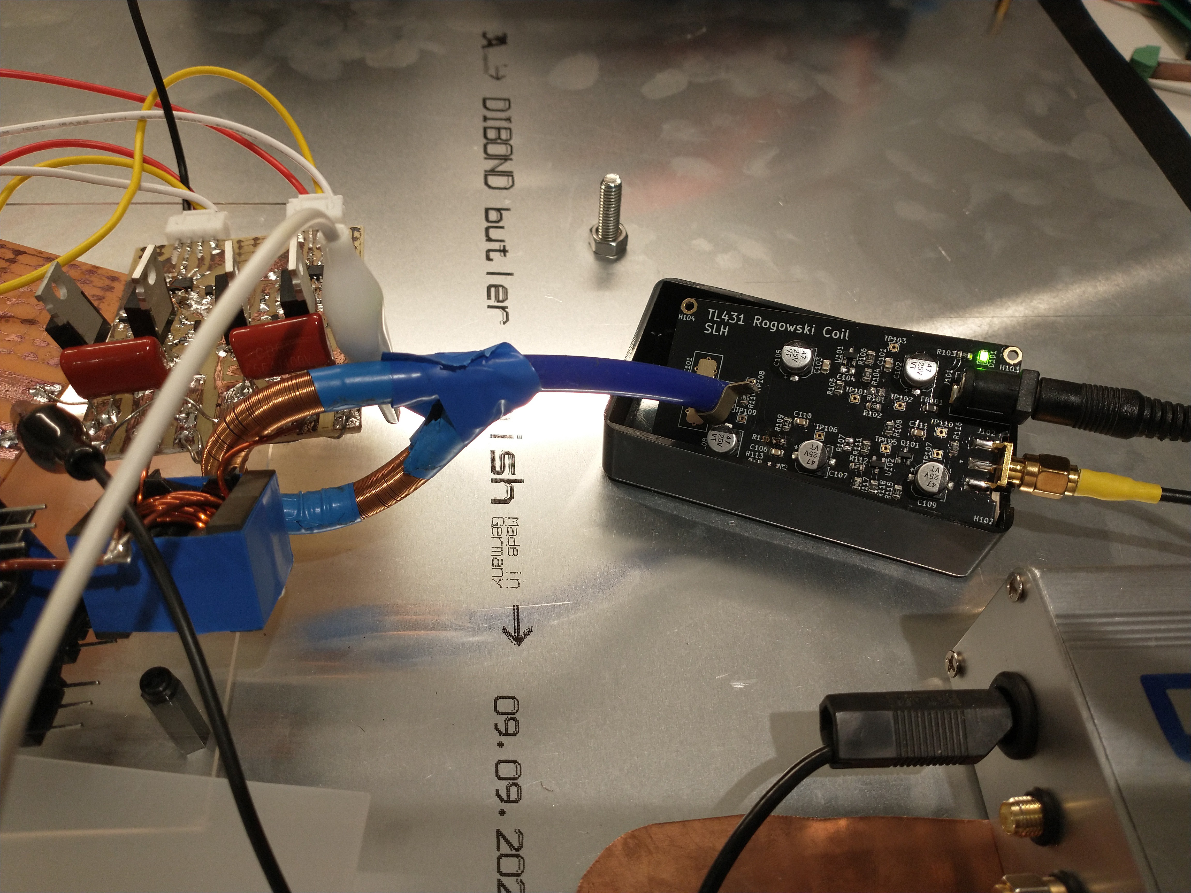
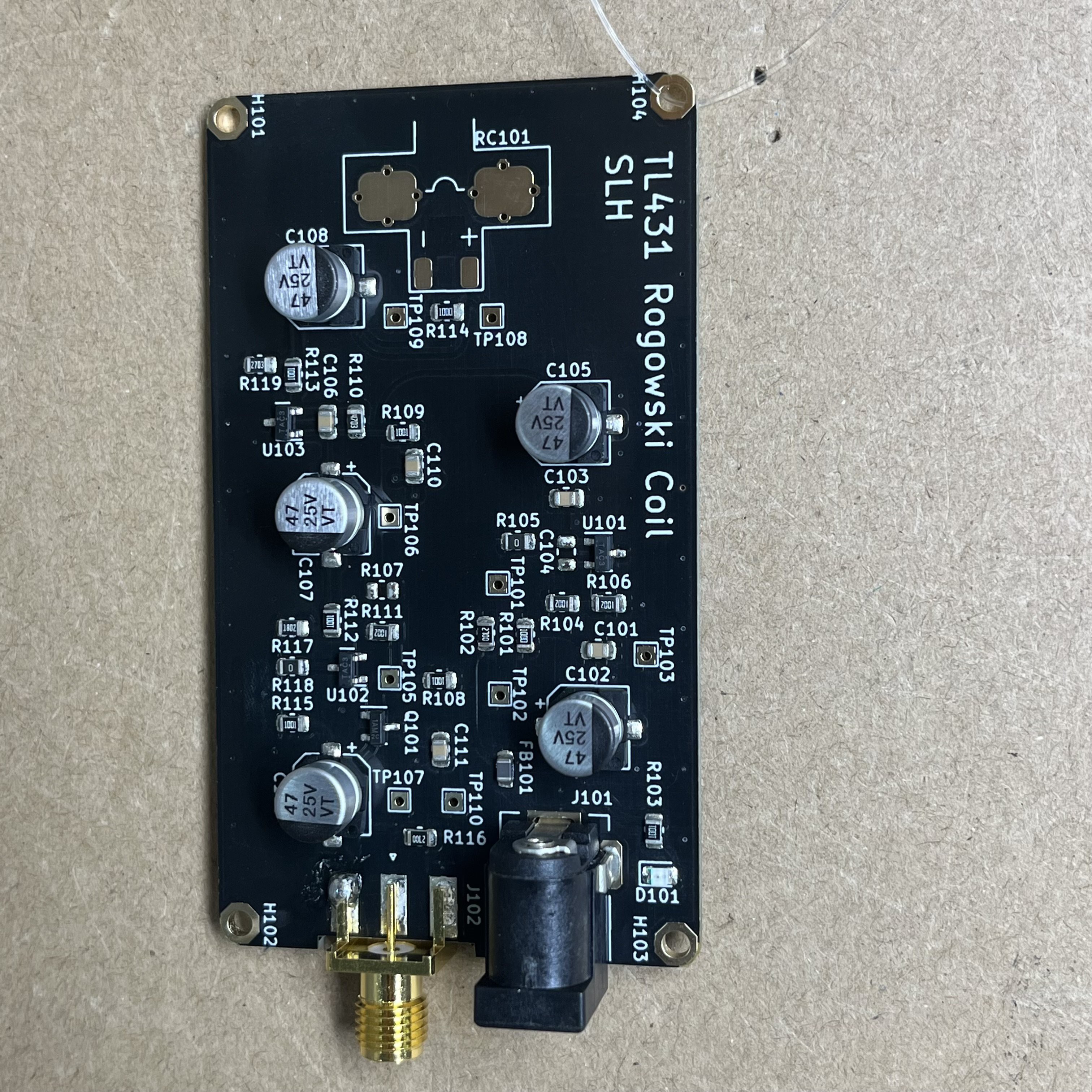
For this project I decided to abuse some TL431 shunt regulators. TL431 regulators have a pretty good bandwidth, a fixed reference on the positive terminal and most importantly are cheap and readily available. I have a bag of them of dubious origin...
 DeepSOIC
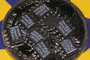
 Richard Dudley
 Jarrett
 Yann Guidon / YGDES