 Dan Julio
Backstory
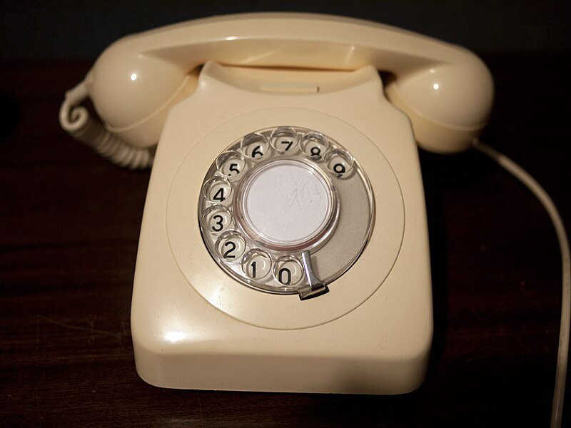
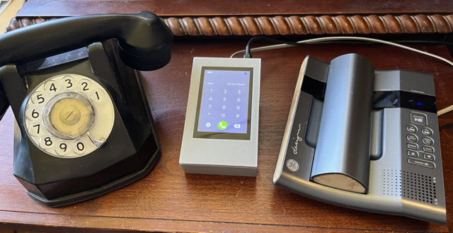
In 2019 I made a gadget called Blue POT that let us use an old 1945 rotary telephone we had with our cellphones.
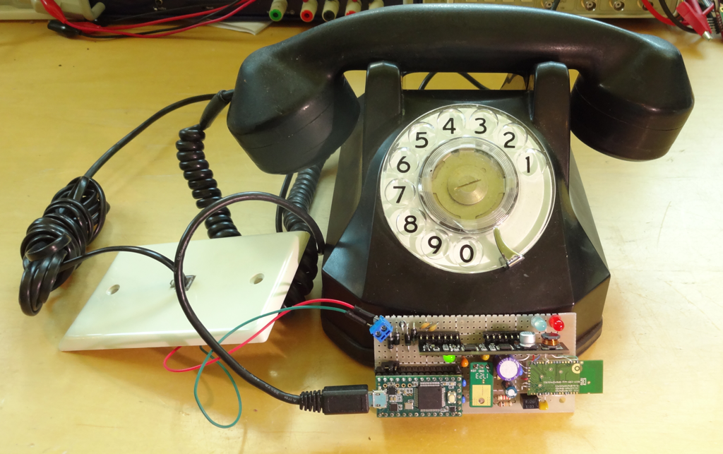
It was fun but suffered from some issues. Audio levels weren't great, there was noise and configuring the BM64 bluetooth module was a huge pain. I always wanted to revisit this project because I find old telephones and their history to be very fun and interesting. Finally this year with the completion of my own development board I decided to revisit my old telephone project. However this time I decided to make a more general purpose gadget - weeBell.
The name weeBell is a play on both small and wireless and pays homage to the granddaddy of all technology companies, AT&T or simply "Ma Bell". In 1984 AT&T's telephone system was split into several regional telephone companies or Baby Bells as they were christened. weeBell is an even smaller regional telephone provider...a provider for one.

(back when talking on the phone was glamorous)
Start of the project
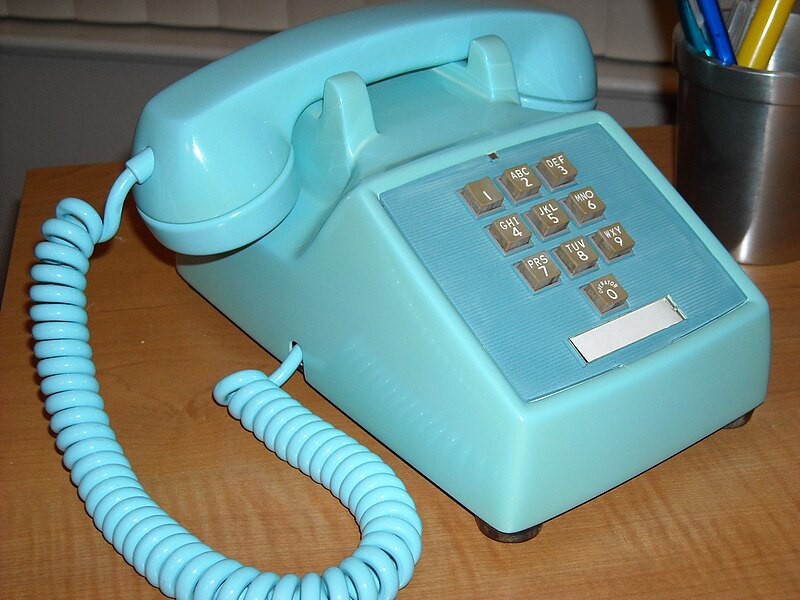
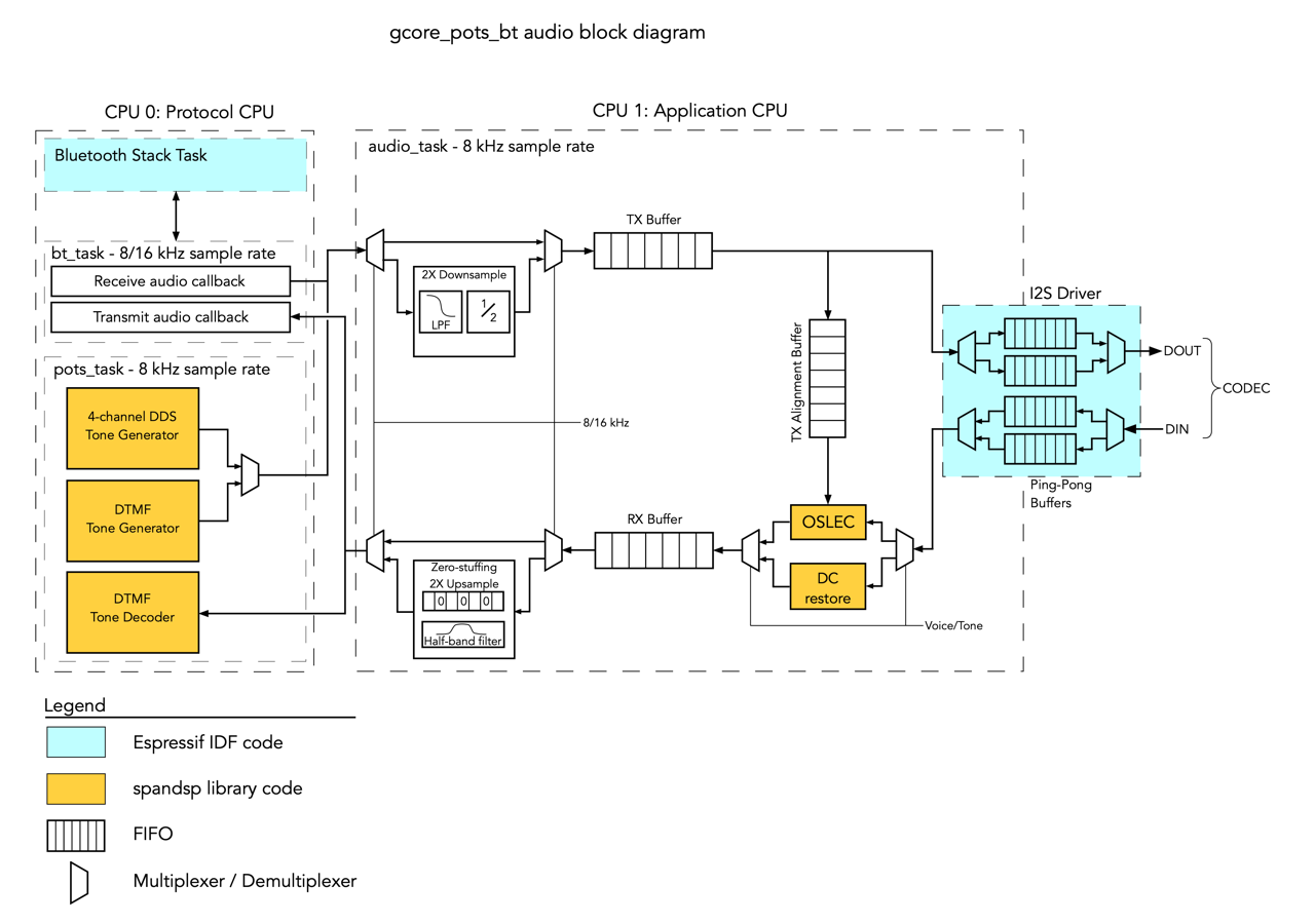
The ESP32 is a tremendously capable chip. With two processors it can take on a lot of real-time processing tasks and the Espressif IDF provides support for classic Bluetooth handsfree profile as well as SIP telephony. I'm sure Espressif intends this stuff to be used in little "Alexa" like speaker gadgets but I figured it could also be used with the SLIC module I originally used to talk to POTS phones. This meant I could make a device that could be used for a variety of end uses.
- Using POTS telephone to place and answer calls through a cellphone
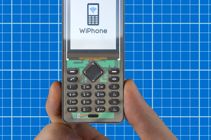
- Implementing a VOIP phone using the SIP protocol to talk to asterisk or other SIP providers
- Creating a Museum or Art installation controller that lets people interact with (and perhaps store) messages stored on a Micro-SD card from a phone. Different messages could be reached by dialing different numbers. Or maybe messages could be left for others to discover (lol, maybe this wouldn't be a good idea for the general public...)
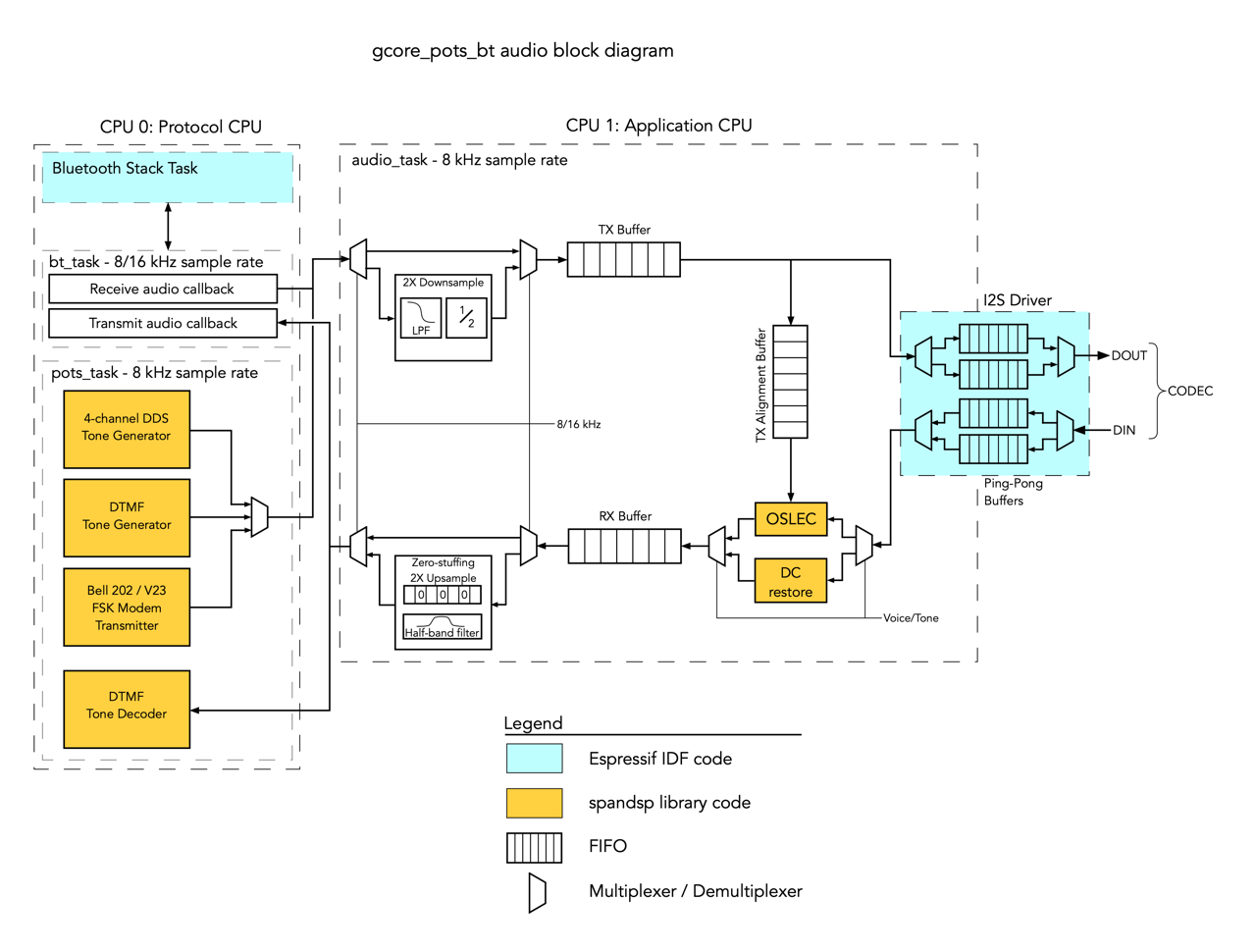
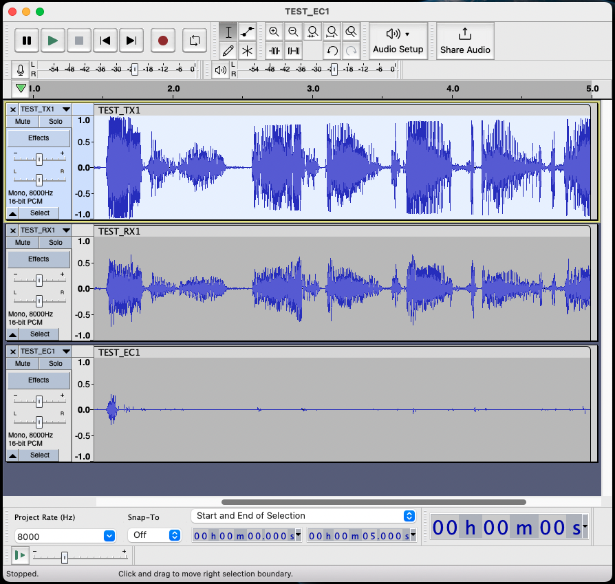
I started with the bluetooth implementation. It took me weeks of effort to understand how I could reproduce my original gadget because I had to learn about the Espressif Classic Bluetooth library (with detours to Bluekitchen's BTstack and Espressif's ADF and back), and figure out how to deal with things like echo cancellation (thankfully I could stand on the shoulders of some real experts, like Dave Rowe and Steve Underwood, who shared their telephony code).
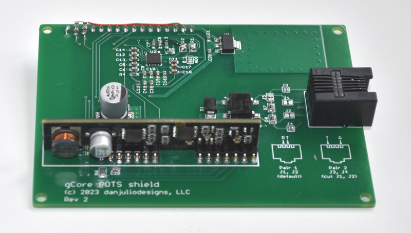
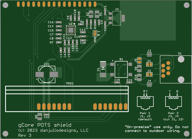
gCore's first shield
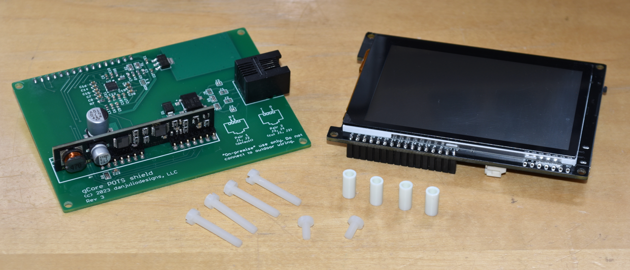
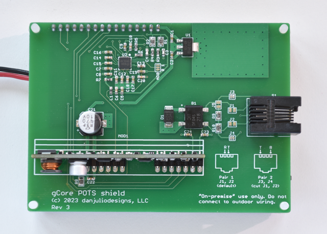
Finally I had a rough prototype running and could design a new PCB to hold the telephony components.
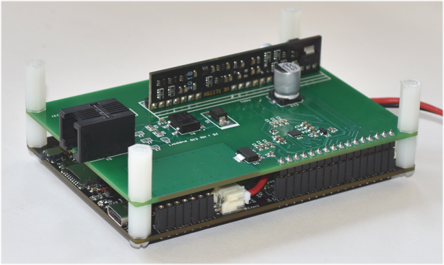

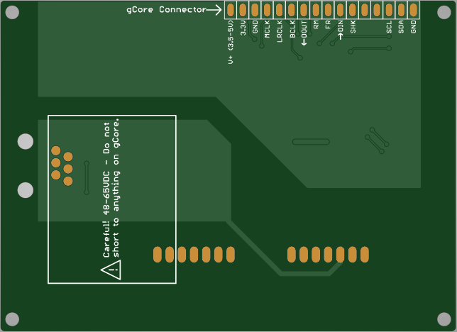
I started with the NXP SGTL5000 Codec chip, mainly because I had one laying around on a PJRC Audio shield. The hybrid function is once again provided by the Silvertel AG1171 SLIC module. It adapts the audio to and from the codec to the telephone line, generates ringing voltages and can detect hook actions (used to determine off-hook condition and rotary dialing). I briefly thought about trying to design my own analog circuitry because the AG1171 had gotten a lot more expensive but quickly realized best to leave this to the professionals. There is some additional protection circuitry since the AG1171 is specified to drive up to 1 km of wiring. But that wiring is meant to be "on-premise", meaning within one building. It can handle typical induced spike voltages but can't handle a lightening strike like telephone company line cards could. What is neat about this is that you can connect weeBell to the existing wiring in a building (disconnecting it outside the building!!!) and then plug up to three POTS phones into other outlets on the same circuit.
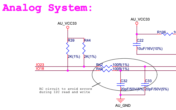
Here's the output circuitry on the initial revision of the PCB.
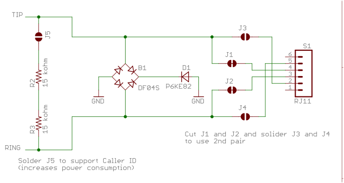
The bridge rectifier and ESD suppressor shunt excess voltages to ground. The resistors allow the AG1171...
Read more »


 stupid
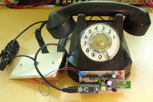

 ziggurat29
 Dan Fay
Currently I have an old Panasonic pbx system (KX-TA624) in the house with 6 rotary phones in various rooms as a "intercom" system (ie, internal extensions, no ext line out). Wondering if you plan to allow ganging together of your shield to accommodate more than 3 extensions? Also, if you want to incorporate some of the standard panasonic pbx functionality, i'm happy to provide whatever info I might have about the system as you develop things. I would love it if I could connect my cell via bluetooth to your shield and dial POTS extensions from my cell! That would be a cool extension...