 OzQube
I've started designing a prototype board.
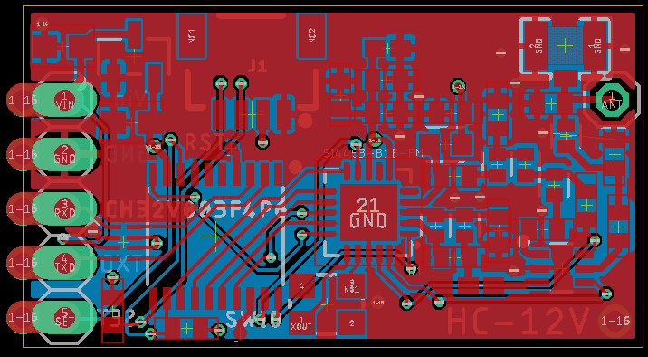
The original HC-12 is 14.4mm x 27.4mm. It appears to be a 0.8mm thick PCB.
To fit in the QWIIC connector, I've increased the size slightly to 16x29mm.
There's work to do to standardise the 0402 footprints. The various Eagle libraries I used have different pad sizes, depending on whether it's an inductor or capacitor.
I've designed around using the OSH Park 4 layer PCB. A quick search online lists the recommended trace width and spacing for 50 Ohms. Once I refine it for a 0.8mm PCB, these settings will change.
I also need to make a custom footprint for the castellated edges. My spacing isn't right and it breaches the design rules if I move the pin header row any closer to the edge of the board.
The actual values of the components on the REF side aren't known exactly. I've used the schematic from the Silabs App Note AN648 . It lists calculated values for Class-E Switched TX/RX Board Configuration, but only for 390Mhz and 460Mhz. As 433Mhz is approximately halfway between these, I'll guesstimate the values that should be selected, based on the nearest standard value that is the midpoint of the values listed in the App Note.
Another thought is to increase the size of the input capacitor for the LDO. Most applications have recommended putting a larger capacitor on the Vin line, so if I can shuffle things around to fit in something larger, I will.
I'm also tempted to increase the board size slightly to have an actual pin header for programming. Otherwise, I'll just have to solder wires to the test pads.
Discussions
Become a Hackaday.io Member
Create an account to leave a comment. Already have an account? Log In.