 M. Bindhammer
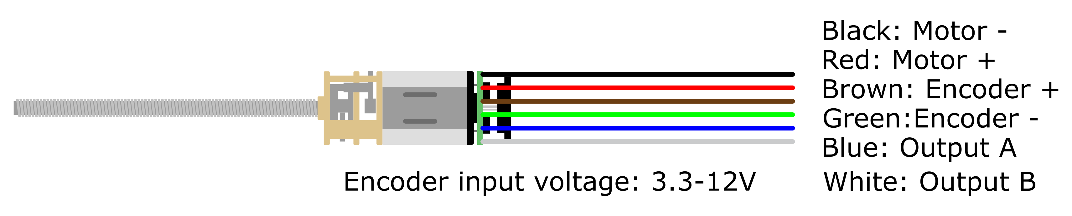
It took me a while to figure out the wiring of the encoder PCB. It is as follows:
After soldering pin headers to the motor wires, the rotary encoder was tested with an Arduino Mega.
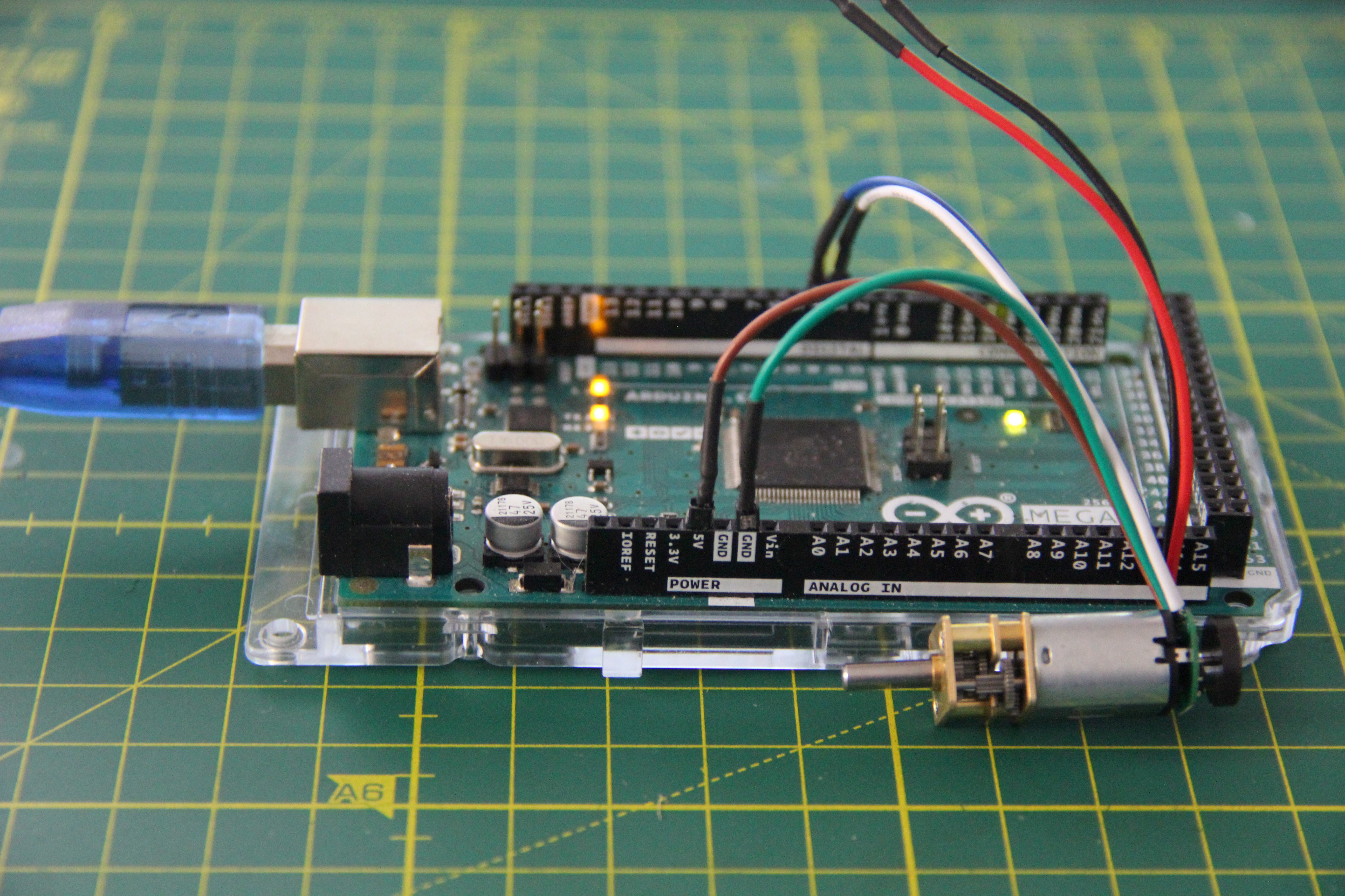
I took the test code from the Arduino project hub.
int counter=0;
String dir="";
unsigned long last_run=0;


void  setup() {
  Serial.begin(9600);
  attachInterrupt(digitalPinToInterrupt(3),  shaft_moved, FALLING);
  pinMode(4,INPUT);
}

void shaft_moved(){
  if (millis()-last_run>5){
    if (digitalRead(4)==1){
      counter++;
      dir="CW";
      }
    if (digitalRead(4)==0){
      counter--;
      dir="CCW";}
    last_run=millis();
  }
}

void loop()  {
  Serial.print("counter : ");
  Serial.print(counter);
  Serial.print("  direction : ");
  Serial.println(dir);
}
The rotary encoder has a resolution of six counts per revolution of the motor shaft. A motor driver with a break function is certainly required, plus PID control.
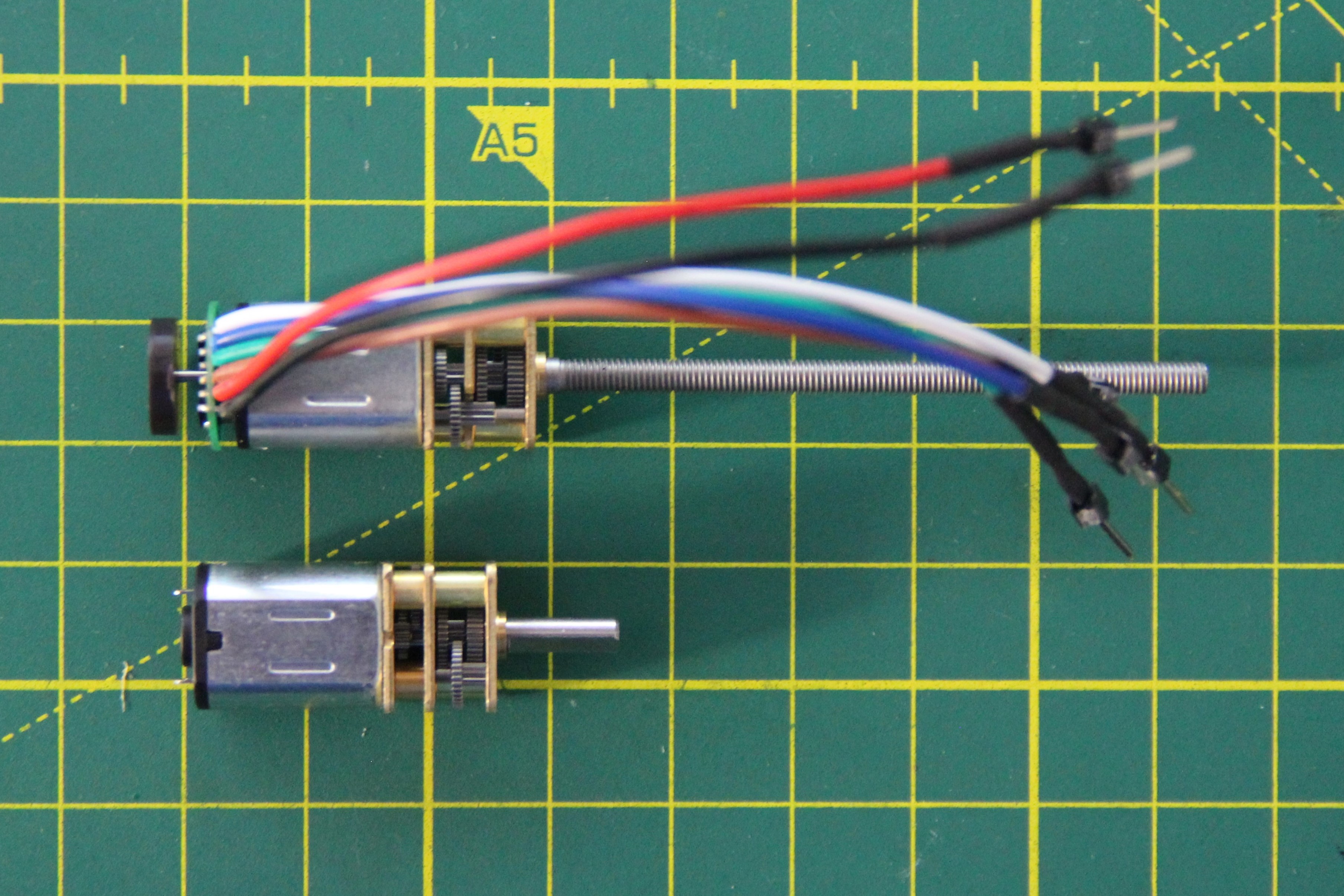
Finally, I changed the motors, which is absolutely no problem. For this, only two screws have to be loosened with a small Phillips screwdriver.
Discussions
Become a Hackaday.io Member
Create an account to leave a comment. Already have an account? Log In.