Close
0%
0%

DIY Mat Board Cutter CNC Head

A mostly printed DIY CNC Head for cutting mat boards for picture framing.

Similar projects worth following
I've always wanted to be able to make those cool fancy mat boards that they charge an arm and a leg for in the picture framing store. You know the ones with layered mat boards that create picture boarders that beautiful but complex. I especially like the ones that have a v-groove line created with partial depth cuts leaving a detailed scroll work in a contrasting color (using dual color mat boards). Hand cutting the mat boards with manual razor blade guides is very difficult for anything except simple rectangular cuts, so for many years I have wanted to build a mat board cutting head for one of my CNC machines. Over the years I've designed several different versions of a cutting head, but all of them have been very complicated and hard to manufacture, but with a 3D printer I feel that I can finally make one that should work.

Design goals:

• Simple to build
• Inexpensive
• Small as possible
• Needs to be able to make precise

For this iteration 3D printing should help me meet the first to goals, and I think that this design is small enough to be useful even though goals one and three are usually mutually exclusive. To be able to achieve the last goal I’ve decided to make the whole head float up and down on linear rails and be pressed against the mat board with a spring. The head will glide over the surface of the mat board on a PTFE pressing ring that will provide a consistent “zero” reference to the top of the mat board. This design allows the knife blade tip to be located at  X, Y ,Z zero at the center of the presser ring at the top of the mat board while the ring is riding over the surface of the mat board.

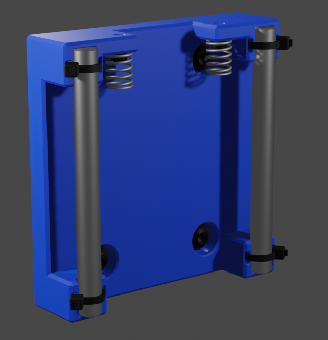
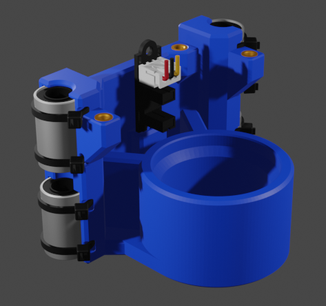
I will have to experimentally determine how much spring force is required to keep the ring pressed against the mat board while the knife is being plunged into it. To aid in this the current design allows 3mm of over travel after the ring touches the mat board. Of course that amount can be adjusted by reprinting the mount plate and using slightly longer linear rails.

The blade plunges into the mat board at a 45 degree angle by using a stepper driven lead screw to force a driver down on a slider that is guided down at the required angle.


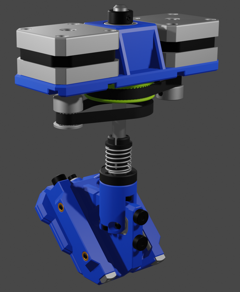
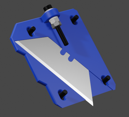
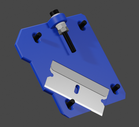
The slider and driver interfaces are through V623ZZ V-Groove bearing riding on hardened 5mm shoulder screws that can be inserted and removed for assembly and disassembly. The slop in these linear rails can be adjusted with grub screws that push the shoulder screws into the fixed position V-Groove bearings.

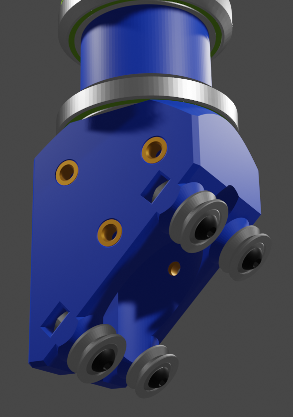
In order to place the bearings as accurately as possible I cannot use brass threaded thermal inserts (which I prefer for 3D printed parts that will be assembled and disassembled multiple times) I will instead leverage the accuracy of the 3D printer to place slightly undersized holes for the bearings. I can then mount the bearing with screws through the printed holes into nuts.The blade is clamped to the slider with a plate that can be customized for different blade types. I've designed up versions for a Utility Knife blade and a Single Edge Razor Blade.

The clamping plate can be fine adjusted with a screw that moves it up and down slider.

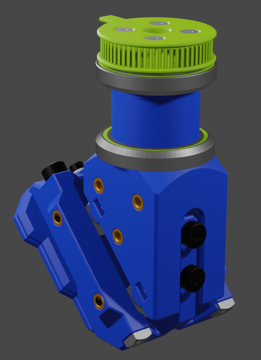
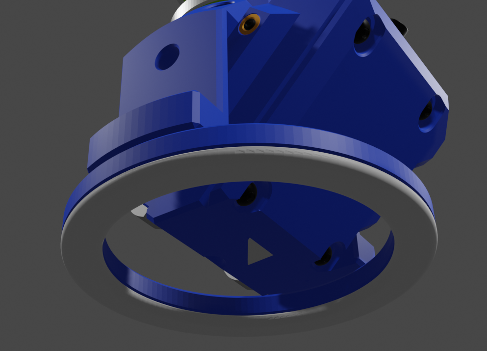
The knife will be pivoted around the vertical using a stepper motor and bicycle headset bearings that seat into tapers.
Both the GT2 pulleys for the lead screw and the knife pivot have flags on them to trip the optical limit switch mounted to the pivot bearing block. With two flags and only one switch some care will be required to "home" the head, but should be doable. Also the design necessitates that in order to maintain a consistent depth while pivoting the knife the lead screw will have to be rotated in sync with the knife pivot. This is fairly simple with both the lead screw and pivot GT2 pulleys arrangements being the same size. Using 20 tooth pulleys on the stepper motors and 60 tooth pulleys on the lead screw and pivot gives a 3:1 "gear" ratio that results in 0.3 degree pivot resolution and 0.007mm depth resolution with half stepping.

  • Animating the Plunge

    wooddragon4805/17/2023 at 01:26 0 comments

    This is my first animation, it shows how the slider would plunge into the mat board. The slider plunges down the max travel of 6mm.

    More animations to come.

  • Interference

    wooddragon4805/16/2023 at 03:15 0 comments

    Well no assembly animations yet, but in my endeavors to create one I discovered that it wasn't possible to assemble the Slider Driver on to the Slider because of an interference that prevents you from inserting a bearing axle screw. The fix is almost trivial but required slightly longer shoulder screw. While I was checking the lengths that I could get I was also looking at the cost of the screws, and decided that $4-$6 per screw was not really ideal. This lead me to redesign the slider to use 5mm rods instead of the shoulder screws.
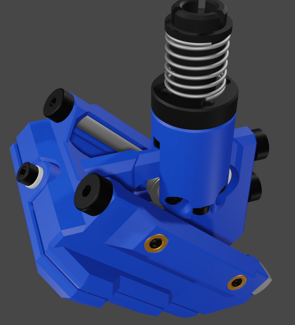
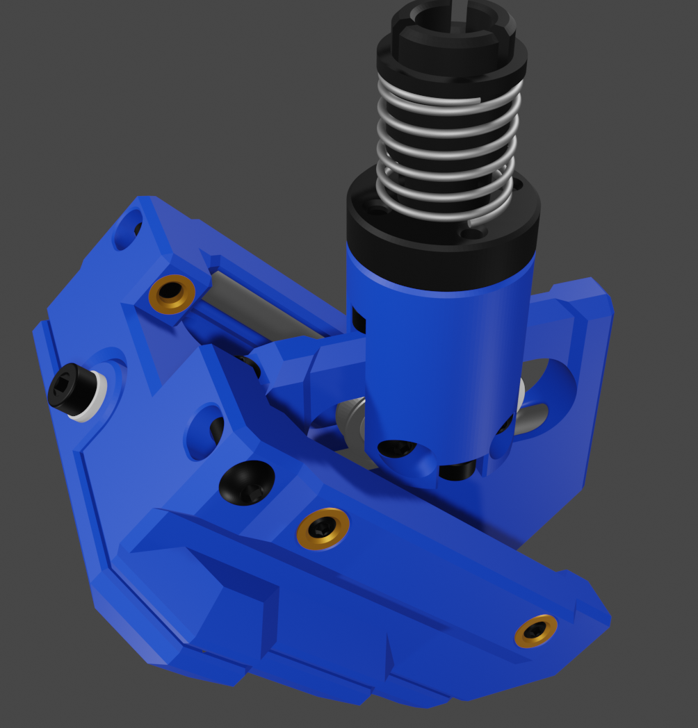
    The new design uses M3 keeper screws that prevent the 5mm rods from working out of the Slider block. To allow for disassembly the keeper screw can be removed and the rods pushed out via the 3mm through holes at the end of the rail slots.
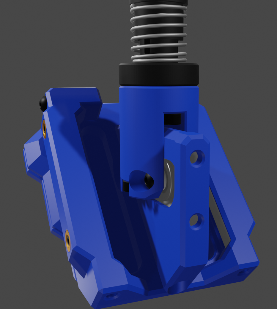
    Hopefully I will now be able to make an assembly animation.

  • FreeCAD and Blender

    wooddragon4805/15/2023 at 01:17 0 comments

    Of course this project has been designed in FreeCAD, but I'm still having fun with Blender so the pretty pictures for this project are from a Blender import from FreeCAD. I'm currently trying my hand a creating some animations, so some time soon I should post some assembly animations.

View all 3 project logs

Enjoy this project?

Share

Discussions

wooddragon48 wrote 05/31/2023 at 02:16 point

Well I suppose that you could move the X,Y,Z axes simultaneously and achieve a plunge at a 45 degree angle to match the blade angle. That would require a much more complicated algorithm to calculate the knife path, as the X and Y coordinates on the surface of the board would (where the zero depth would be) would be a function of the plunge depth and the rotation angle of the knife holder. I will think about that, and do some calculations/simulations to see how difficult it would be to process a cut path for that kind of operation. My original idea was to create a plug in for Inkscape to output the required g-code, this would just make that a lot more interesting to code. Thanks... you have sparked off a very interesting idea.

  Are you sure? yes | no

wooddragon48 wrote 05/31/2023 at 02:39 point

On further thought I can see two down slides to this approach. First, the head would have to be zeroed on the surface of each mat board instead of just when the blade is changed. Second I'm not sure how to compensate for the varying thickness of the mat board. Granted this is probably only an issue when cutting partial depth V-groove accents, but that is also one of the things I am designing this to do. This is akin to the issues with milling pcboards, and doing a full surface mapping of the mat board seems impractical.

  Are you sure? yes | no

Krzysztof wrote 06/01/2023 at 07:58 point

Don't you need to zero this for each different board? As for math - there is already gcode (G40-G42) for cutter offset. If you have inkscape - simple line offset should be enough (but I may be wrong, those offsets probably don't include angle-related problems).

> I can see two down slides to this approach.

:). Yeah, on second thought your mechanical contraption is a VERY nice solution to all that math problems.

  Are you sure? yes | no

Krzysztof wrote 05/30/2023 at 07:52 point

Is that plunging mechanism really required? It's VERY impressive, but complicates whole design a lot, while you could do that in software (unless you don't have z axis?).

  Are you sure? yes | no

wooddragon48 wrote 05/31/2023 at 02:27 point

See the above ramblings.

  Are you sure? yes | no

Similar Projects

Does this project spark your interest?

Become a member to follow this project and never miss any updates