Development and repair of switching mode power supplies , battery charger, motor drives and many others required use of oscilloscope with isolated channels. Unfortunately those oscilloscopes are relatedly expensive even if you buy an used one like TPS2xxx series. The TPS2012 can be found on ebay for about $1500 and having on mind that this is only 2 channel 100 Mhz bandwidth scope the purchase make no sense except for people that need scope with isolated channels on daily base but can't afford a new one.
For people like me that do not use it on daily basis, and already have other scopes, buying such a scope is not the best option, and here the Tek A6909 come in to the game. This is relatively old Sony-Tektronix isolation amplifier produces in two configurations, A6909 - 2 channels and A6907 - 4 channels.
The amplifier is well designed and fully repairable, no custom or potted parts with available service and repair manual /can be found on the link/
Those amplifier has two issues, first is the non standard probe connection, the same used in the old portable Tek 2xx scopes. Find such a probe is a challenge, and the easiest solution is to reworked it for a standard 10x probe. The second problem is the leaking electrolytes. I both 2 A6909 amplifiers, and all 4 channels had this issue, so most probably you will need to replace them even the unit seems working.
The probe connection rework is relatively simple task. On the 2 channel model both input and output BNC connectors can be installed on the front panel, on the 4 channel model the output connectors should be kept on the back of the unit.
When replacing the connectors keep on mind that this is isolation amplifier, so you should provide a reliable isolation from the enclosure, and between the channels themselves. Fortunately the front panel is design around isolation, and the rework is very simple. There is small half flange around the connector that need to be removed to allow proper installation of a standard BNC connector.
I used a Molex 0731315013 insulated BNC connector soldered to a small prototype board. The purpose of the board is not so much to take the resistor and the trimer but to provide a reliable attachment for the coaxial cable. Keep on mind that the original cable is with very thin central wire that can be broken very easy.
Since the amplifier impedance is 333.3 kOhm the original probes are with 9.66 Mohm internal resistance and for a proper operation a 666 kOhm resistor need to be add in series to the probe. Hawing on mind that a full calibration will be required anyway the value of the resistor is not so important until is in available for the adjustment range. In my first version i used 1 Mohm resistor, and planing to change it with a selected 665kOhm 1%. The 1% tolerance giving you +/- 6.6 Kohm and there is a good chance to find easy one that is close to the 666.66 kOhm required. A parallel capacitor is required to compensate properly the added resistor. With 1 MOhm resistor a 11-12 pF capacitor is OK, but the best option is to add a 5-30 pF trimmer capacitor.
Here are the resistor Vishay RN55D6653FRE6 and the trimmer capacitor Knowles Voltronics JR300 i did order.
To fix the leaking capacitors you will need the following values :
82 uF /35 V Nichicon UPJ1V820MED1TD, 3 pcs per channel on A10 board
22 uF / 35 V Nichicon UPJ1V220MDD1TD, 2 pcs per channel on A10 board
22 uF / 25 V Nichicon UPW1E220MDD, 1 pcs per channel on A10 board
10 uF / 25 V Nichicon UEP1E100MDD, Non Polar 1 pcs per channel on A10 board
10 uF / 16V Nichicon UPS1C100MDD1TD, 4 pcs for A6909 and 8 pcs for A6907 on A30 board
220 uF / 25 V Nichicon UPW1E221MPD1TD , 6 pcs for A6909 and 12 pcs for A6907 on A30 board
47 uF / 16 V SMD tantalum Vishay TMCHC1C476MTRF , 2 pcs for channel on A20 board
220 uF / 35V SMD Nichicon UWT1V220MCL1GB, 2 pcs for channel on A20 board, plus 2pcs on A50 board....
Read more »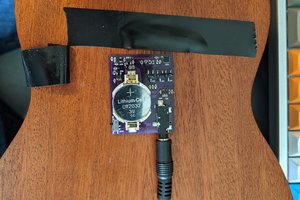
 Arno
Arno
 helge
helge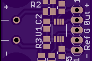
 Christoph
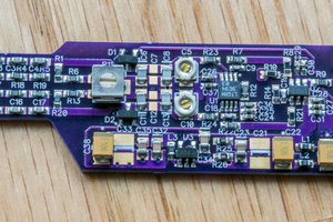
 Bud Bennett