OK so I'm following the four stages that I logged earlier today - Stage 1 is the Power Supply.
This project uses batteries for all its power supplies, avoiding the danger of electric shock that exists with mains-based high voltage power supplies. Battery valves use lower voltages (potentially down to 12 volts or even lower), and they allow me to use breadboard type construction. Breadboard construction is easy to do and looks really good with the radio valves. Breadboard construction isn't suited for mains-powered valve projects as there's no protection against casual contact with high voltages.
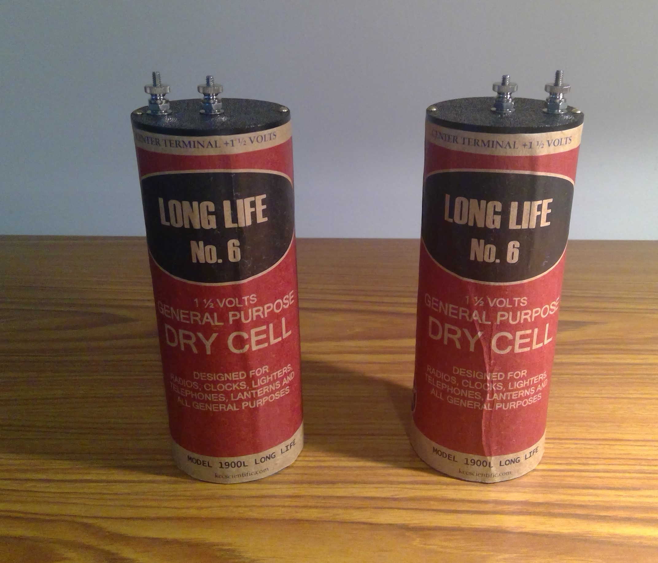
So, here is the LT (low tension) supply for the valve filaments. I bought these monsters a while ago, they are 1.5v each and they both go in series with a rheostat to provide 2v for the filaments. They are called no. 6 batteries because they are 6 inches tall - and they are simply a single large battery with a positive center terminal and a negative outer casing:
Next is the HT (high tension) supply. These consist of strips of thin plywood (17cm x 6cm) with five individual 9v battery holders glued on with epoxy. On the underside of the plywood, the battery wires are soldered in series and covered with tape. Therefore each strip of plywood makes 45v. I wanted to make three of these allowing 135v but I only ordered 10 battery holders so I will have to make do with 90 volts for now. Also I would need a bigger battery box for 135v.
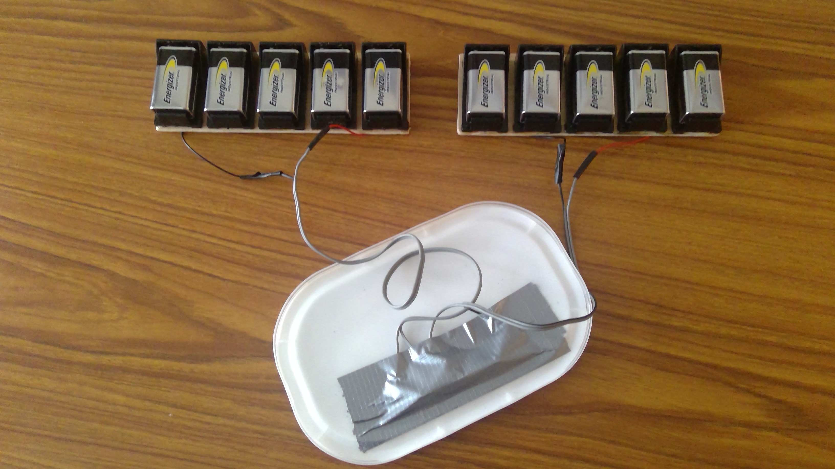
The PP3 batteries are not very large and you could argue for AA batteries instead. AA's would last longer but I would need 60 to make 90v. Some time ago I made a 90v battery pack using AA batteries - it worked well but because there were so many batteries, you only needed one dodgy battery or loose or corroded contact, and the battery box would then create a lot of noise that was difficult to trouble shoot. PP3's are approx. 500 mA/hr so if we limit HT consumption to 10 mA they should last for 50 hours which I think is OK.
Anyway, after putting the battery holders inside the battery box, here's a meter measuring 90v:
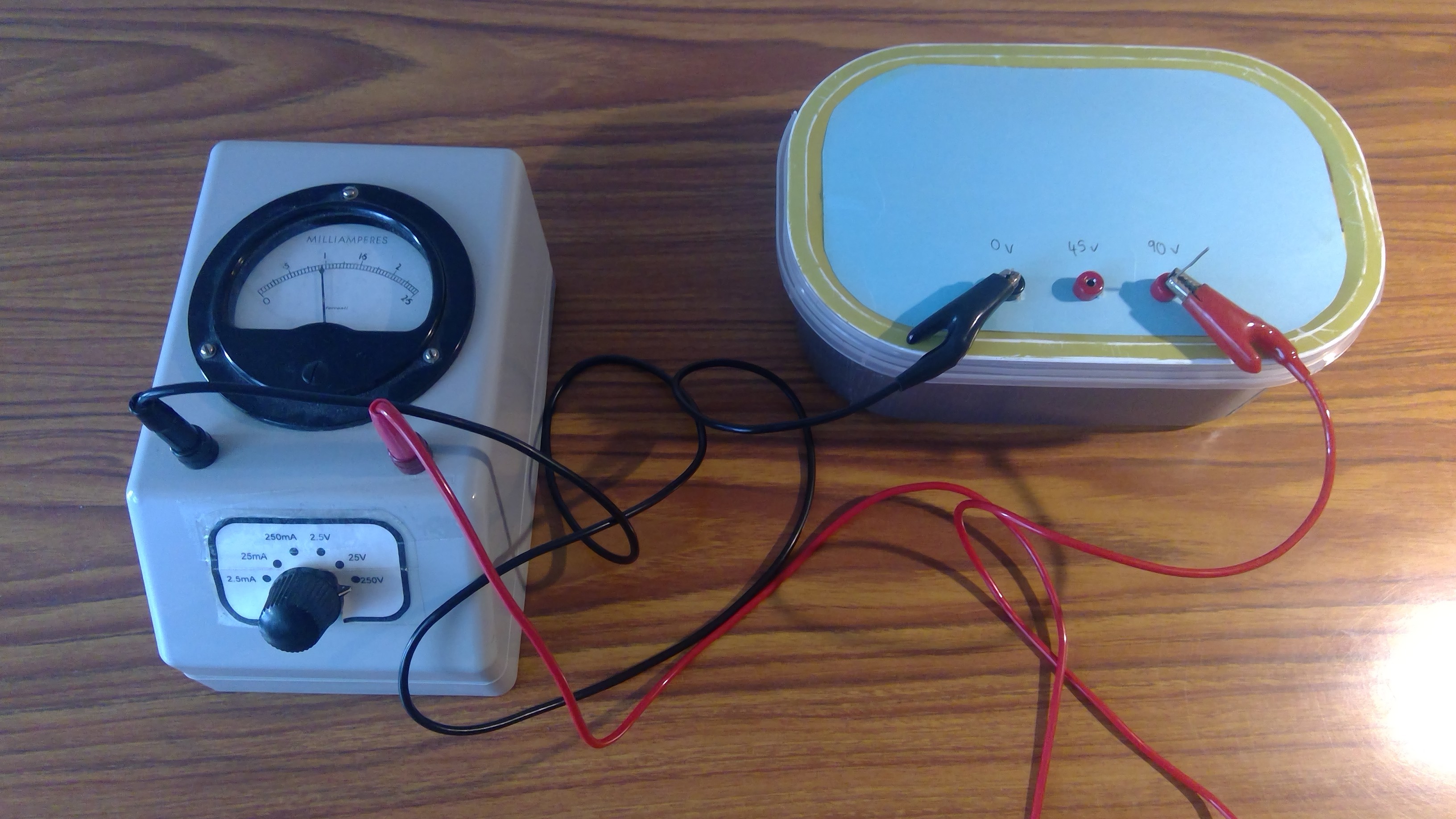
The battery box measures 18cm x 10cm deep x 6cm high, and any resemblance to an ice cream carton is purely coincidental! Ideally I would get a proper box that looks more like an old-style HT battery and has room for three of the 45v assemblies, but I couldn't find one.
Here are all the power supply elements together:
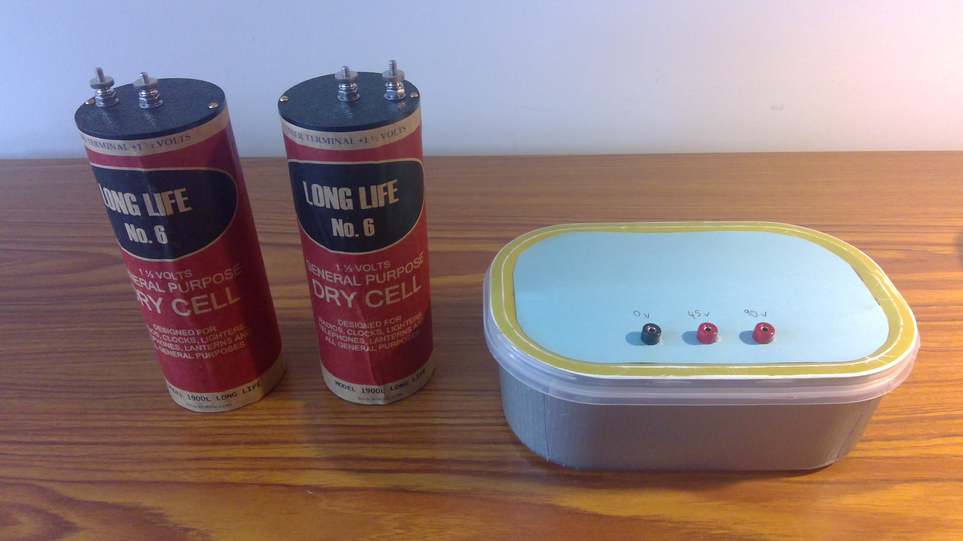
When I look at the size of these I realize transistors maybe aren't so bad after all :)
These power supplies don't have to follow what I did. As long as you have a LT supply for the filaments and an HT supply for the rest of the circuits, it will be fine. LT should match the valves you have, and HT should be 90v to 135v for loudspeaker reception, or can be 12v to 45v for high-impedance headphones. People that build reproductions of early-style valve radios sometimes fasten battery holders to the breadboard, and they clip 9v batteries to one another to make the HT.
Discussions
Become a Hackaday.io Member
Create an account to leave a comment. Already have an account? Log In.