 ElectronicABC
Supplies
GERBER PCB:
https://mega.nz/file/OUpVHYZD#Mfpq2xWVLr1cjbPYHXV5mMTLXBzj-y1jto0WRxB4DZA
SCHEMATIC DIAGRAM:
https://mega.nz/file/PIRXmSiT#WabeFgcGm-HkBtonvlKxTc7lTMXG2qUWpTLY12aOPaM
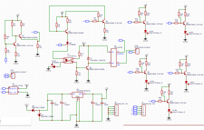
SCHEMATIC DIAGRAM
Here we will see the schematic diagram made in the easyeda software with all the electronic components and their respective values.
FUNCTIONING
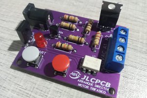
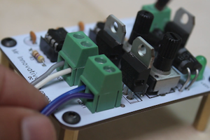
Here we will explain everything regarding our PCB, firstly we will feed our PCB with a voltage of 220VAC 60HZ since it has an integrated switching power supply TDPOWER 12VDC up to 1A that will allow me to control all electronic devices.
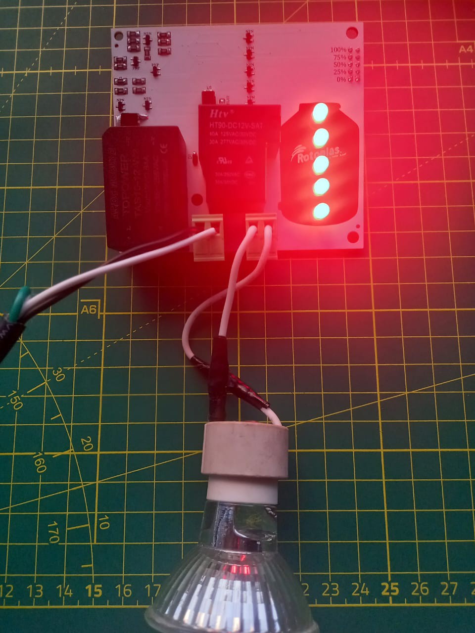
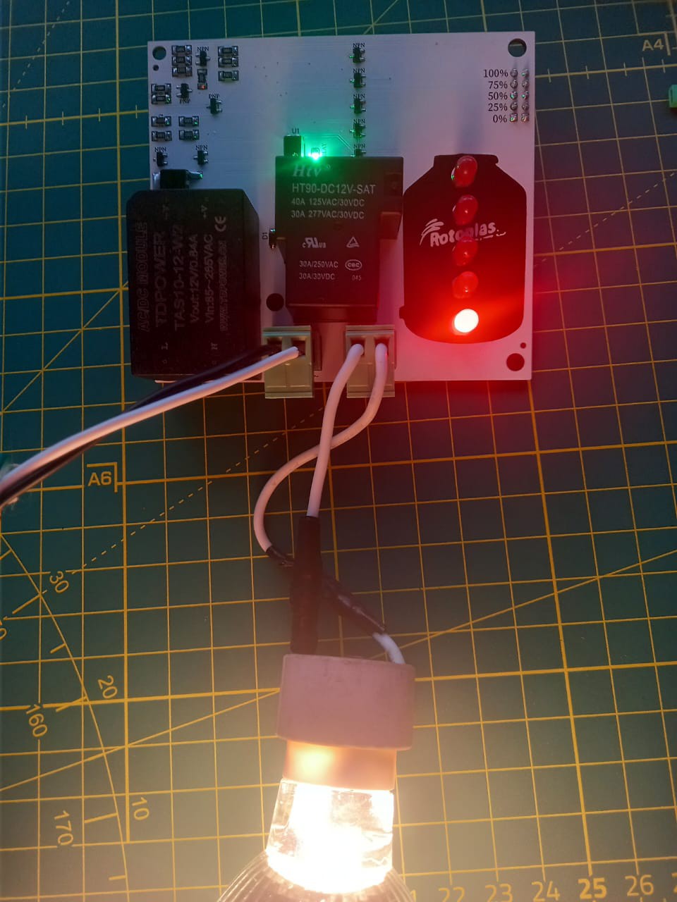
Then we perform the simulation with the pins from 0% to 100% with jumpers as a test or also with floating level sensors. The operation is easy when the tank level is below 26%, it will activate my motor so that I can pump and fill. The water tank, in turn, we can add a solenoid valve to open and close the pumping circuit in parallel to the second pumping motor, when it reaches 100% of the tank level, it deactivates the motor because it tells me that it is full and so it does not overflow. not very easy but we have indicator leds from 0% to 100>#/p###
This will allow me to see how level the water tank is.
when the output is activated at 220VAC 60HZ we can control a motor that supports up to 40A this will allow me to do it directly to the PCB since it can support its tracks up to 10A but if we need more than 10A we can reinforce the track with tin and have more current at the output.
This entire project is developed based on BJT transistors and resistors and for the SCR interlock, well, we will see below some devices and their operation in order to understand more deeply how they are behaving in this project.
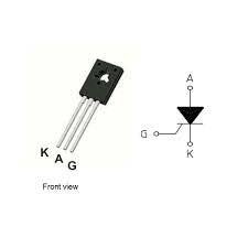
SCR C106MS SMD
C106MS SCR Thyristor
The SCR C106DG thyristor is an electronic device whose objective is to conduct electric current in only one direction, just as the diode does; but the SCR has to be on for this to happen.
When the thyristor is not conducting it is considered as an open switch. The C106MS has 3 connections: anode, cathode and gate (gate). Gate or door is responsible for controlling the flow of current between the anode and the cathode. It is a PNPN device designed for high consumption applications; for example light control, speed, temperature, warning systems, etc.
Type: SCR
Maximum Repetitive Peak Reverse Voltage: 400V
RMS turn-on current: 4 A
Non-repetitive transient current: 20 A
Peak gate power: 500 mW
Minimum operating temperature: -40 °C
Maximum operating temperature: 110 °C
Encapsulation: TO-225
Number of pins: 3
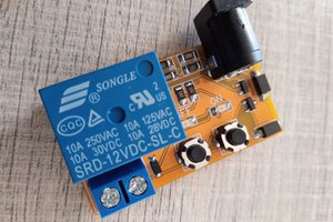
RELAY 40A 220VAC
Basically we could define the relay as an electrical switch that allows the passage of electrical current when it is closed and interrupts it when it is open, but that is electrically activated, not manually.
The relay is composed of a coil connected to a current. When the coil is energized, it produces an electromagnetic field that causes the normally open relay contact to close, allowing current to flow through a circuit to, for example, light a lamp or start a motor. When we stop supplying current to the coil, the electromagnetic field disappears and the relay contact opens again, leaving the electrical circuit that went to that lamp or motor without current.
What are the relays for?
The relays are used to activate a circuit that has a considerable consumption of electricity through a small power circuit -12 or 24 volts- that magnetizes the coil. Suppose we want to motorize a garage or farm entrance door. For this we will need a remote control that manages to activate through a receiver that small power charge that starts the operation of the relay: the coil will magnetize and close the electrical circuit that feeds the motor that is used to open the door. We can also use it to turn on machines and motors, lighting systems, etc.
Sometimes, we find ourselves with lighting circuits that need great power for their operation. By...
Read more »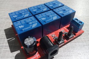
 Mrinnovative