 Vijay
Vijay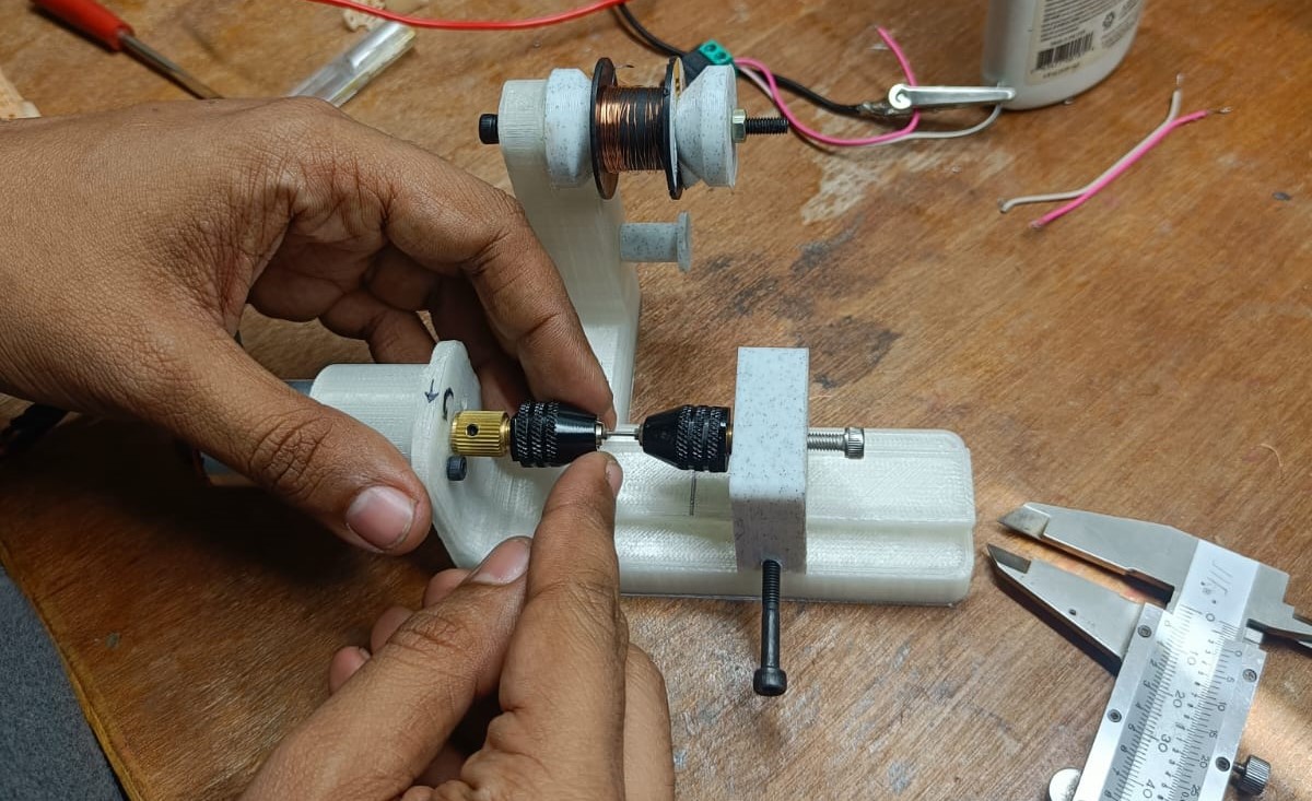
I figured that the trickiest parts of the build would be the winding of the ultra-small coils, so I designed a coil winding tool to help with this process and make it easier
In the future, this step could be completely automated, similar to commercial coil-winding machines.
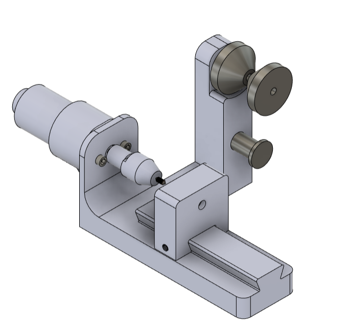
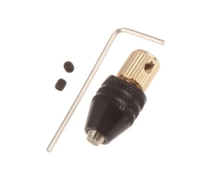
I used a couple of drill chucks (https://robu.in/product/3-17mm-mini-electronic-drill-chuck-range-0-5-3-2mm/) and a 4mm shaft gearbox DC motor with an encoder(https://robu.in/product/n20-6v-125rpm-metal-gear-motor-with-encoder-d-type-shaft/) for the winding jig. Ive included the assembly file in the file download section and that should be enough for you to figure out how to assemble it.
Details of the winding process itself will be provided in the instructions section. The winding tool looks very similar to a miniature lathe, with a headstock being one drill chuck connected to the motor, and another drill chuck connected to the headstock. The headstock can move along the length of the took on a dovetail groove that can be locked at a set position to determine the length of the coil to be wound.
There is a tensioning mechanism to center the wire spool and make sure it is taught against the winding.
All components were 3D printed on an FDM machine.
I used two 2.5mm diameter - 1mm thickness spacers which were cut on a wire EDM machine to act like flat faces to constrain the coil winding, as well as to give an indication that the maximum allowed diameter of the coil is achieved. The two chucks are tightened on two ends of these spacers to constrain the length of the coil winding.
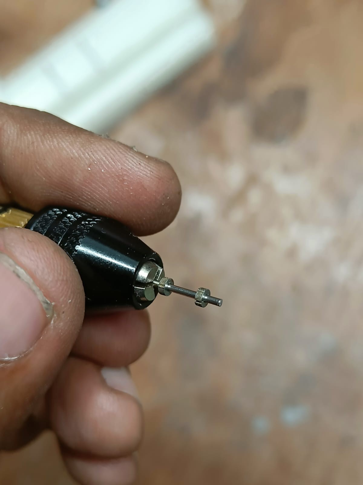
You can see in the video below that despite the jankiness, it still works very nicely and produces perfectly wound coils. I used the slot on the EDM cut spacers (That is needed anyway for the wire to cut out the inner hole) to hold one end of the wire when it starts winding.
The final assembly for the tool can be downloaded here. Export the relevant parts as an STL and print it on an FDM 3D Printer. The design can definitely use some improvements so I've included the source files to make modifications and improvements to the design.
Discussions
Become a Hackaday.io Member
Create an account to leave a comment. Already have an account? Log In.
Hey can I please know what was the gauge of the wire being used here ? Also how much volts did it run on ? Specs of the solenoid coil would be highly appreciated as I am working on a similar system.
Are you sure? yes | no
That's an unexpectedly perfectly wound coil considering it doesn't use any kind of automated guide.
Are you sure? yes | no
I was surprised too at first, initial attempts were mediocre at best. Out of luck, found that if the wire feed happens from the middle of the shaft, the coil winds perfectly. I suppose for such a small coil (6mm in length) you can get away with not having an automated guide, but may still be needed if one wants to wind the coil faster.
Are you sure? yes | no