Demonstration
Overview
The Helping H.A.N.D.S. project is based on the existing open-source Robot Nano Hand project. Using the existing Robot Nano Hand provided us with the mechanical design and assembly instructions, leaving us to assemble the hand and focus on hardware and software development.
The system block diagram below shows how all the major project components interact.

The ESP32 interfaces with the microphone and controls the movement of the hand, while the more computationally expensive speech recognition takes place on a connected laptop.
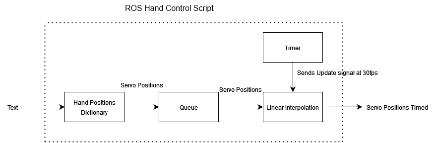
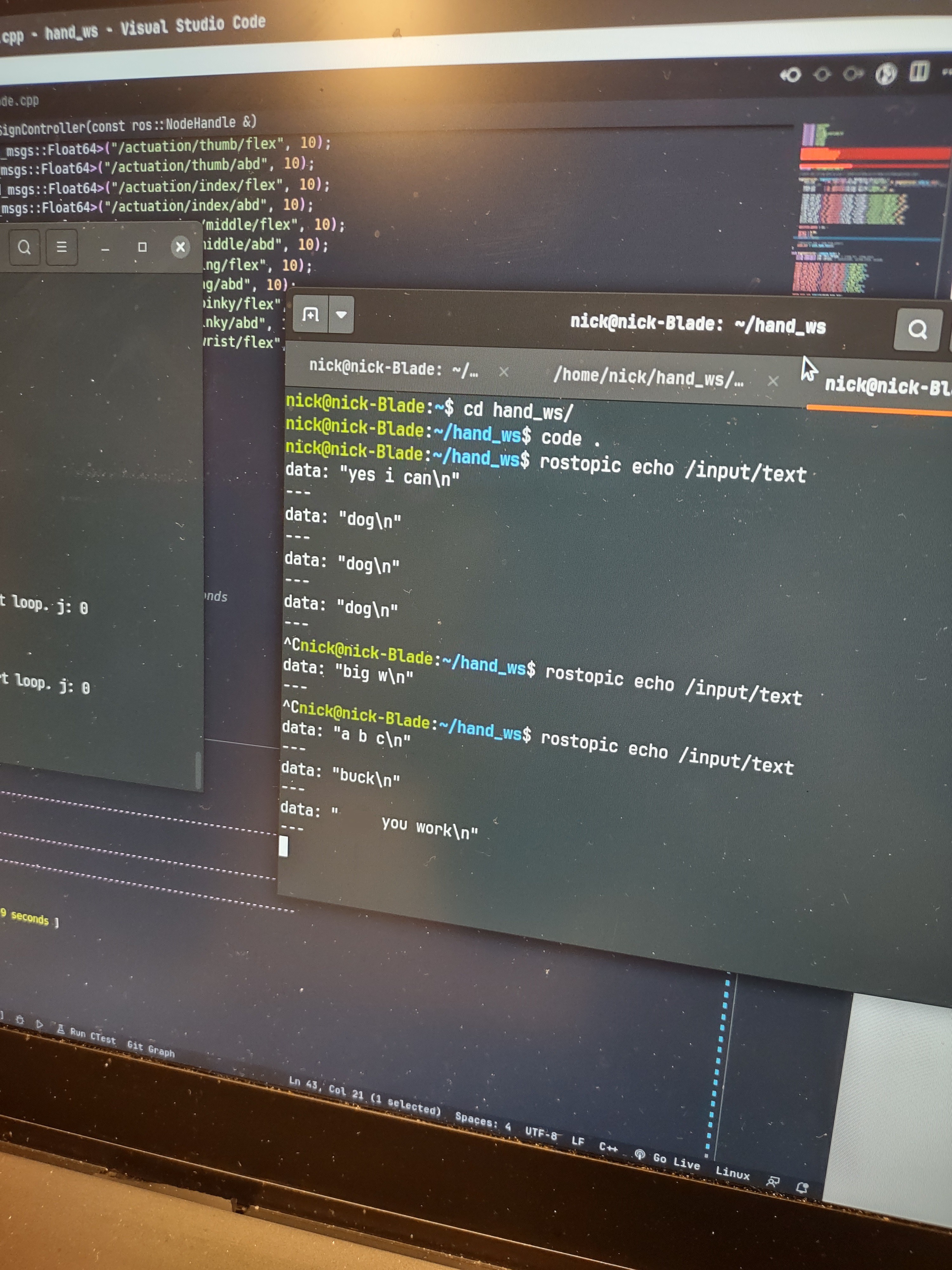
The hand is controlled by a script running on ROS on the ESP32. Characters are fed into the script one at a time from the .txt file generated by the speech detection script. Each character is associated with a pre-calibrated position for each servo motor. These positions are read from the dictionary of hand positions and fed into a queue. Periodically the position of each servo is updated to move closer to the end position.
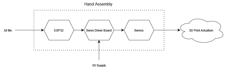
To generate a PWM signal for each servo, the 16-channel PCA9685 servo driver is used. The servo driver is supplied with power from an external power supply, capable of delivering up to 3 Amperes of current. Finally, changing the position of the servos alters the position of each digit on the hand.
Microphone
An Adafruit I2S microphone breakout board is used to collect user input. Audio is detected by the microphone and sent to the ESP32, where the signal is then forwarded to the connected laptop.
The microphone receives power directly from the ESP32. Currently, the system can record and process three seconds of audio at a time. Audio recording is started by pressing a button on the ESP32.
Speech Recognition
After the audio signal is received by the laptop, it is converted into a .wav file and sent to the speech recognition script. Our speech recognition software is implemented with the open-source Vosk speech recognition library. The Vosk library is compatible with over 20 languages and dialects and has a lightweight, offline version, which means the system does not require access to the internet to operate.
Word Processing and Hand Control
The word processing and hand control software interfaces with the audio detection software and the robotic hand. After audio detection is complete, a .txt file is passed back to the ESP32. On the ESP32, the .txt file is broken down into individual letters, which are mapped to servo motor positions. Each letter, represented as a set of motor positions, is fed into a queue, which is periodically polled by the motor control script. The motor control script saves the new position and the previous position. Next, the motor control script gradually increments the position from the previous position to the current position to ensure smooth operation. Once the desired position has been reached, the motor control script pulls the next hand position corresponding to the next letter from the queue.
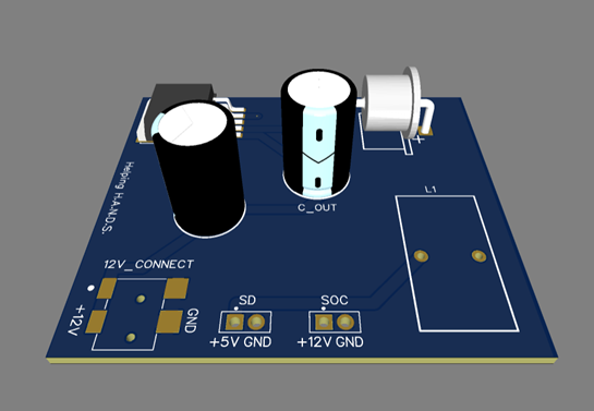
Power Management Circuit Board
The power management circuit board is the main power supply for the ESP32 and the servo motors. Using a central printed circuit board (PCB) to power the system ensures the device will be portable and eliminates the need for drawing power from a laptop or a lab bench power supply. The board receives a regulated 12 Volt DC input from...
Read more »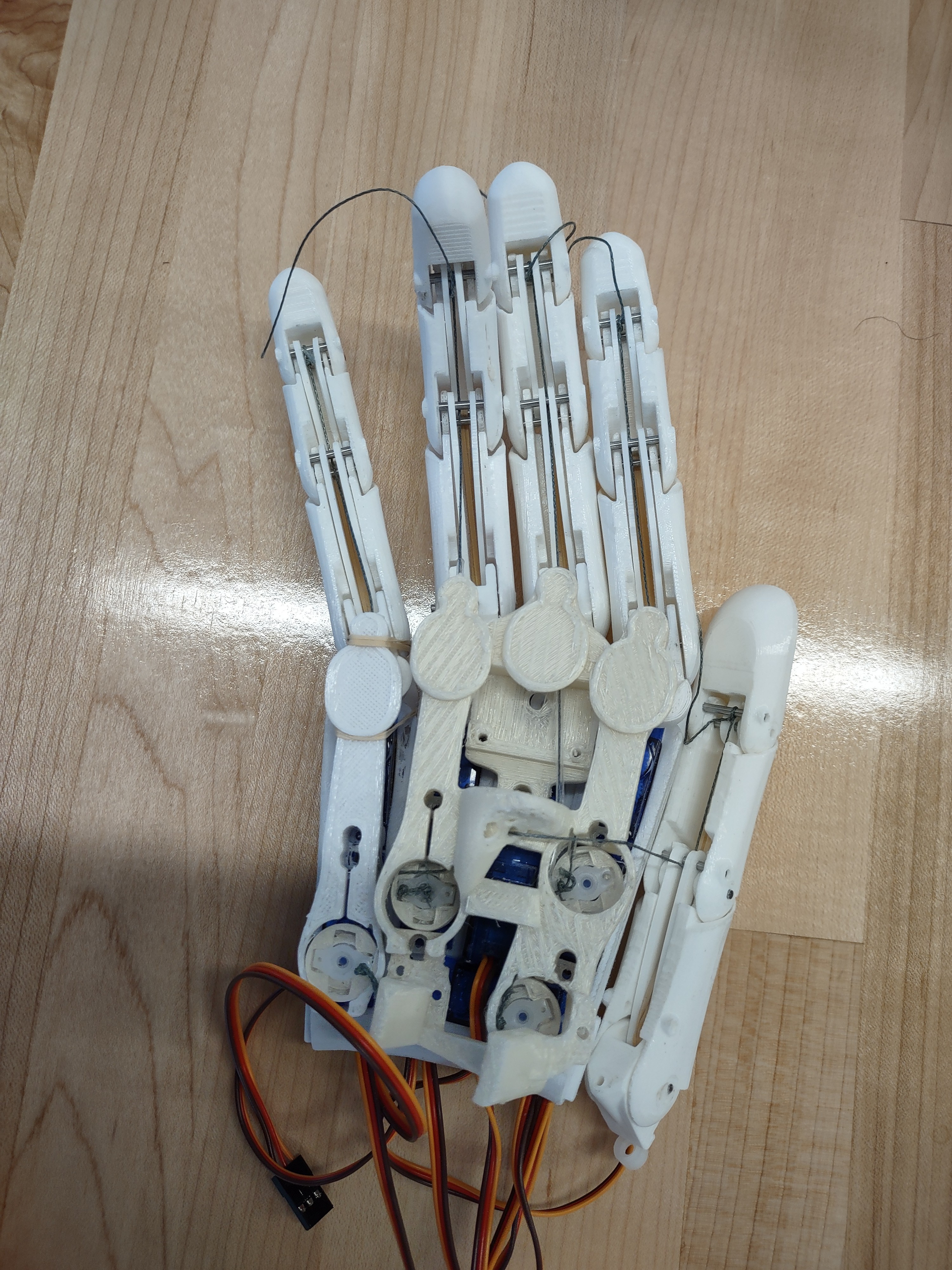
 Tyler Ward (Scorpia)
 Jean-François Duval
 Alex Muir
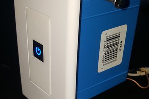
 Joe Menard
Looking forward to seeing more of this project :)