 Andy Nicol
The Basics of MRI and NMR Spectroscopy
Detecting the fundamental signal underlying Magnetic Resonance Imaging (MRI) is surprisingly simple. In MRI, the Larmor frequency is crucial for understanding how the magnetic moments of nuclear spins align with or against an externally applied magnetic field, and how they subsequently precess around the direction of the magnetic field. This precession forms the basis for generating the signals used to create MRI images. Similarly, the Larmor frequency is essential to understanding Nuclear Magnetic Resonance (NMR) spectroscopy, a powerful analytical technique that exploits the magnetic properties of atomic nuclei to study the structure, dynamics, and interactions of molecules. In NMR, the Larmor frequency determines the rate at which nuclei precess around the magnetic field direction, and this precession is used to generate the signals that form the basis of the NMR spectrum.
Who was Larmor and how did he discover this frequency
https://mriquestions.com/who-was-larmor.html
Earth's Field NMR
Just as in MRI machines and NMR spectrometers, which typically employ superconducting or powerful rare-earth magnets, some atoms within liquids also naturally precess in the Earth's magnetic field. The Larmor frequency is dependent on the strength of the applied field, so hydrogen atoms in the Earth's field exhibit a very low precession frequency. Conveniently, this frequency falls within the range suitable for a standard audio amplifier.
Earth's Field NMR entry at Wikipedia
A demonstration of 1D Magnetic Resonance Imaging in Earth's magnetic field. Although production of the Magritek TerraNova ceased by 2023, it remains the gold standard for commercial EFNMR/EFMRI systems.
A Simplified Approach to NMR Signal Detection
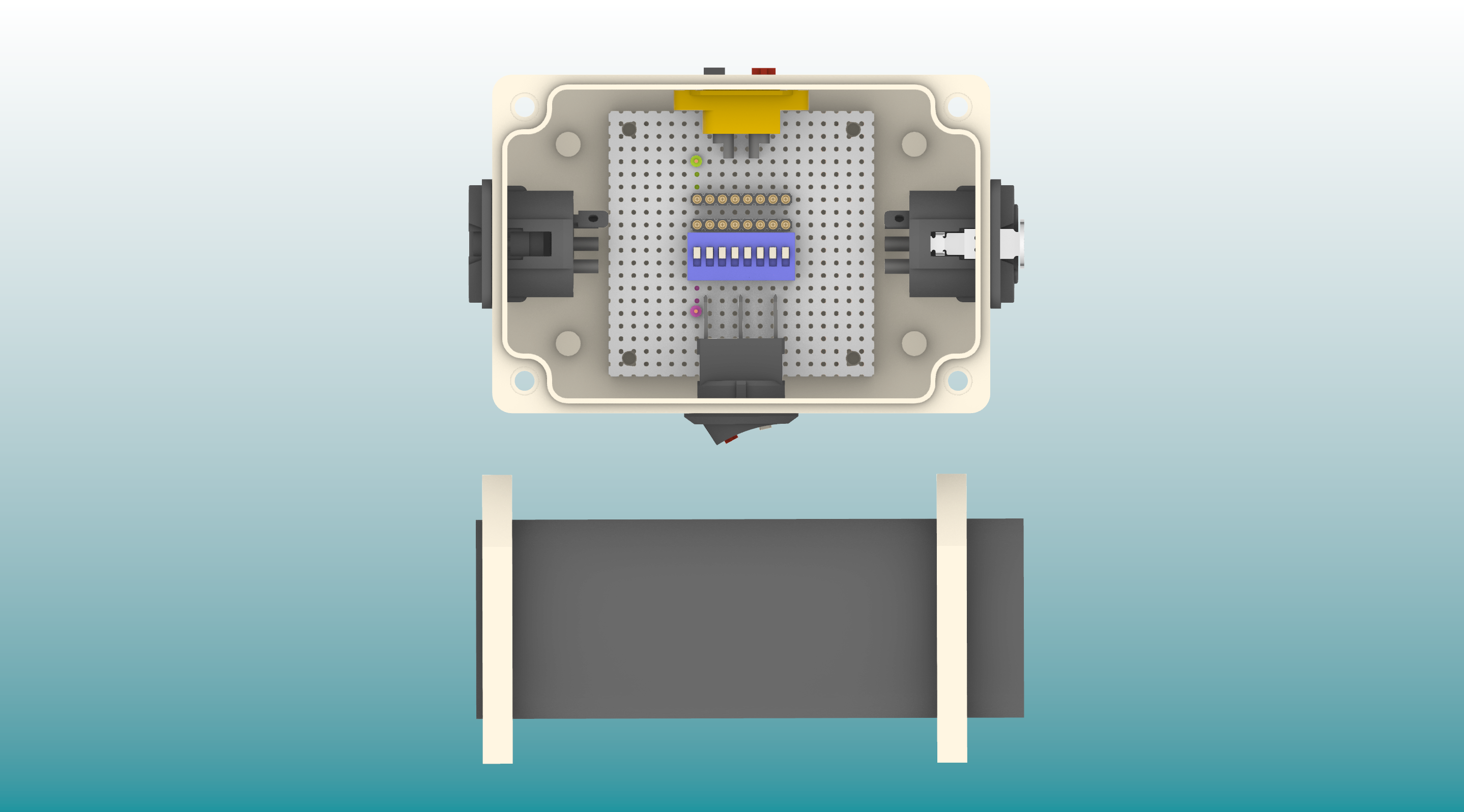
This guide aims to demonstrate how to use a widely available mid-range USB audio interface to bypass the immense complexities typically encountered when designing a reliable, portable, ultra-low noise amplifier and ADC suitable for detecting signals from hydrogen atoms within the Earth's magnetic field. By using only a manually operated three-way switch, we will also bypass the complexities of NMR pulse programming and eliminate the need for digital control circuitry. The system provides a minimal overhead approach to Free Induction Decay (T2) signal detection.
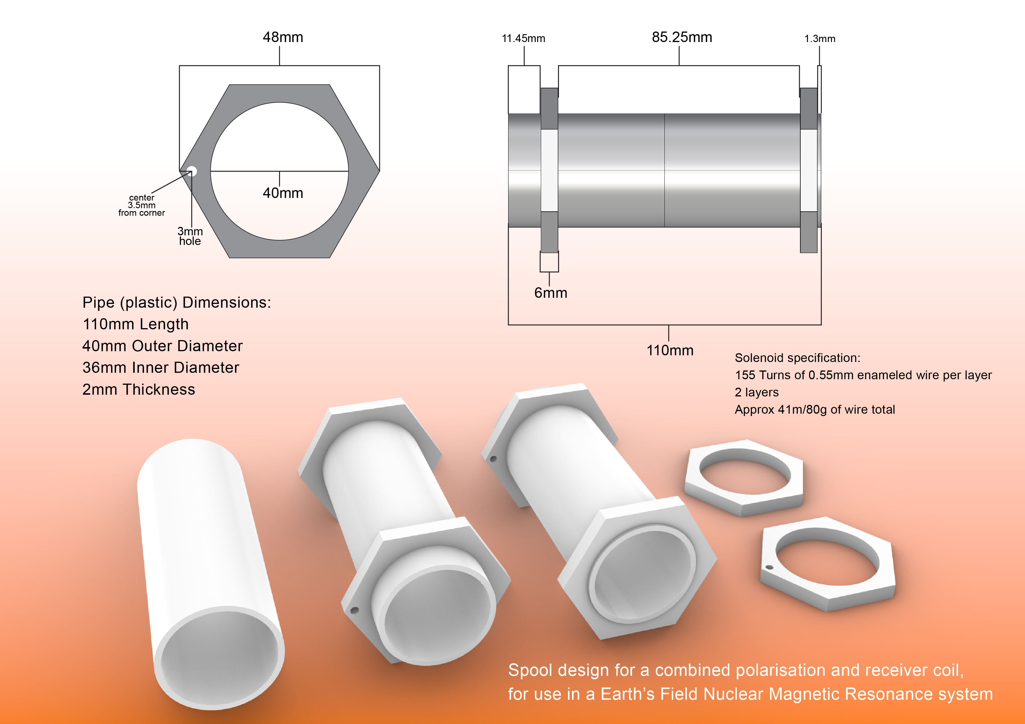
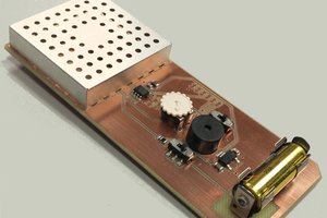
Polarization and Detection Coil Design
In addition to the design of the amplifier and ADC, the polarization and detection coil design is often another confounding technicality in Earth's Field NMR (EFNMR) system design. Many designs require two or more coils and necessitate fine wire with thousands of turns. This design, however, employs a short two-layer coil composed of relatively easy-to-wind 0.55mm wire, making the project more accessible for most people.
Signal Visualization and Software Tools
An overlooked component of the EFNMR signal detection process is the visualization of the received signals. By using a popular off-the-shelf audio interface with robust multi-platform drivers, we can connect directly to a phone, tablet or laptop and download free spectral analysis tools with high performance waterfall (STFT) outputs. These types of tools are ideal for detecting live, one-shot EFNMR signals, even indoors in medium-noise urban environments, with no additional hardware filtering or shielding needed. Most programming languages have libraries for USB audio devices, making the project suitable for custom software development.
Portability
Because EFNMR involves measuring the extremely subtle magnetic movements of atoms; magnetic interference is critical to success. The difference between successful signal detection or not can come down to a vertical or horizontal movement of only 30cm. It is crucial to be able to freely rotate the coil in order to navigate the local magnetic field. A general use EFNMR detection coil must be highly adjustable and mobile to ensure the...
Read more »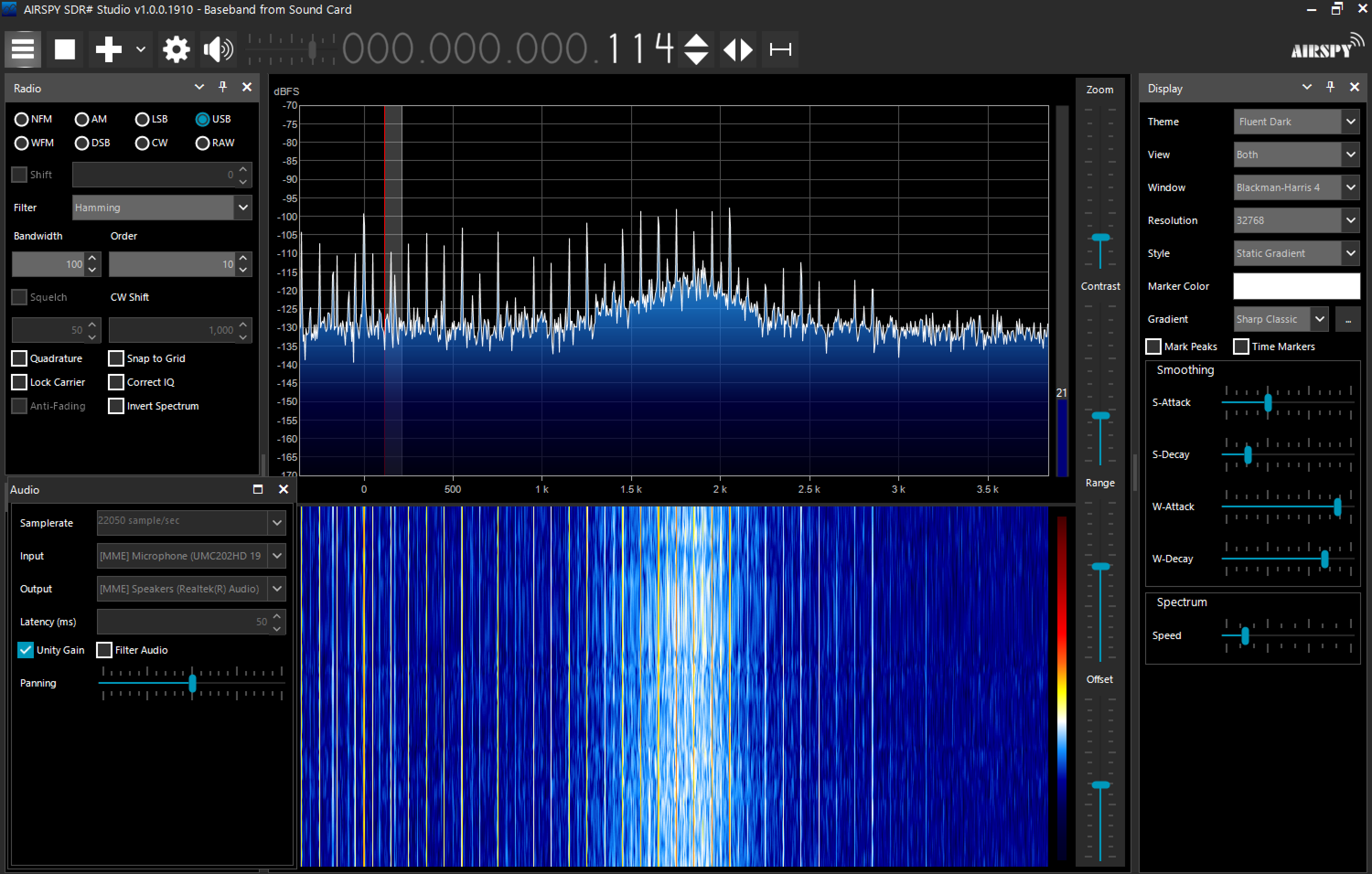

 Carlos Garcia Saura
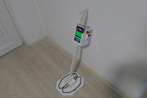
 mircemk
 Ever
Ever
 Brett Walker
Hi Andy,
Nice project! Not sure if you are aware, but there is a company that makes an EFNMR spficially for teaching undergrad physics majors about the phenomenon. They specifically make instruments to be used in advanced undergraduate physics labs and have a couple of different NMR-based apparatus, including an EFNMR. Also, at the bottom of this webpage there are listed some "add'l resources" which make for interesting reading! https://www.teachspin.com/earths-field-nmr