 Adam Oakley
I made a simple version of this device using an MSP430 Launchpad and a basic constant current load. Using the USB-Serial capabilities of the MSP430, I sent the battery voltages over time to my PC and logged them to a file. That data can then be used in a program like excel to graph out the battery discharge.
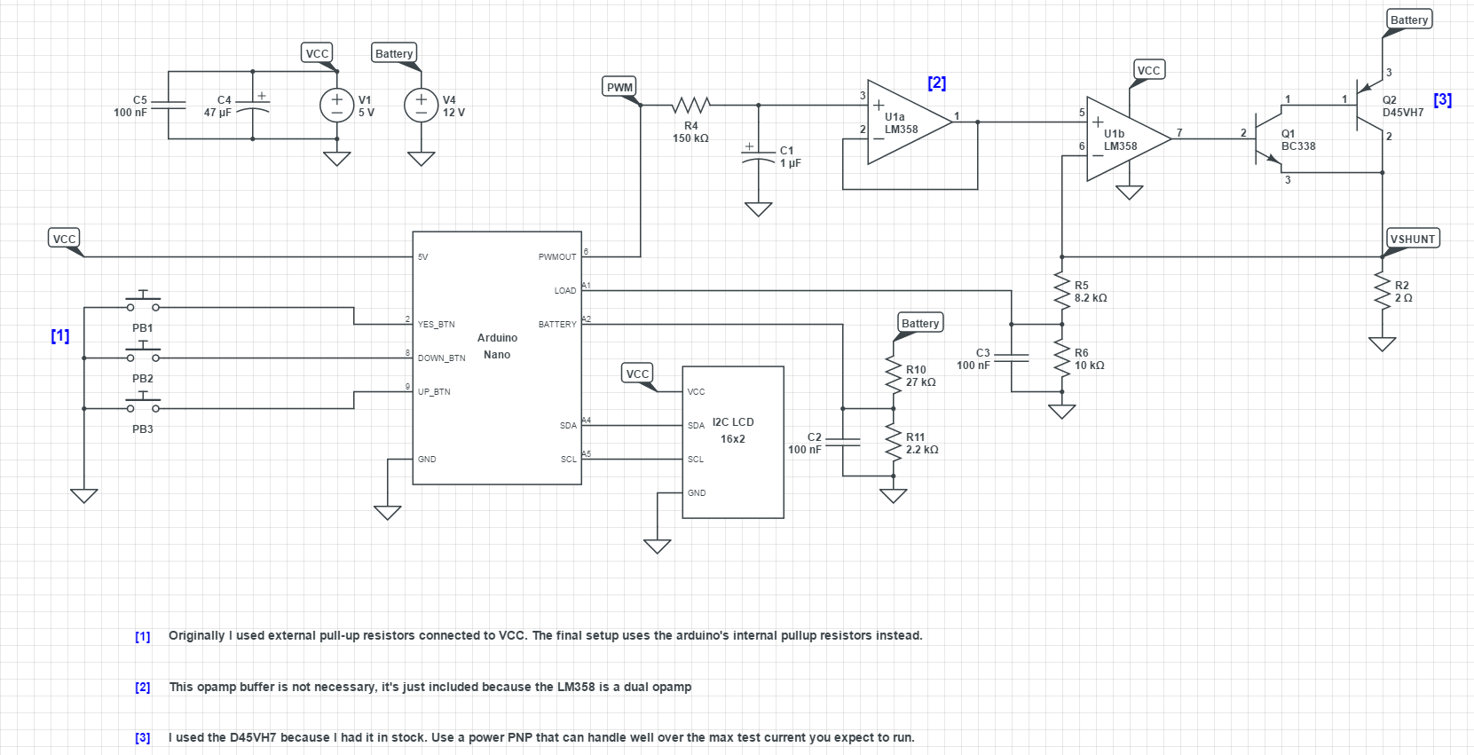
This project now uses an Arduino Nano, as seen in the schematic below:


 Saabman
 DrYerzinia
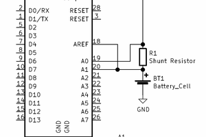
 Matthew James Bellafaire
It is shown in the second picture down of:
https://hackaday.io/post/11015
It is a vented cage to allow the heater wire to breathe. I had thought of using a fan to keep the temps down, but really have not had a problem yet. The coils do not glow red except one of the mid range resistance values. It is only a dull red.
I am looking forward to the posts and source if possible. . .