 Kuba Sunderland-Ober
Motivation
I wanted a basic 4.5 digit milliohm meter, for battery operation, designed to be affordable and use common, inexpensive parts, with some flexibility there: higher-cost part substitutes will perform better.
Op-amps and comparators figure prominently in the design and implement most of its functionality.
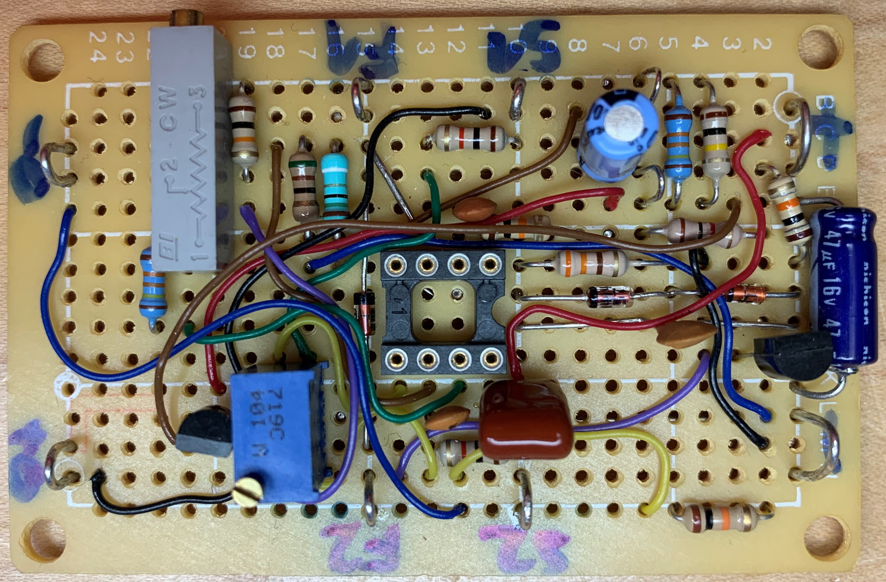
The design was prompted by and is a "reply" to Electrolab's milliohm meter project in the following video: Monte um Milliohmimetro super preciso!!! YouTube video. It demonstrates similar or better performance using jellybean general-purpose parts that were available in the late 1970s (save for the digital display), from a much lower supply voltage.
It is a stepping stone for a future project.
Requirements
- 3V to 5V operation,
- bare bones BOM cost around $15,
- reasonable accuracy with jellybean parts,
- 1Ω full-scale single range with some overrange capability,
- 4-wire operation only,
- zero- and scale factor (gain) adjustments,
- digital display with 1mΩ or better resolution,
- power supply monitor/indicator,
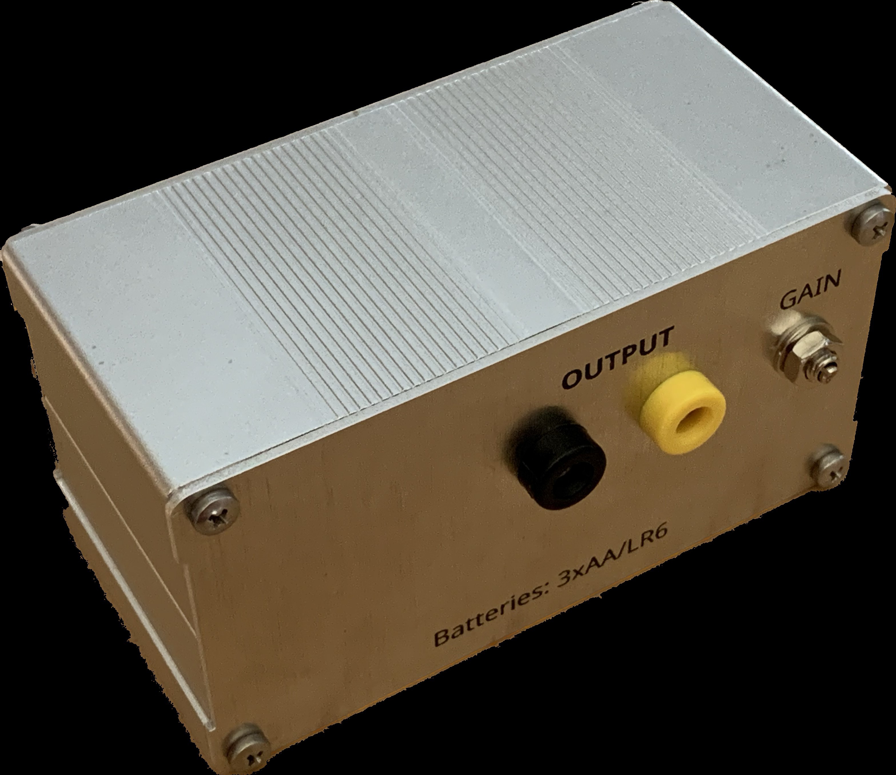
- 1V/Ohm analog output for e.g. data logging
- four op-amps (two duals), two comparators (one dual)
This is a Prototype!
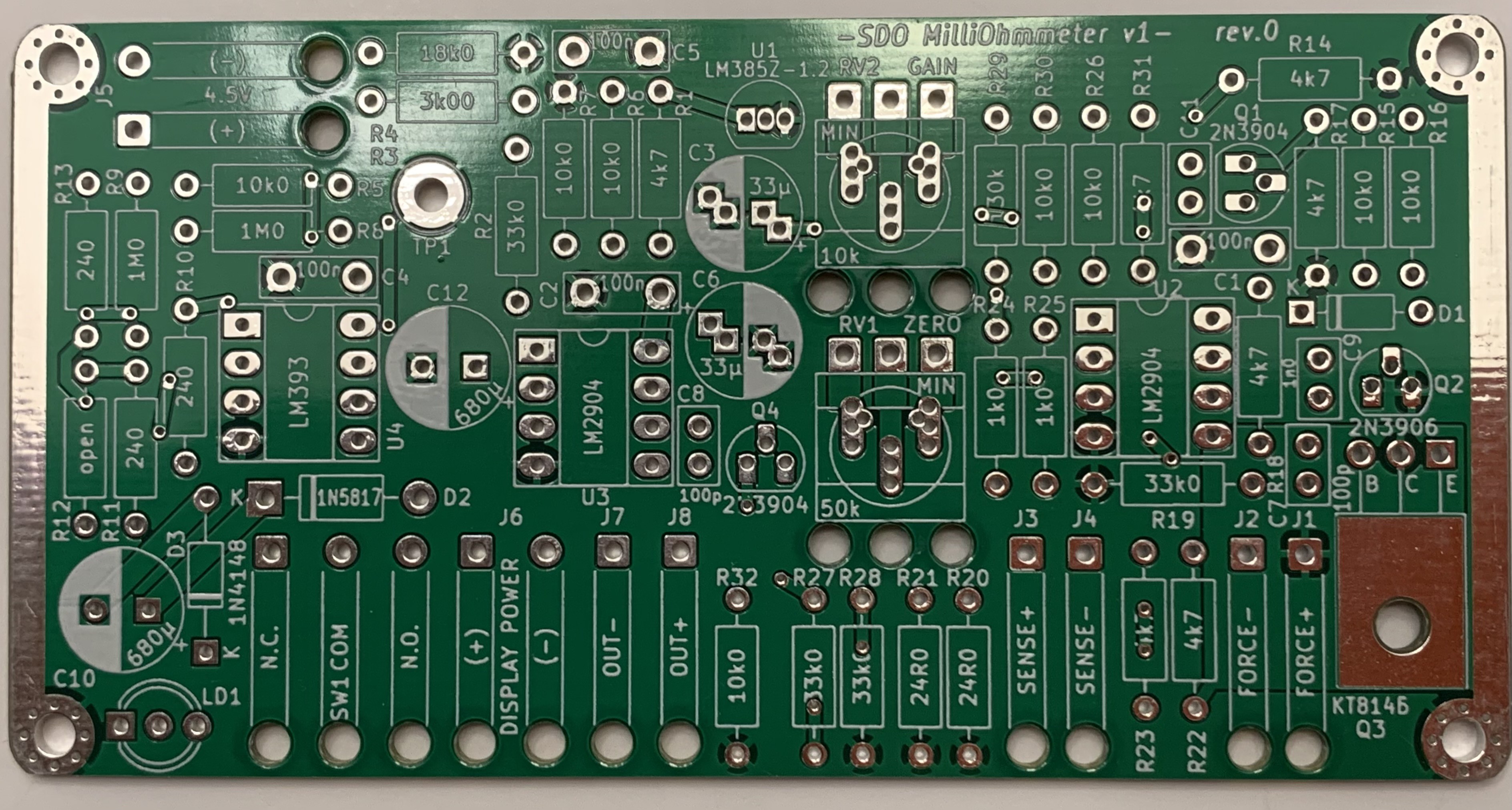
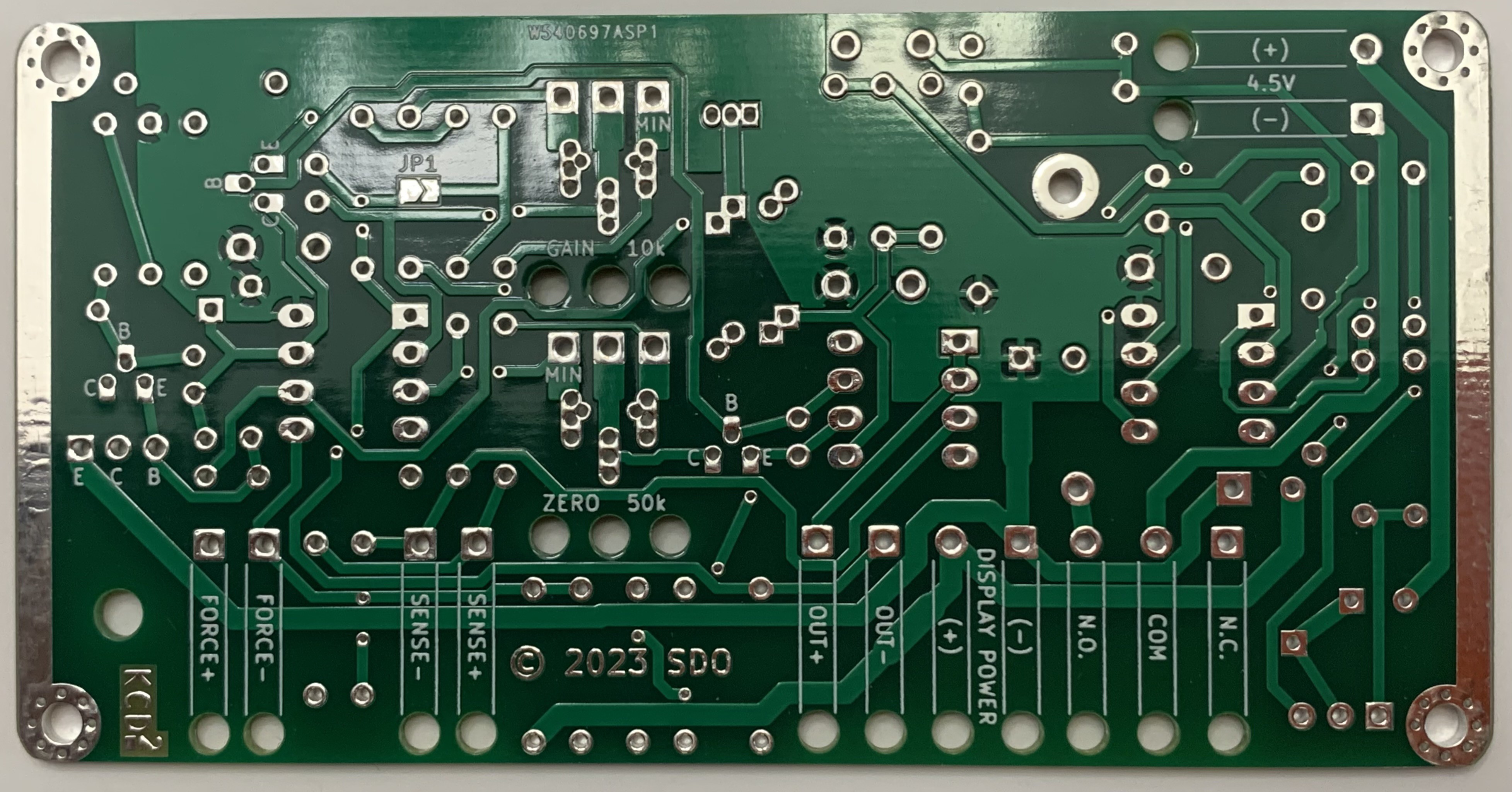
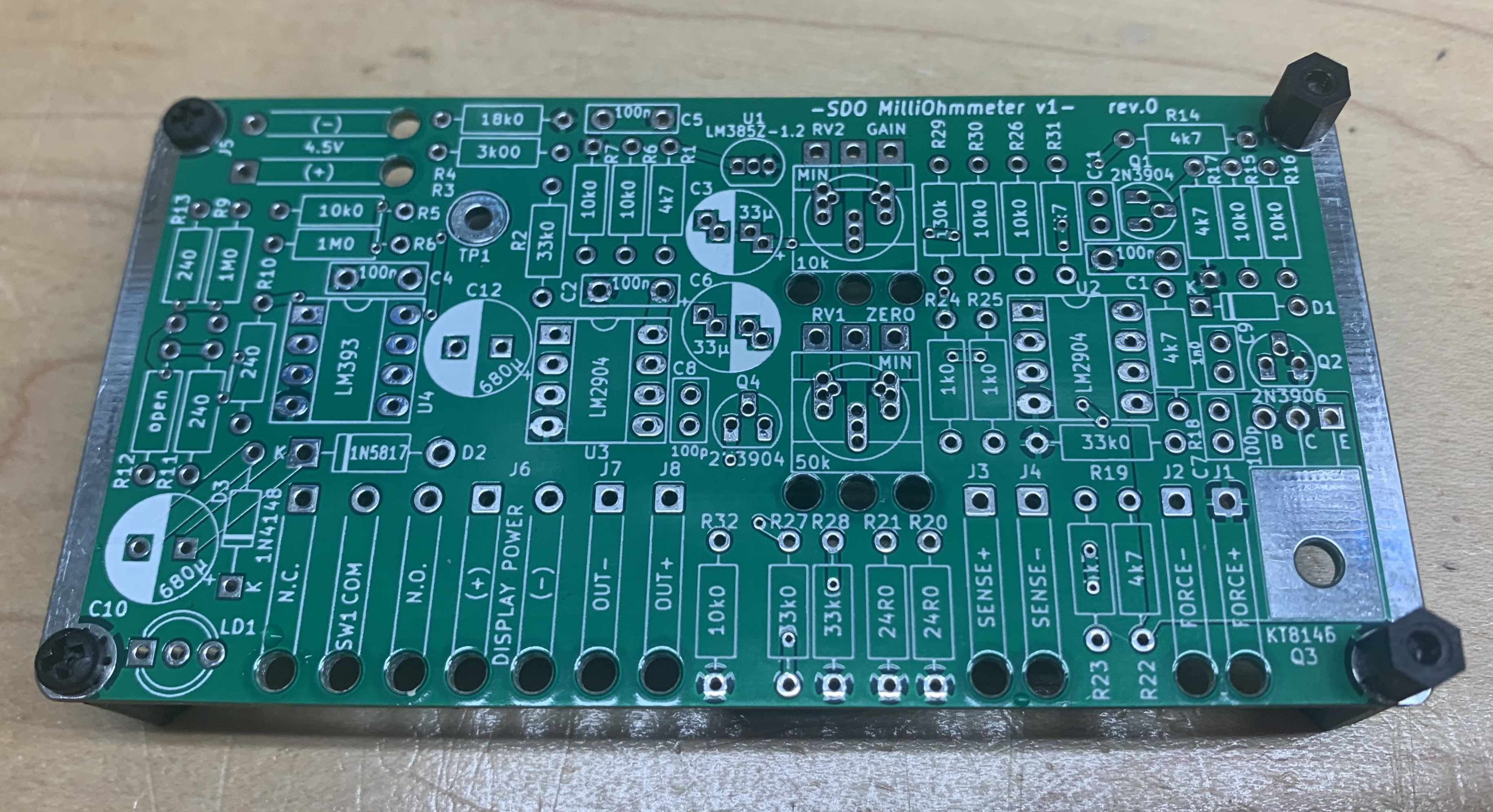
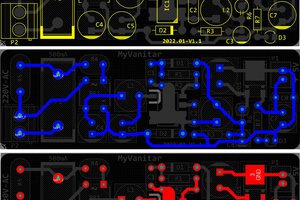
The design as shown suffers from problems not unknown to those who build a new design for the first time. My first mistake was to lay out the PCB based on the box dimensions from the eBay listing. Those dimensions turned out to be a bit of a "ballpark". The board dimensions should be 100x49mm to ensure fit.
The PCB is too wide by 1-2mm, and had to be sanded down to fit between the front and back plates of the enclosure.
The wire stress relief features are somewhat big for the wires used.
There's no provision for 2-wire measurement even though it would have been a reasonable requirement to have.
I've bought the PCBs from PCBWay, without any sponsorship. I am very happy with the quality so I can gladly recommend their "5 for $5" product. The size of the boards is limited to 100x100mm for that price. Larger boards cost more.
The laser-cut panels were ordered from Ponoko, without any sponsorship. Again, they provide high-quality product and I can recommend their service based on this experience.
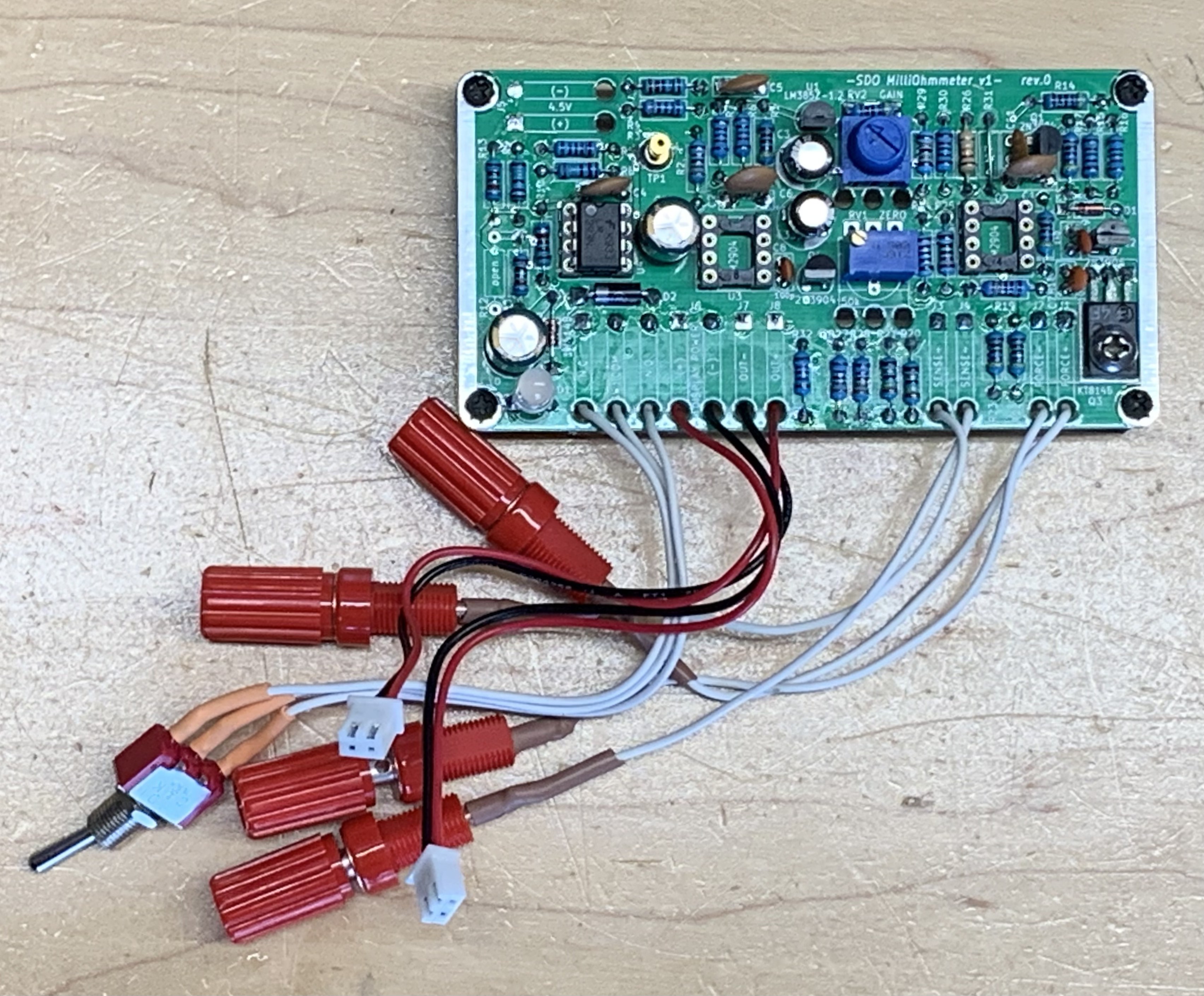
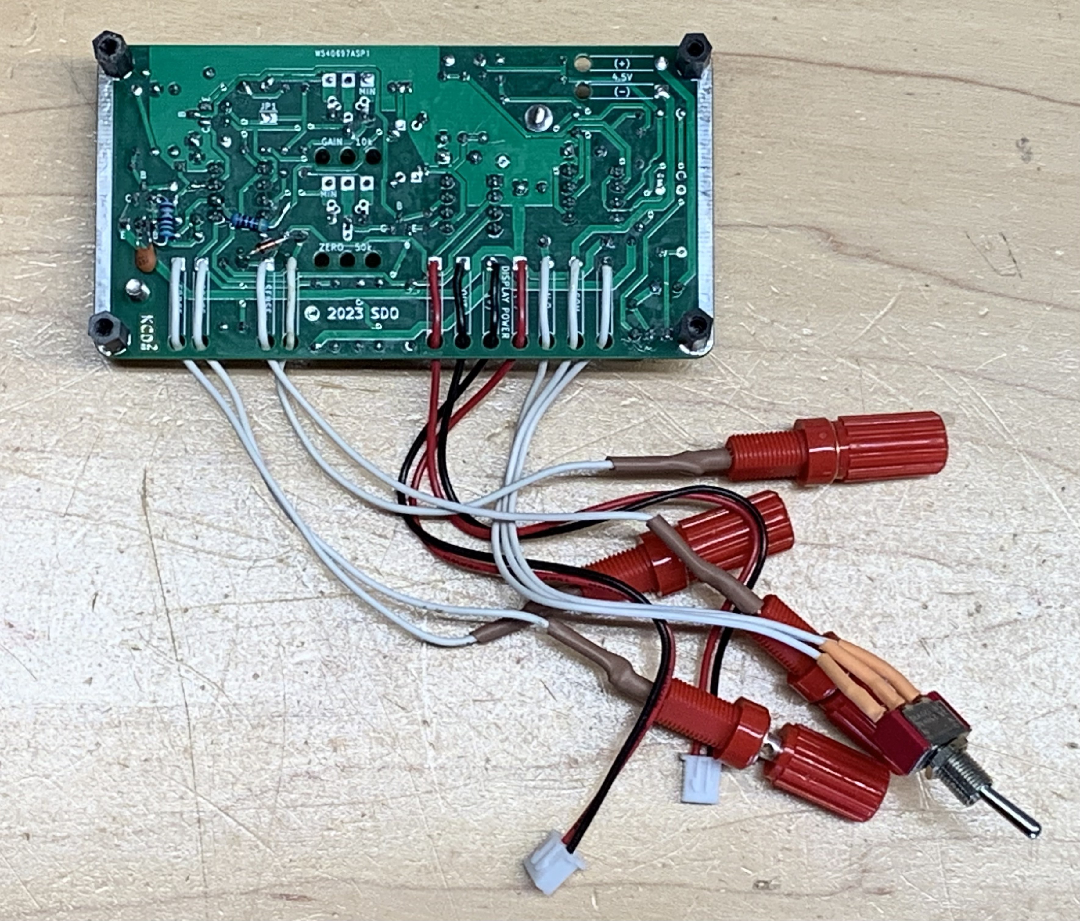
Enclosure and Controls
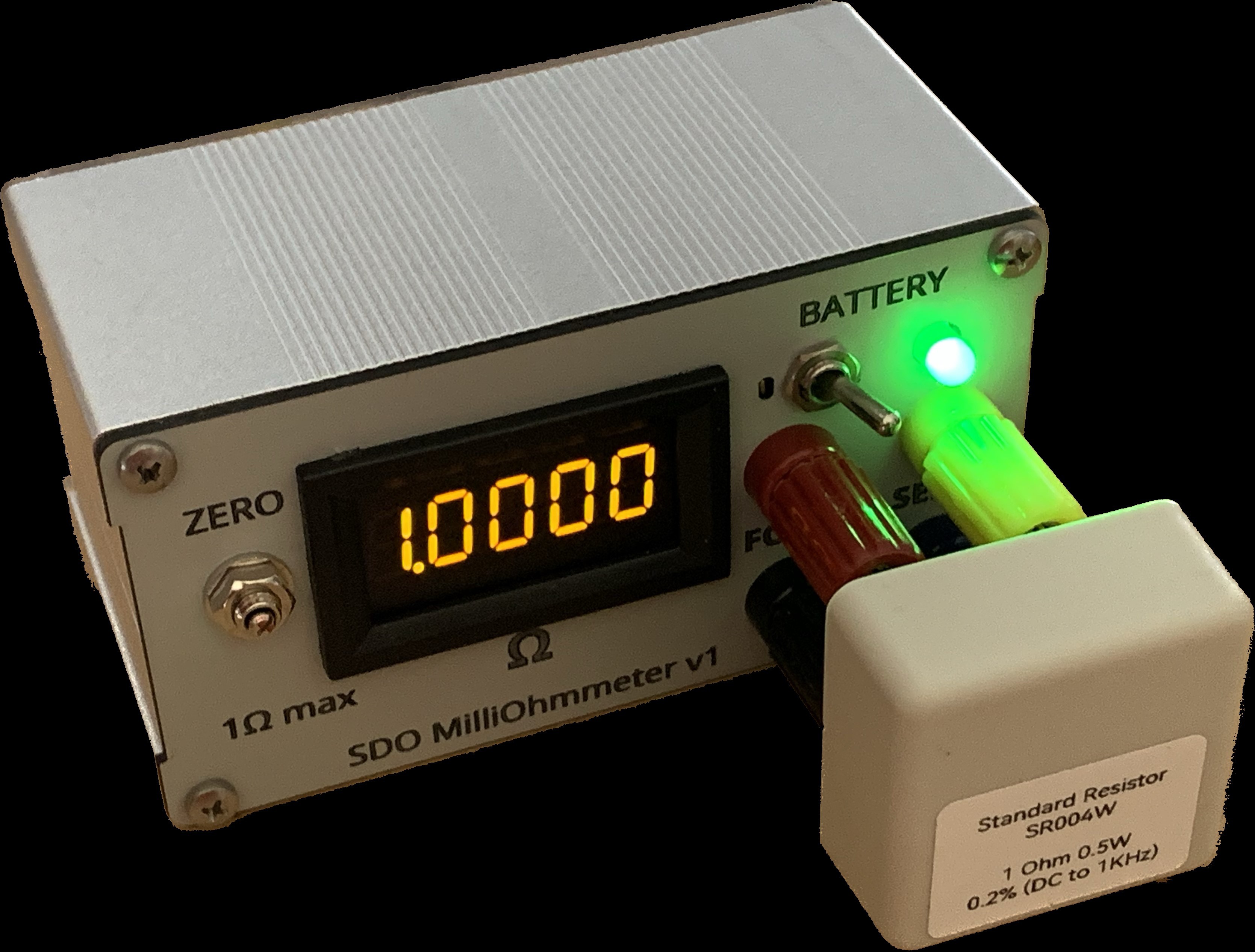
The meter is packaged in a two-part extruded aluminum enclosure. On the front, there are:
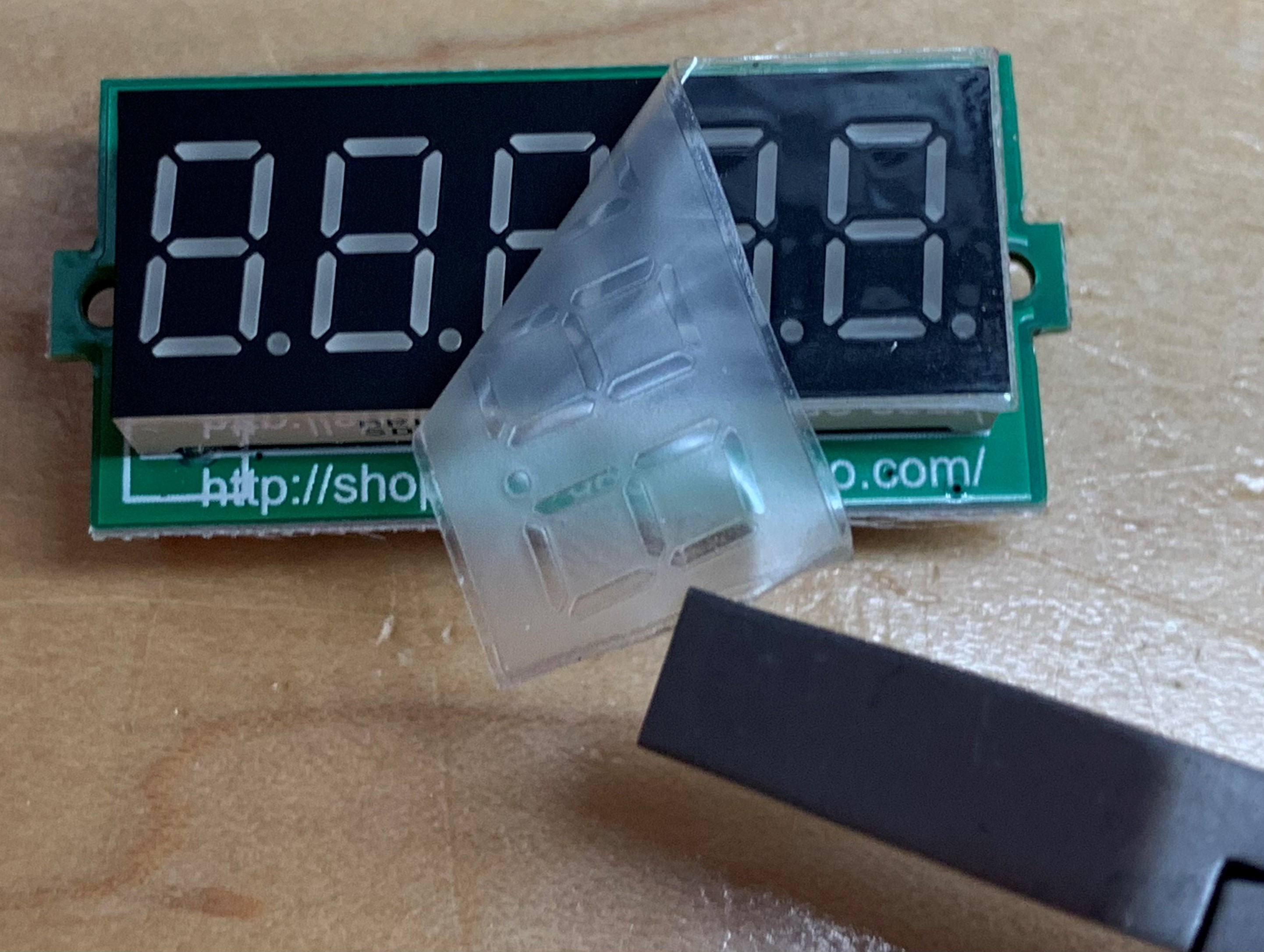
- a 4.5-digit resistance display,
- power switch,
- tri-color battery voltage indicator,
- force and sense binding posts (jacks),
- a zero adjustment trimmer.
 W4KRL
W4KRL
 hesam.moshiri
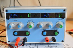
 w_k_fay