 ElectronicABC
GERBER PCB:
https://mega.nz/file/zZ5hmRSa#dQFUK1ZjS5RdYPjYKaGl5hNydDziKjKeKmunMRPJ75U
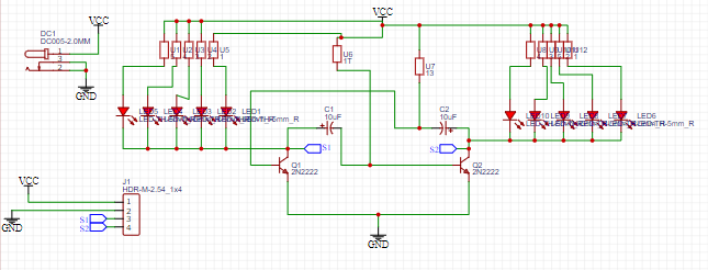
SCHEMATIC DIAGRAM
A very easy electronics project: it is an astable oscillator that causes the LEDs that appear in the diagram to blink.
Here we will see the schematic diagram made in the easyeda software with all the electronic components and their respective values.
FUNCTIONING
This circuit is a typical and simple configuration of an astable circuit with transistors. We will use some values of the components so that the frequency of this circuit is low and to be able to visualize the On-Off states, in two LEDs. If we used a very high frequency, we would see the LEDs always on due to the persistence of the retina even though it really wasn't like that.
FUNCTIONING:
Transistors Q1 and Q2 are configured to work in cutoff and saturation, that is, as if it were an electronic switch. If we look at the schematic, the bias of one transistor controls the other, so they will conduct alternately.
As the initial state of the circuit is unpredictable and will depend on the variations in the characteristics of the components, suppose that the capacitor C1 is charged through the resistor R3, in such a way that when the voltage at the connection point between them exceeds a a certain value, the base of Q2 will remain at a positive level entering saturation, in this way the voltage of its collector (pin 1) drops and blocks the base current of Q1 that stops conducting. In this situation, LED2 is on and LED1 is off. The process will be repeated, but in this case it is C2 who starts charging through R4.
What we must visualize in the LEDs is that they light up alternately in a symmetrical way.
We can carry out several experiments with this simple circuit, such as putting different values in the capacitors, so that the circuit will be asymmetrical or changing the oscillation frequency by modifying the values of R3 and R4 or C1 and C2.
We can also eliminate an LED, for this we will have to connect its limiting resistance (R1 or R2) to the positive of the supply.
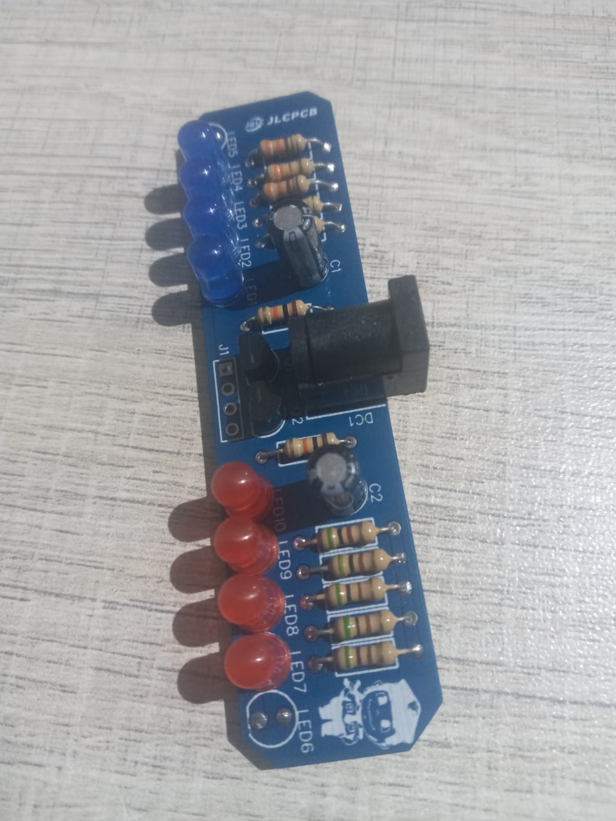
ELECTRONIC COMPONENTS
- 5 LEDS DIODES 5MM RED
- 5 LEDS DIODES 5MM BLUE
- 1 JACK DC
- 5 RESISTORS 500ohms 1/4w
- 5 RESISTORS 330ohms 1/4w
- 2 RESISTORS 10K 1/4W
- 2 TRANSISTORES 2N2222A
- 2 CAPACITORS ELECTROLITOS 100UF16V
- 1 PCB
TECHNICAL CHARACTERISTICS
- VIN 12VDC
- IMAX 100mA
- POLICE LIGHTS
- VARIABLE FREQUENCY
- EFFICIENT AND COMPACT
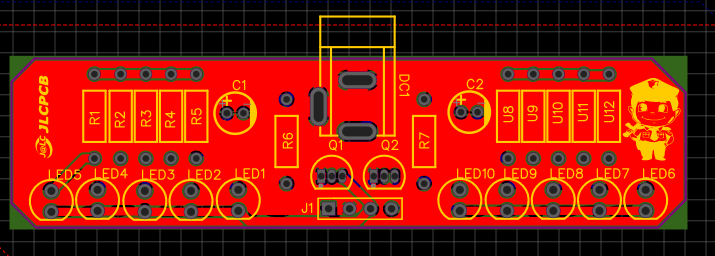
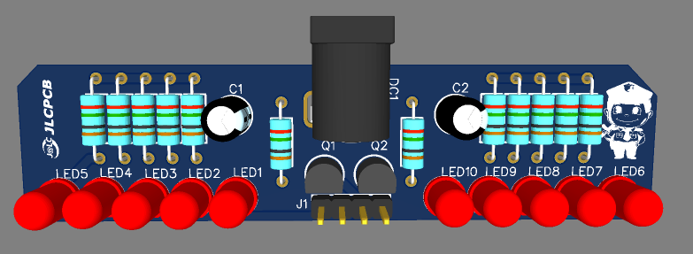
EASYEDA
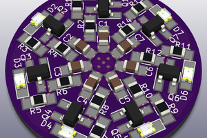
Once the project is finished with all the respective tests, we carry out the PCB design and we will obtain the routed tracks and the 3D image of how our finished PCB would look.
JLCPCB
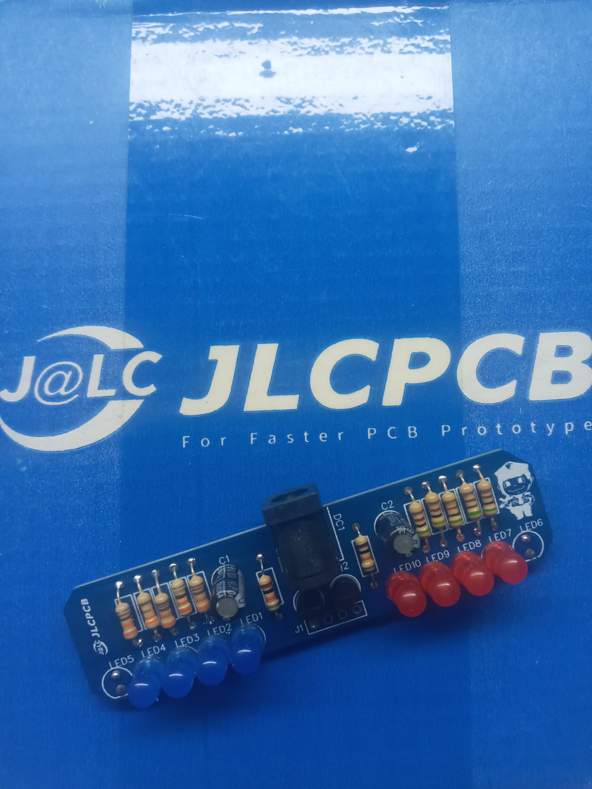
Once the pcb is designed, we will send our friends from JLCPCB to manufacture our PCB.
5pcbs only $2
JLCPCB number 1 PCB manufacturing company worldwide professional pcbs and excellent finish.
GERBER PCB:
https://mega.nz/file/zZ5hmRSa#dQFUK1ZjS5RdYPjYKaGl5hNydDziKjKeKmunMRPJ75U
you can get your pcbs in different sizes and colors.
 Mrinnovative
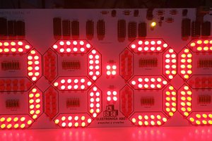
 marble
 Chris
Chris