Introduction
For this challenge, I've designed a simple two tone alarm. Both tones are tunable through potentiometers.
Circuit Theory of Operation
The circuit consists of two oscillators: the slower set frequency oscillator, which switches between the two tones, and the higher frequency oscillator, whose frequency is tunable through a voltage signal.
The slower oscillator is a relaxation oscillator (shown below).
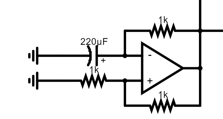
The relaxation oscillator is a comparator circuit, but we prevent it from comparing to the output instantly by adding a capacitor to slow the change in voltage. This allows us to have an oscillating square wave.
The higher frequency oscillator voltage controlled oscillator (shown below)
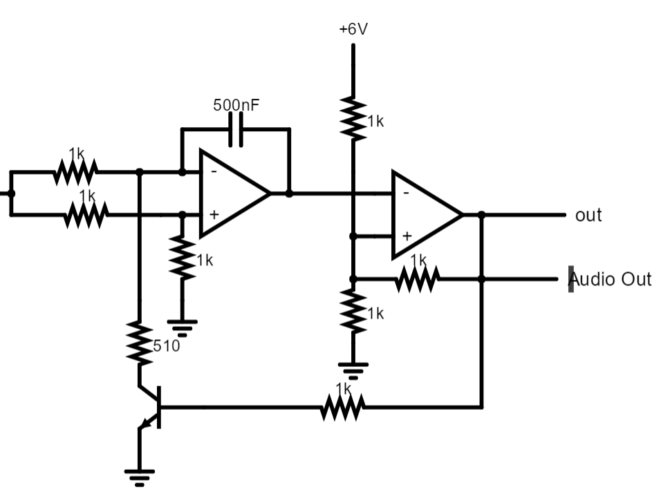
The second op amp in the diagram is a comparator to a set voltage, made by the voltage divider. This op amp will change its voltage based upon if the voltage from the relaxation oscillator is above 3V or below 3V. When above 3V, the op amp turns on, allowing current to flow through the BJT Transistor. This drains the capacitor, until it is below 3V. Having more voltage at the input of the first stage allows the capacitor to charge faster, and therefore allows a higher frequency wave to be output. Having less voltage has the opposite effect.
To connect these two stages together, we modify a CMOS NOT gate:

This NOT gate allows us to choose the voltage that goes to the high frequency stage. It's input is the low frequency relaxation oscillator. Because of this gate, whenever the relaxation oscillator's output is low, we output one tone, and whenever it is high, we output another tone. This goes on for infinity.
Circuit Design and Construction
For the final circuit, the following diagram was used:
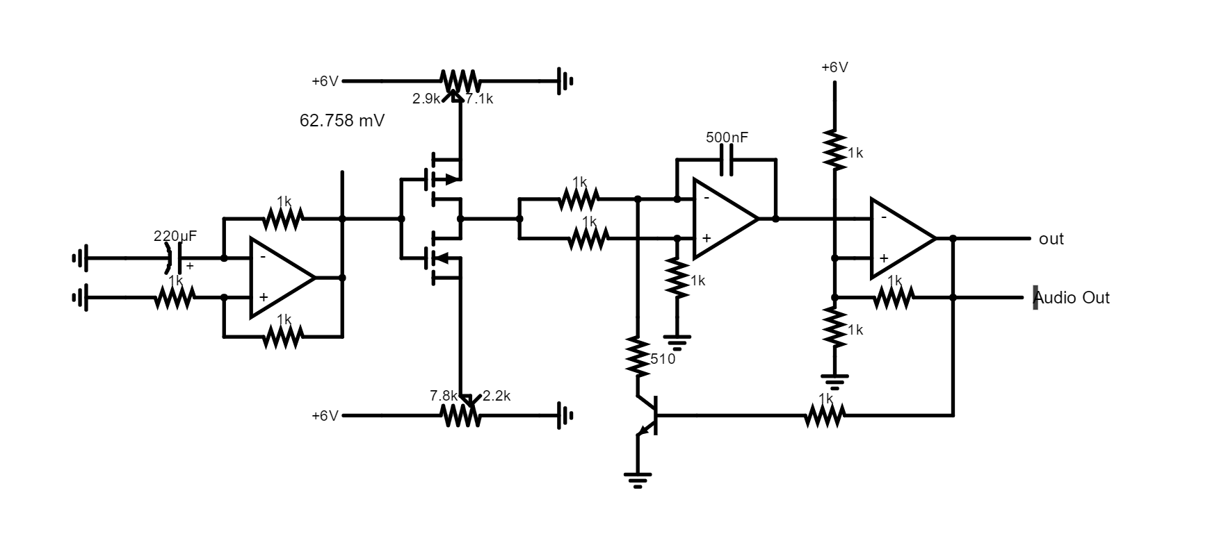
Just as a note, the only op amp that required negative voltage was the first one for the relaxation amplifier. This allowed the capacitor to drain faster and allowed a duty cycle closer to 50%. The circuit was designed in CircuitJS1, and the final file can be found in the "Files" section. The simulation also records the tone, so let it run for a bit (or crank up the simulation speed on a beefier computer) and play the audio tone to hear what tones we should expect.
A list of components used is provided below, quantities in parenthesis:
- LM358 Dual Operational Amplifiers (2)
- 2N2222 NPN Transistor (1)
- TP2104 PMOS Transistor (1)
- BS170 NMOS Transistor (1)
- 220uF 25V Rated Electrolytic Capacitor (1)
- 1 uF Capacitor (2)
- Placed in series to make 500nF
- 10kΩ Potentiometer (2)
- Piezo Buzzer (1)
- Pulled from some scrap electronics years ago.
- 1kΩ Resistor (9)
- 510Ω Resistor (1)
- Breadboard (1)
- Jumper Cables
A list of the tools used to power and help with circuit construction is shown below:
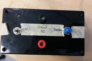
- Power supply with Built-In Function Generator
- Just wanted to note that one of the professors at my alma mater university had designed, had a company help manufacture, and distributed the power supply to all of the students in (I think) the Fall of 2020, just so we could have a lab at home to go along with the course. The original plan was to give them back end of the semester, but he surprised us by convincing the school to let us keep the power supplies. I still use that power supply to this day, and just wanted to say thanks.
- Basic Oscilloscope
- Same story as above
- 6V Batteries (2)
- Needlenose pliers with wire cutters
- Wire Strippers
- Multi-Meter
- LCR Meter
- Screwdriver
- Used to adjust the potentiometers.
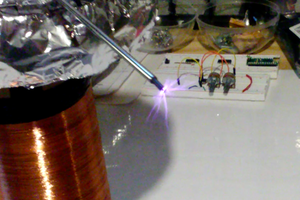
I followed along with the circuit diagram, highlighting components as I placed them, and came out with this circuit:

The red, black, and white wires going out of the board are VCC+, GND, and VCC-, respectively.
Testing the Circuit
After the circuit was built, it was time for the moment of truth. I connected the wires to their appropriate terminals, and after some fiddling and waiting, it started to work... [Video]
Until it didn't...
To be honest, I don't know exactly why the pitch goes down then goes silent near the end of the...
Read more »
 Sebastian
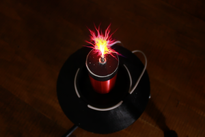
 Zach Armstrong
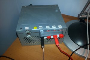
 Ellie T
Why such a large capacitor on the relaxation oscillator? Opamp inputs are high-Z so you could reduce the C to 0.22u and raise the R to 1M and retain the same RC constant. Ditto for the other input, you could raise the Rs and reduce current flow.