Close
0%
0%

Raspberry Pi Garage Door interface

Control and monitor a garage door opener with HomeBridge

Similar projects worth following
Typical home automation setups for garage door openers involve being able to trigger the opener to operate and sense the door position. This project provides a simple interface to allow a Raspberry Pi to do both.

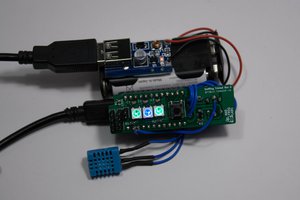
HomeBridge has a plugin for simple relay-plus-sensor configurations like this. One GPIO pin is a relay trigger and the other is a sensor pin.

It's important to insure that the Pi is isolated from from the opener. To that end, a reed relay controlled by an N MOSFET is sufficient for a garage door button.

A typical magnetic sensor is a switch closing, not unlike a relay. While it's sufficient to simply use a pull-up and switch it against ground, it's slightly safer to do something like MIDI - set up an opto isolator to capture the switch closing and translate that into a logic level for the Pi.

On the software side, I've used HomeBridge to talk to the service behind a Chamberlain gateway, and that works pretty well (EDIT: well, it did until this week. Check out the logs). Our new home comes with a Genie garage door opener, and I was considering buying their Aladdin internet connection gizmo. The problem with that, though, is that it's essentially a relay and a sensor. So it's really not any better than just doing it this way, but you're paying extra and adding an extra Internet layer for little gain.

Adobe Portable Document Format - 36.65 kB - 06/09/2023 at 21:37

Preview
Download

sch - 215.49 kB - 06/09/2023 at 21:37

Download

brd - 67.02 kB - 06/09/2023 at 21:37

Download

Adobe Portable Document Format - 31.00 kB - 06/09/2023 at 21:37

Preview
Download

sch - 158.98 kB - 06/09/2023 at 21:37

Download

View all 6 files

  • Hackaday Home Automation Project Contest

    Nick Sayer02/28/2024 at 17:56 0 comments

    I've gone ahead and entered this in the current Home Automation contest.

    I don't have a whole lot of expectations here; this project is extremely simple, and partly relies on the work of others to be complete.

    But the thing about Home Automation is that getting stuff to just work is actually quite rare. And I've done a whole lot of HomeKit stuff, and it turns out that this particular garage door integration is one of the most reliable things I've done so far. So that ought to count for something.

  • Chamberlain/Liftmaster

    Nick Sayer10/24/2023 at 23:50 0 comments

    Until now I had been using the MyQ homebridge plugin with a MyQ gateway to control our relatively old (but still working just fine) Liftmaster opener. But now that Chamberlain is being assholes about MyQ API access it looks like the future for that is not looking great.

    Chamberlain/Liftmaster openers fit into two broad categories: Older openers will respond to a dry contact relay closure to operate the door. Ours is one of those, and that means that this board will work just fine. Alas, newer openers won't respond to a relay closure anymore. Instead, there is a proprietary rolling-code serial protocol on the wire from the wall button. For those, the prospect of third-party control is much grimmer. There is this little project... and the good news is that unlike the Internet MyQ API they can't try to update the wire protocol to thwart hackers.

  • Repurposed

    Nick Sayer07/30/2023 at 04:28 0 comments

    Turns out that I need to add a doorbell to the back door of our house and want it to just be a HomeKit doorbell. You can certainly buy HomeKit doorbells, but they invariably are camera doorbells, and in this case we don't need that. Well, there's a HomeBridge plugin that can turn a GPIO pin into a HomeKit doorbell input, and I had a spare Pi Zero and one of these boards, so I've used the sensor side of the board for this. It works just fine, and if I can come up with a use for the relay later, well, it'll be there.

  • First build report, part 2

    Nick Sayer06/12/2023 at 18:33 0 comments

    The opts came this morning, and they work. The way the circuit works, the input sense is backwards - closing the sensor input sets GPIO18 to 0 and opening it sets it to 1. But that's fine.

  • First build report

    Nick Sayer06/09/2023 at 23:19 0 comments

    Before I ordered the boards, I actually updated the schematic and board a little bit.

    1. I added a 10 µF cap on the 5 volt rail to help with any potential inrush current needed by the relay.
    2. I added a flyback diode parallel to the coil to protect the transistor (you can get reed relays with built-in flyback diodes, but I didn't manage to do that).
    3. I moved the opto slightly further away from the sensor jack footprint.

    The results of that are schematic and board set 1 in the Files section.

    Unfortunately, the optoisolator footprint I chose was not a match for the optoisolators I have on hand, so I've had to order a suitable part and it won't be here until after the weekend. But the relay portion of the project does work: Setting GPIO 17 high closes the relay and releasing it opens it.

    While the boards were being fabbed, I made a second version of the project. This one takes 12 volts in via a 2.1mm barrel connector and includes a 2A 5v power supply for the pi as well as using 12 volts as the supply for the opto diode (with a corresponding increase in the resistance of the series resistor). I'm probably just going to use a USB power brick as I have a ton of them, but it's an option.

  • Door sensor

    Nick Sayer06/05/2023 at 20:34 0 comments

    As a reminder, this project is two pieces: a relay closing across the door button to open or close it, and a sensor to determine whether the door is closed or not.

    Well, here's a sensor to do the latter. It's a heavy duty magnet sensor you anchor to the garage floor, and a frame you attach to the door to hold a magnet. This will close the sensor switch when the door is closed. The result of that will be the optoisolator being lit and the transistor conducting, which will pull the GPIO pin low.

  • More isolation

    Nick Sayer05/30/2023 at 13:55 0 comments

    While there is an optoisolator for the sensor input, the LED inside it is powered by the Pi's 5 volt supply. One could make the argument that that is not full isolation. The purpose of such isolation is to protect the Pi's GPIO pins from any potential abuse due to any stray current (from whatever source) showing up on the wiring of the sensor.

    If, say, someone connected line voltage inadvertently to one of the sensor lines, the result would either be blowing out the optoisolator LED or energizing the Pi's ground. Given that the Pi's power supply itself is very likely an isolated flyback topology, the latter scenario, while dangerous to personnel, is less likely to be damaging to the Pi itself, unless perhaps the entire thing becomes a high current path from the HV source to ground.

    The solution to this would be an isolated DC-DC converter module to create an independent and isolated 5 volt supply just for the opto. This is certainly doable, I am just not convinced that it's worth the extra cost (though you could make similar arguments about the opto itself).

    Another potential argument in favor of doing that sort of thing would be if 5 volts wasn't enough voltage for a potential long length of sensor wiring. There's no reason the DC-DC converter couldn't have a different output voltage - say 12 volts. You could then replace the series resistor with a 20 mA current regulator instead. In that universe, you could imagine the sensor having 500 Ω of impedance in the closed state and the circuit would still work (instead of, perhaps, a maximum of 100 Ω or so). But in the context of a garage door controller, it's hard to imagine this being an issue.

View all 7 project logs

Enjoy this project?

Share

Discussions

Similar Projects

Does this project spark your interest?

Become a member to follow this project and never miss any updates