 CJ
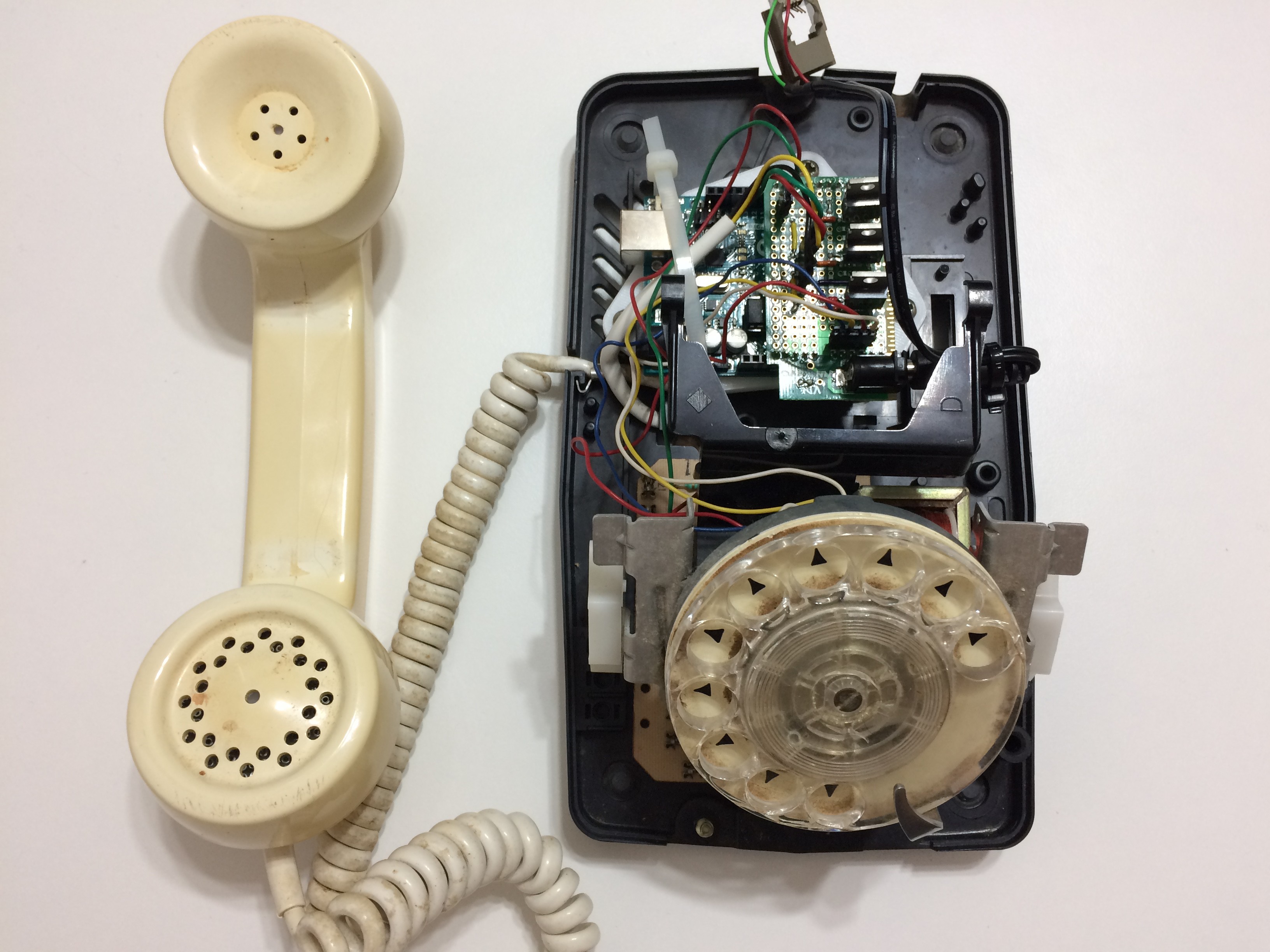
CJSome very good friends gave me an old rotary phone as a gift. Not exactly sure what they thought I would do with it, but it's pretty cool so I made a point to think of something.
A 360º color wheel is cut into twenty 18º pieces. With the handset on the hook, you can dial to any of the even-numbered colors. Take the phone off the hook and you can dial odd-numbered colors. After 5 minutes of inactivity, the color dims to zero and the phone looks completely normal. Except for being about 30 years out-of-place.
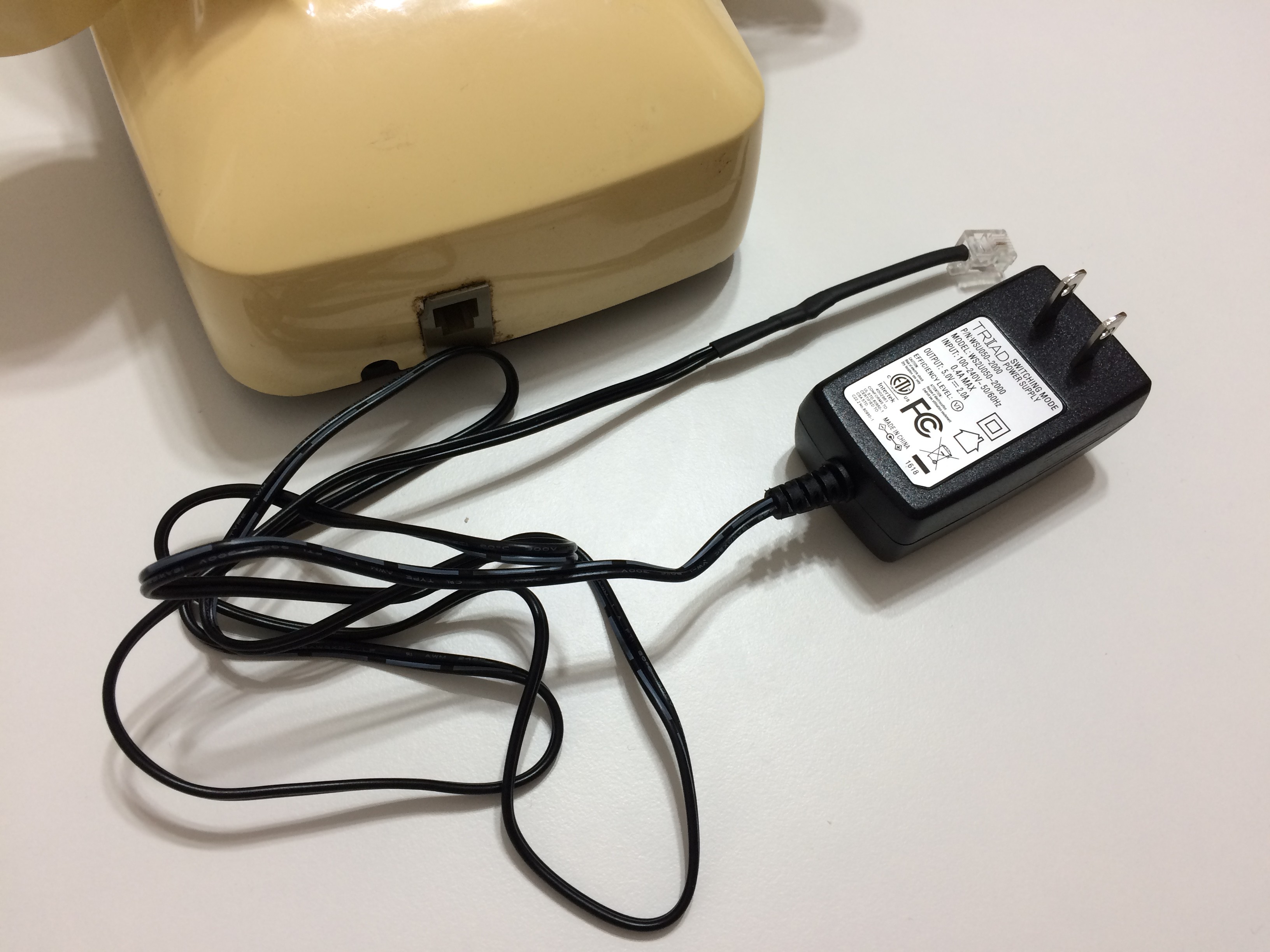
Chopped off the barrel-end of a 5V 10W wall supply. Reterminated it with a phone jack from the cable that came with the phone. This is how power gets in.
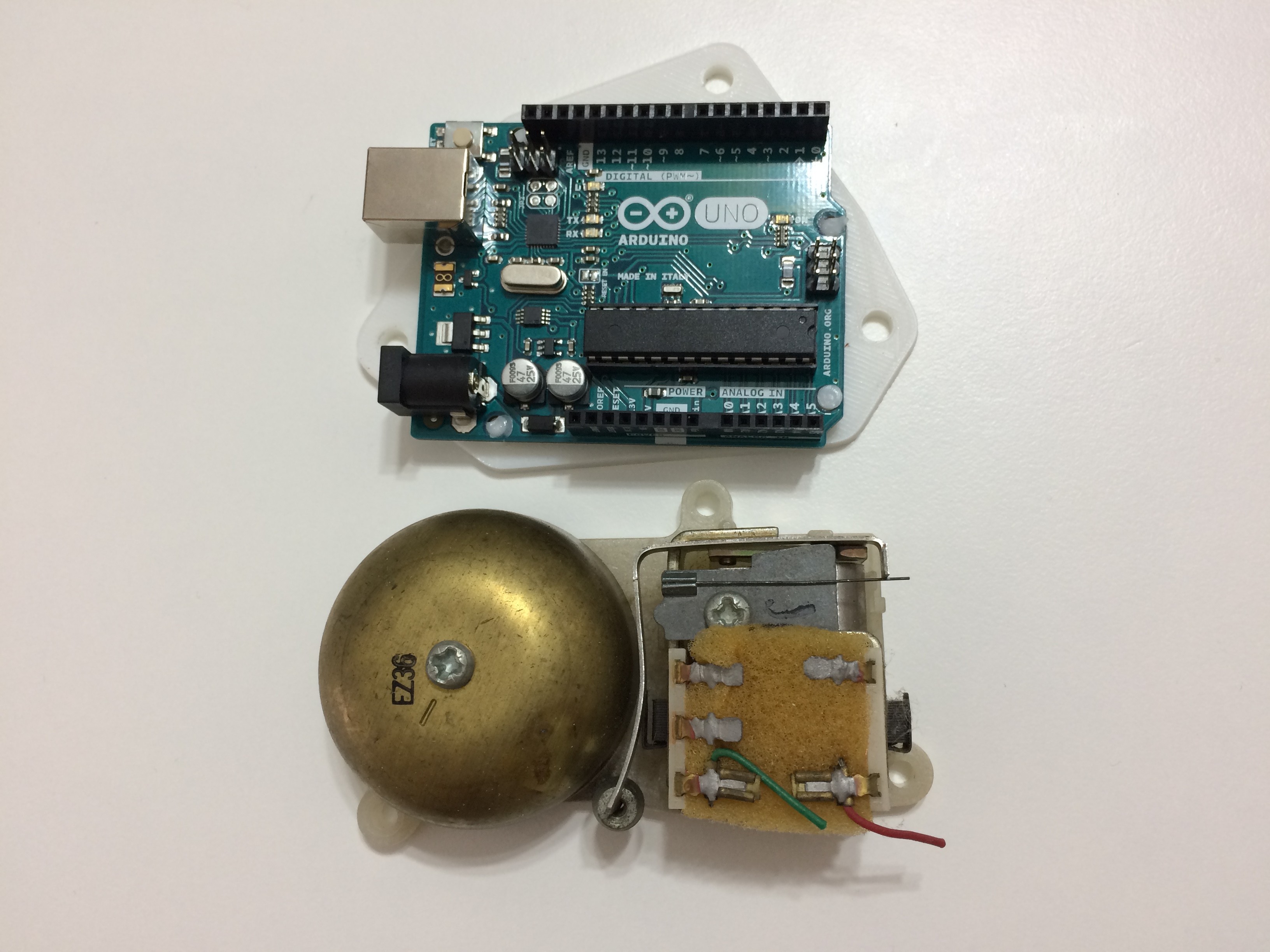
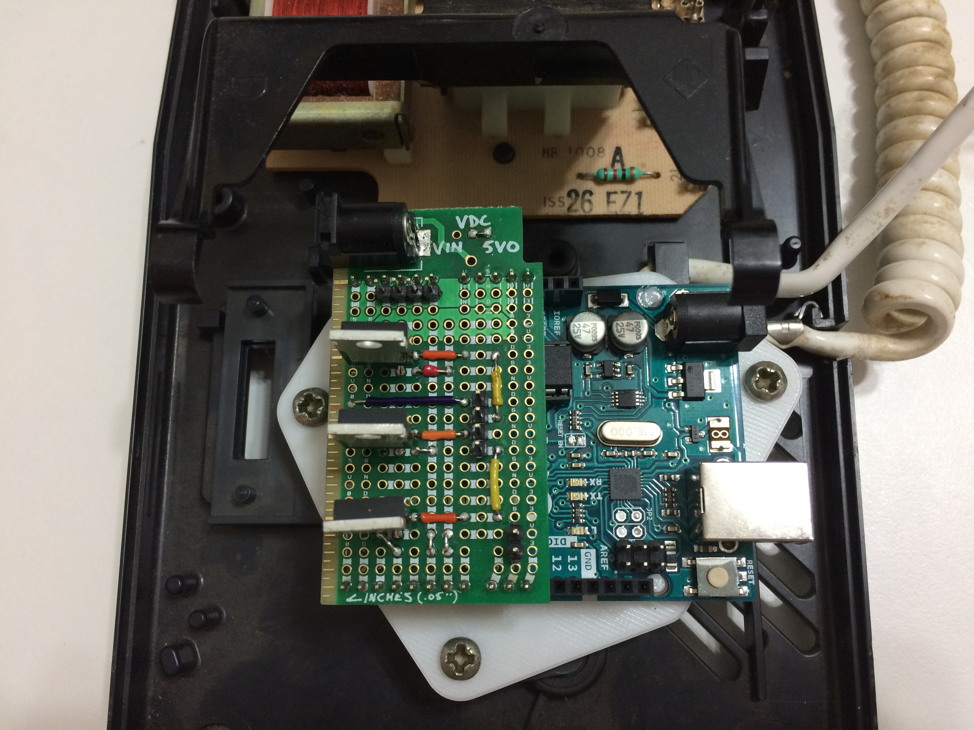
The old bell-ringer assembly is about the size of an Arduino UNO. Designed a 3D-printed plate to allow one to mount to the same hole pattern, and with the original screws.
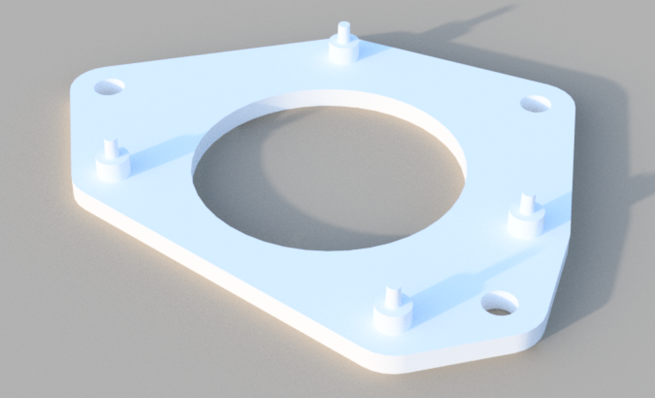
Arduino UNO heat-stakes to the PLA adapter plate.
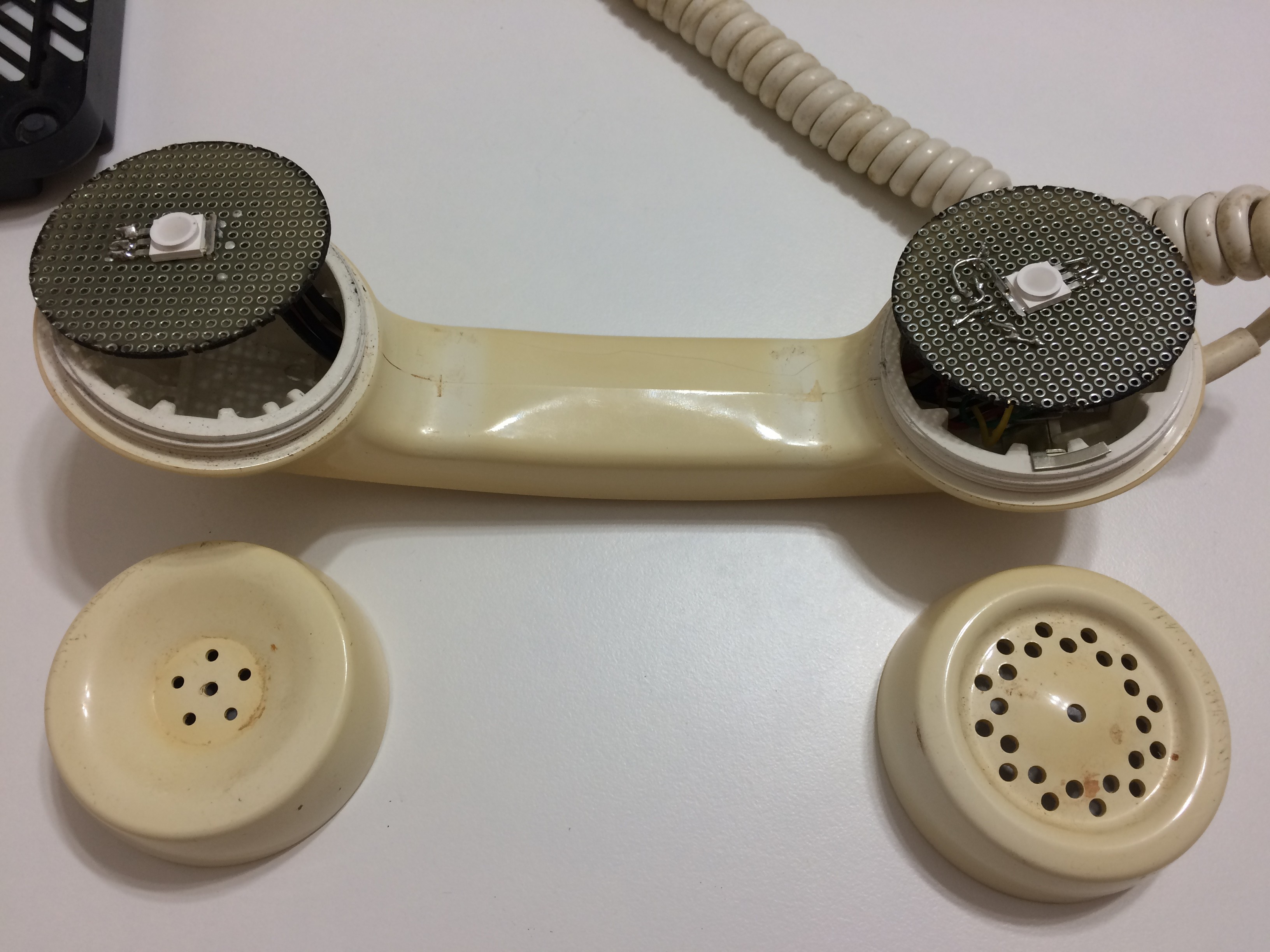
A single high-brightness common-anode RGB LED mounts in the center of a laser-cut disc of perfboard in each side of the handset. Screw-on caps retain the discs perfectly.
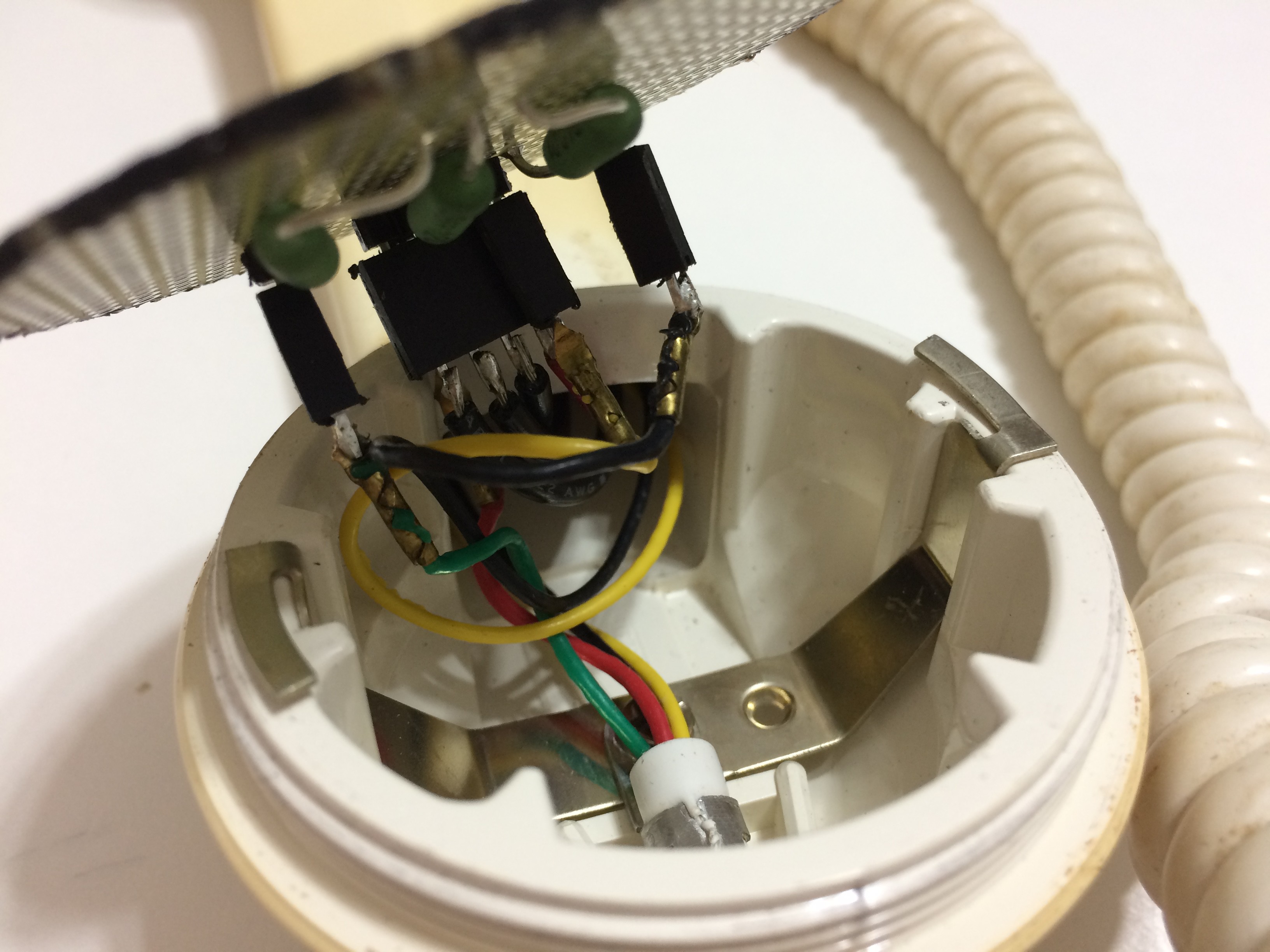
Each LED has a bias resistor, selected to equalize brightness to 5 lumens across all colors. Metal clip on original spiral handset cable screws into flange in handset for strain relief.
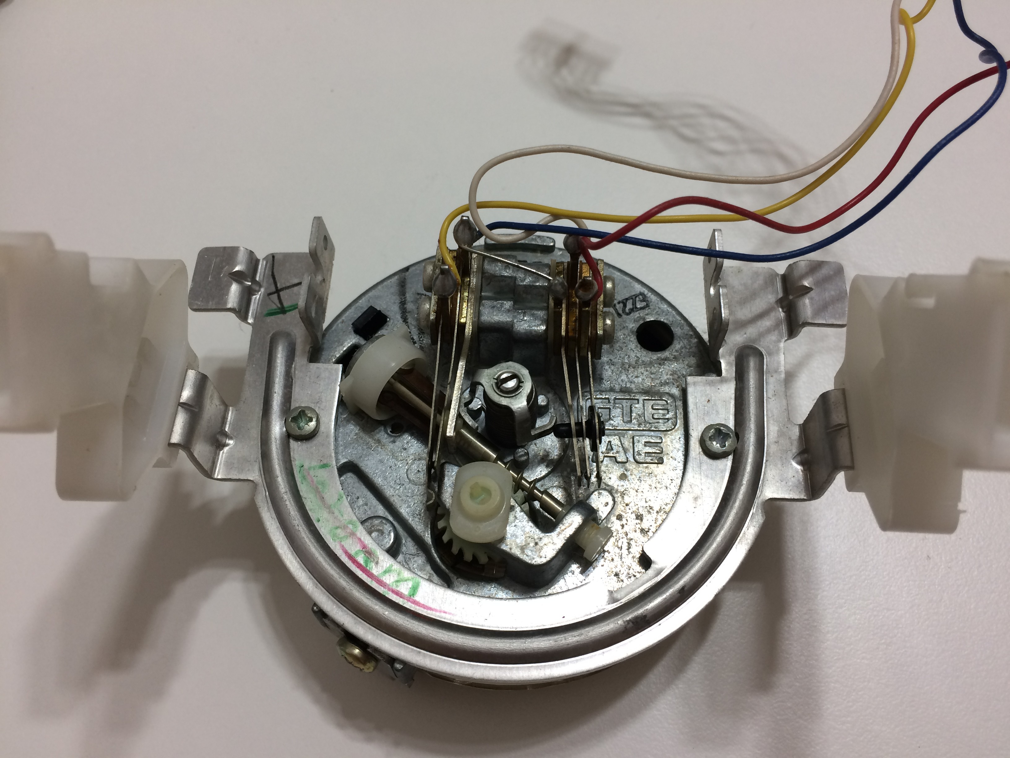
Reverse of rotary assembly, showing contact tines. It's just switches, so playing with it and watching carefully is all you need to figure out how to integrate it into a new system. Amazing that it still works after all these years.
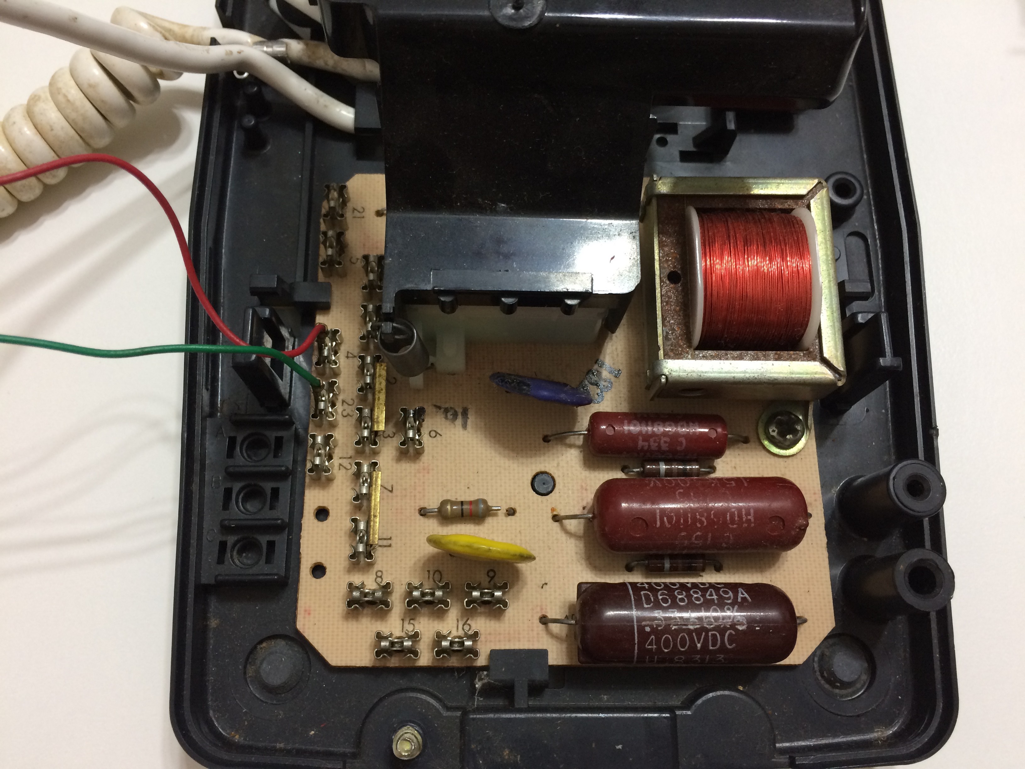
Original PCB for the phone, now completely disconnected except terminals 4 and 23, which go to the hookswitch. This PCB sits under the rotary assembly, which has been removed.
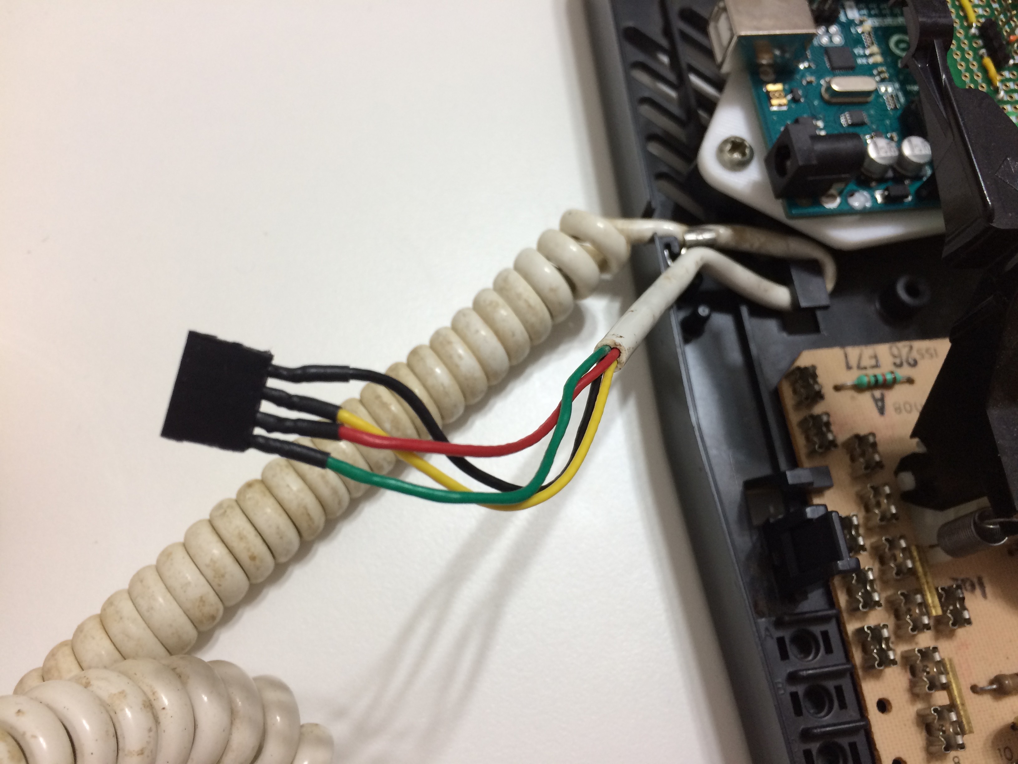
Original spiral cable reterminated to a header. Four pins are Anode (5V) and R, G, B cathodes (after bias resistors.) The conductors in this cable are very fine to make them durable for flexing, so the solder joints to the header are reinforced with heatshrink.
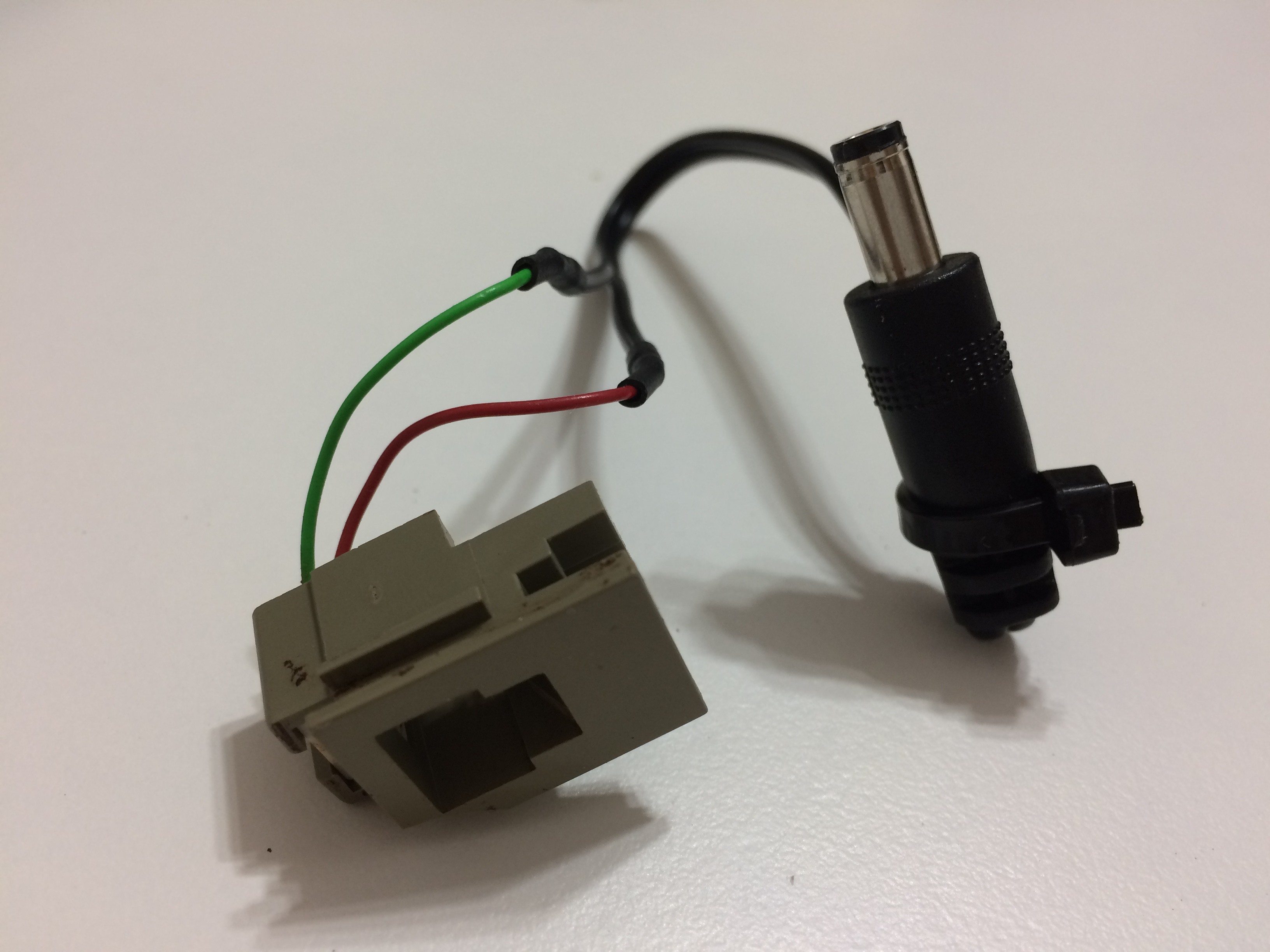
The "inside" of the phone jack connector is reterminated with the barrel jack I previously cut off the DC adapter.
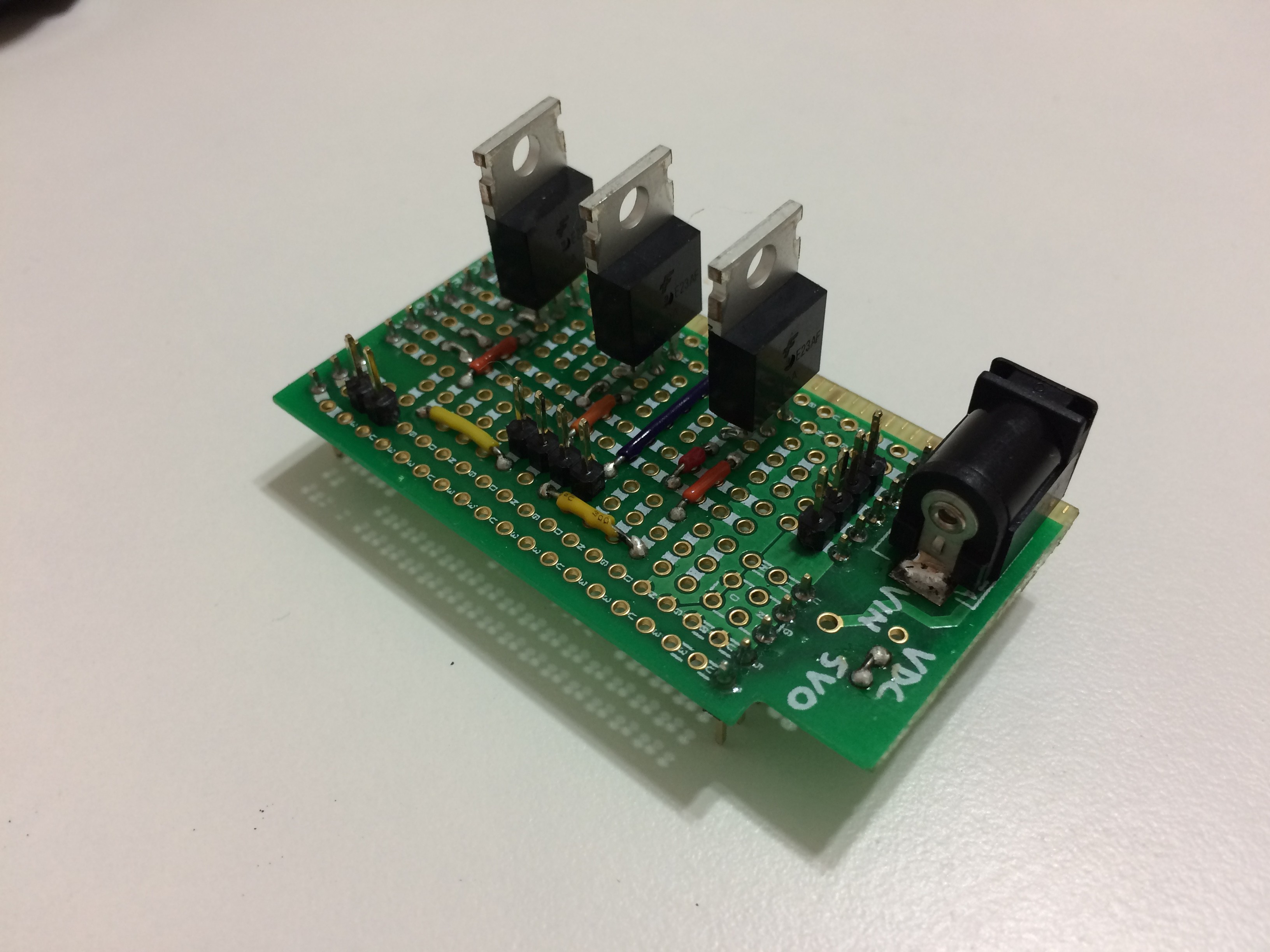
Arduino shield constructed for this project. 3 MOSFETs, one to PWM each color channel. Four connectors, from left-to-right:
- 2-pin: Hookswitch connector
- 4-pin: Handset LED connector
- 4-pin: Rotary input connector
- 5.5mm Barrel: 5V0 power input, goes to shield and UNO below
All wiring and components on top side, nothing underneath except headers to plug into UNO. Perfboard is from a SCALAR Electronics Multitool (https://www.tindie.com/products/SCALARElectric/prototyping-multitool/)
PLUG: Get them for $1/apiece (50% off) from my store by using discount code HACKADAY. Congrats for making it this far in my post :)
 CriptasticHacker
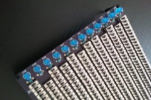
 Arduino Enigma
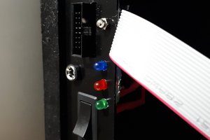
 Neil Mundt
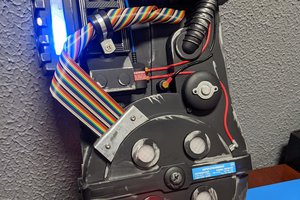
 Tom Nardi