Close
0%
0%

Bringing up a new Betaflight target: STM32H725/735

Betaflight doesn't support the H725 yet, but we have hardware with that chip. Let's try to create a new target, and take notes on the way.

Similar projects worth following
Betaflight is a firmware for quadcopters that already supports many different MCUs. We designed some flight controllers based on the H725 (because it was available when we were shipping for a main MCU just when chip shortage started to become a real problem), but unfortunately betaflight doesn't support that chip. Yet.

In this project I'll document the steps taken to understand betaflight's low level code, how it's compiled and linked, and how to adapt it for a new MCU. In this case the MCU family is already part of betaflight's code, so the work shouldn't be too monumental. If it was a completely new architecture (such as PSoC6 or something like that), that would be different.

The goal of this project is to create a new target (STM32H725/H735) for betaflight (BF), using an existing target as a template, and to document the process on the way for future devs who want to do similar contributions.

For a new target in BF, we need

  1. Working hardware to play with
  2. some template for the code
    1. linker scripts
    2. startup code
  3. a BF-compatible linker script
  4. BF-compatible startup code
  5. Adjustments to peripheral setup and usage, if required
  6. Tons of patience along the way
  7. Support from the BF devs; platform of choice is discord

1 - Working Hardware

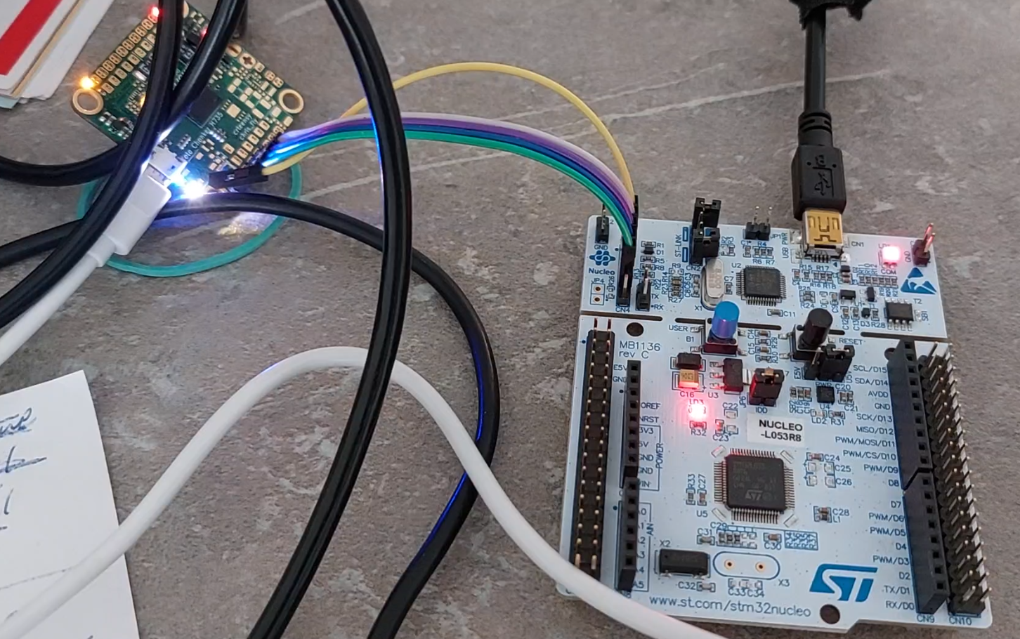
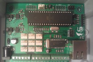
We have the "Chonker" (see project links), a custom PCB with the target MCU on it. It also features footprints for various peripherals usually found on a quadcopter (IMU, Barometer, Flash, LEDs) but most of that is not populated. There's an SWD header for debugging and a nucleo board that brings an ST-Link programmer/debugger to the table:

2 - Template

Since the H725/H735 target might be similar to an existing target from the H7 family, let's start with the H743 and see what we can use and how it might align with the H725.

3 and 4 - Linker script and Startup code

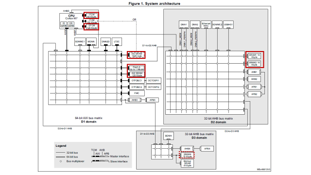
The Linker script tells the linker what memory areas exist on the MCU (different flavors of flash and RAM, their addresses and sizes) and what data goes where (executable code to flash, variables to RAM, initialization data to flash again, and so on).

The startup code is what is executed before entering main() and is highly MCU- and also application-specific. We'll have to find out what preconditions must be created before entering main so that the actual application can run on the properly prepared system. This includes initialization of power supplies, clock forest, and initialized variables.

We'll use the H743 linker scripts and startup code as a general guidance.

5 - Peripheral setup and usage

I expect this to be tricky - it's hard to tell what exactly BF expects here, but let's relax. It'll be a long way until we actually get to this point.

6 and 7 - Patience and Support

Since we're working on a new target, some Chonker boards were sent out to selected BF devs to support this project. However, that's not a "give hardware, receive code" trade. 

  • Picking template code: linker scripts

    Christoph06/05/2023 at 07:05 0 comments

    Adding a new target to BF shouldn't be too hard if the new target is similar to an already existing target - right? Let's see what we have

    • STM32H743: a bit older
    • STM32H730: somewhat special, because:
      • This chip uses external memory to store the application
      • but it shares a reference manual with H723, H725, H733, and H735
    • STM32H723: as far as I know, this was just a draft and never actually worked.

    Let's take a closer look at the H743.

    Memory areas

    BF's H743 target uses a slightly customized layout that reserves flash for the reset handler and an emulated eeprom. Both BF and CubeIDE define areas in ITCM and DTCM for critical functions and data. Here's a table that compares BF's H743 memory areas with CubeIDE's H725/H735 standard:

    BF H743CubeIDE H725/H735                             
    FLASH (reset handler)FLASH
    FLASH_CONFIG (emulated EEPROM)
    FLASH1 (application and constants)
    ITCM_RAMITCMRAM
    DTCM_RAMDTCMRAM
    RAMRAM_D1
    D2_RAMRAM_D2
    MEMORY_B1 (*)RAM_D3 (**)

    *) external memory, can only be used if there's actually some external memory connected to the MCU

    **) not used by BF so we can hopefully remove that. Or not, since simply having a memory area in a linker script doesn't hurt.

    The BF linker script also defines two aliases:

    REGION_ALIAS("STACKRAM", DTCM_RAM)
    REGION_ALIAS("FASTRAM", DTCM_RAM) 

    The memory area names are a bit different between BF and CubeIDE but that's not a problem because these are only used within the linker script. A little understanding surely doesn't hurt so let's also have a look at the system architecture diagram for the H725. I've already marked the memories used:

    • Top left: ITCM and DTCM are tightly coupled with the core for fast access.
    • Center: Flash and SRAM in D1 domain via AXI
    • Right: SRAM1 and SRAM2 in D2 domain via AXI and D1-to-D2 AHB
    • Bottom: SRAM4 in D3 domain via AXI and D1-to-D3 AHB; not used by BF

    The two DMA blocks in D2 domain (DMA1 and DMA2) allow for fast transfers between memory and peripherals within that domain, and we see something similar for BDMA (basic DMA) in D3 domain. The MDMA controller also has access to blocks in D2 domain, but that's somewhat convoluted. So we do see why it make sense to deliberately place certain I/O buffers in D2 memory ("D2_RAM" or "RAM_D2" in the table above).

    Now we'd like to bring BF's memory areas over to the CubeIDE project. Turns out we can pretty much copy and paste them, as long as everything remains consistent within the linker script. A quick test reveals that the dev board still runs blinky after doing that. Great!

    Memory Sections

    The linker script further defines a number of memory sections. For plain old C we typically see

    • ".text" (instructions),
    • ".data" (initialized variables) and
    • ".bss" (uninitialized variables)

    But there's a lot more, because we need to place certain instructions in certain locations: reset handler and other ISRs need to be placed correctly in flash, and there has to be a section in ITCM that we can used to properly place functions that are supposed to be executed faster than others. Similarly, certain variables go into DTCM and I/O buffers into SRAM in D2 domain. And thus we end up with something like this:

    BF H743CubeIDE H735
    .isr_vector >FLASH.isr_vector >FLASH
    .text >FLASH1.text >FLASH
    .rodata >FLASH
    .tcm_code >ITCM_RAM AT >FLASH1
    .ARM.extab >FLASH1.ARM.extab >FLASH
    .ARM >FLASH1.ARM >FLASH
    .pg_registry >FLASH1
    .pg_resetdata >FLASH1
    .preinit_array >FLASH
    .init_array >FLASH
    .fini_array >FLASH
    .data >RAM AT >FLASH1.data >RAM_D1 AT >FLASH
    .bss >RAM.bss > RAM_D1
    .sram2 >RAM
    .fastram_data >FASTRAM AT >FLASH1
    .fastram_bss >FASTRAM
    .dmaram_data >RAM AT >FLASH1
    .dmaram_bss >RAM
    .DMA_RAM >RAM
    .DMA_RW_D2 >D2_RAM
    .DMA_RW_AXI >RAM
    .persistent_data >RAM
    ._user_heap_stack >STACKRAM = 0xa5._user_heap_stack >RAM_D1
    .memory_b1_text >MEMORY_B1

    Let's take a look at the similarities first: All "basic" sections have identical names (.isr_vector, .text,...

    Read more »

  • Working Hardware

    Christoph06/02/2023 at 21:55 0 comments

    We're working with the "Chonker H735" board which was developed solely for the purpose of bringing up the BF target.

    Repo: https://github.com/crteensy/yolo-chonker

    Several of these were built, some with just the base necessities like

    • MCU and optional 8 MHz resonator
    • USB connector
    • 3V3 regulator
    • two LEDs on GPIOs

    Writing basic blinky code in STM32CubeIDE won't get us the desired files we need for the BF target, but it's easy and provides us with:

    • some valid linker script
    • some valid startup code
    • a valid (limited) clock tree setup

    The main() function then might look like this:

    int main(void)
    {
      HAL_Init();
      SystemClock_Config();
      MX_GPIO_Init();
      while (1)
      {
    	HAL_Delay(500);
    	HAL_GPIO_TogglePin(led_blue_A10_GPIO_Port, led_blue_A10_Pin);
      }
    }

    There's not a lot we could remove from this. Some things to note though:

    • HAL_Init() is called first,
    • even before SystemClock_Config(),
    • and then we initialize the actual peripherals.

    However, there's a lot of stuff happening before main() is even entered: that's the startup code which includes the reset handler. It's written in assembler, but the first thing it does after setting up the stack pointer is to call SystemInit(), which is written in C again:

    startup_stm32h735vghx.s:

    Reset_Handler:
      ldr   sp, =_estack      /* set stack pointer */
    
    /* Call the clock system initialization function.*/
      bl  SystemInit
    ...

     system_stm32h7xx.c:

    void SystemInit (void)
    {
    #if defined (DATA_IN_D2_SRAM)
     __IO uint32_t tmpreg;
    #endif /* DATA_IN_D2_SRAM */
    ...

    SystemInit() configures things like FPU, Flash timing, available oscillators (there are a few of them, both internal and external), resets the PLL, and configures the interrupt vector table.

    After that, we're back in the asm startup code (startup_stm32h735vghx.s) with a bunch of snippets like this one:

    /* Copy the data segment initializers from flash to SRAM */
      ldr r0, =_sdata
      ldr r1, =_edata
      ldr r2, =_sidata
      movs r3, #0
      b LoopCopyDataInit
    
    CopyDataInit:
      ldr r4, [r2, r3]
      str r4, [r0, r3]
      adds r3, r3, #4
    
    LoopCopyDataInit:
      adds r4, r0, r3
      cmp r4, r1
      bcc CopyDataInit
    

    _sdata, _edata and _sidata are defined in the linker script. The snippet shown above copies data from flash to RAM. This data is used to initialize variables that were defined an initialized somewhere in the code, for example:

    static uint8_t foo = 3;

    The initialization value can only be stored in flash to survive a reset, but the variable itself resides in RAM during runtime - so the init code has to copy the init value to that RAM location during startup to prepare everything for the code that later relies on that variable to be properly initialized.

    There are other sections for variables that are initialized to zero, or not initialized at all. What we need to know now is what sections are generated by STM32CubeIDE, so that we can compare those sections with the sections in a linker script used in a working BF target. 

    Each of these sections has to be placed in some memory area (like flash, or RAM, and some sub-areas of those). These must be known and defined.

    CubeIDE's generated linker script (STM32H735VGHX_FLASH.ld) creates these memory areas:

    MEMORY
    {
      ITCMRAM (xrw)    : ORIGIN = 0x00000000,   LENGTH = 64K
      DTCMRAM (xrw)    : ORIGIN = 0x20000000,   LENGTH = 128K
      FLASH    (rx)    : ORIGIN = 0x08000000,   LENGTH = 1024K
      RAM_D1  (xrw)    : ORIGIN = 0x24000000,   LENGTH = 320K
      RAM_D2  (xrw)    : ORIGIN = 0x30000000,   LENGTH = 32K
      RAM_D3  (xrw)    : ORIGIN = 0x38000000,   LENGTH = 16K
    }

    and these sections:

    .isr_vector
    .text
    .rodata
    .ARM.extab
    .ARM
    .preinit_array
    .init_array
    .fini_array
    .data
    .bss
    ._user_heap_stack
    

     As written above, _sdata, _edata and _sidata are defined in the linker script. Here's the part that does that:

      /* used by the startup to initialize data */
      _sidata = LOADADDR(.data);
    
      /* Initialized data sections goes into RAM, load LMA copy after code */
      .data :
      {
        . = ALIGN(4);
        _sdata = .;        /* create a global symbol at data start */
        *(.data)           /* .data sections */
        *(.data*)          /* .data* sections */
     *(.RamFunc) /* .RamFunc...
    Read more »

View all 2 project logs

Enjoy this project?

Share

Discussions

Similar Projects

Does this project spark your interest?

Become a member to follow this project and never miss any updates