 ydrip
ydripFAQ
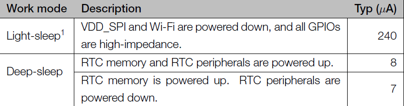
What problem does it solve?
YDrip primarily addresses the issue of costly water leaks and provides real-time usage information to help homeowners identify ways to conserve water. It can also assist municipalities in reducing consumption when deployed at scale, as population growth and changing climates continue to put a demand on water reserves. For example, Arizona recently implemented restrictions on new home construction as they face challenges related to declining groundwater levels.
How do most people deal with leaks and monitor usage today?
Many municipalities still rely on manual reading of meters by human operators. This means homeowners are charged based on estimates from past bills and only discover the actual cost 1-2 months later. By that time, a water leak could have already caused significant financial losses.
The minority of municipalities that have installed smart meters often lack effective leak notification systems. Their websites can be difficult to use, and reporting delays of hours or days are common. Additionally, profit incentives often don't align with conservation efforts, which is why some municipalities have started to decouple the profit motive.
Beyond leak detection, it is challenging to experiment with habit changes to reduce consumption without near real-time data.
What are the problems with existing solutions?
Existing commercial devices have various limitations:
- They often restrict access to your data through proprietary apps.
- Some require internet connectivity, turning what should be an appliance into a device with an expiration date tied to the company's lifespan.
- If data is accessible, it is often difficult to integrate it into other services.
- Some devices necessitate professional installation and can be expensive.
- The non-invasive solutions that do exist for reading water meters, there are few to none available for gas meter reading.
How does YDrip solve these limitations?
- The YDrip firmware is open source meaning you are free to use your data how you like. Opt-in hosted solutions will be available for those that want a turn-key solution.
- YDrip will always function without an internet connection on your local network.
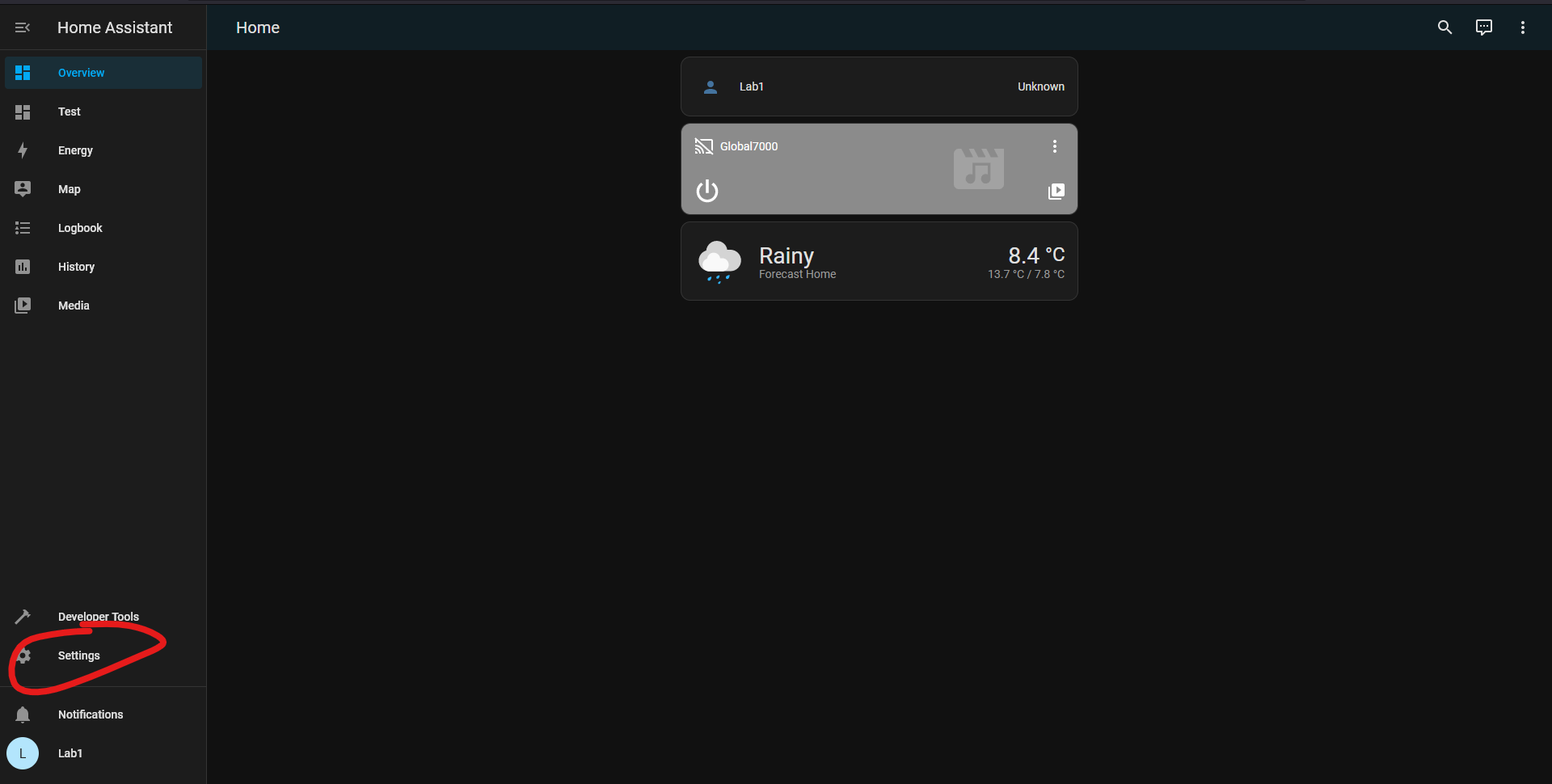
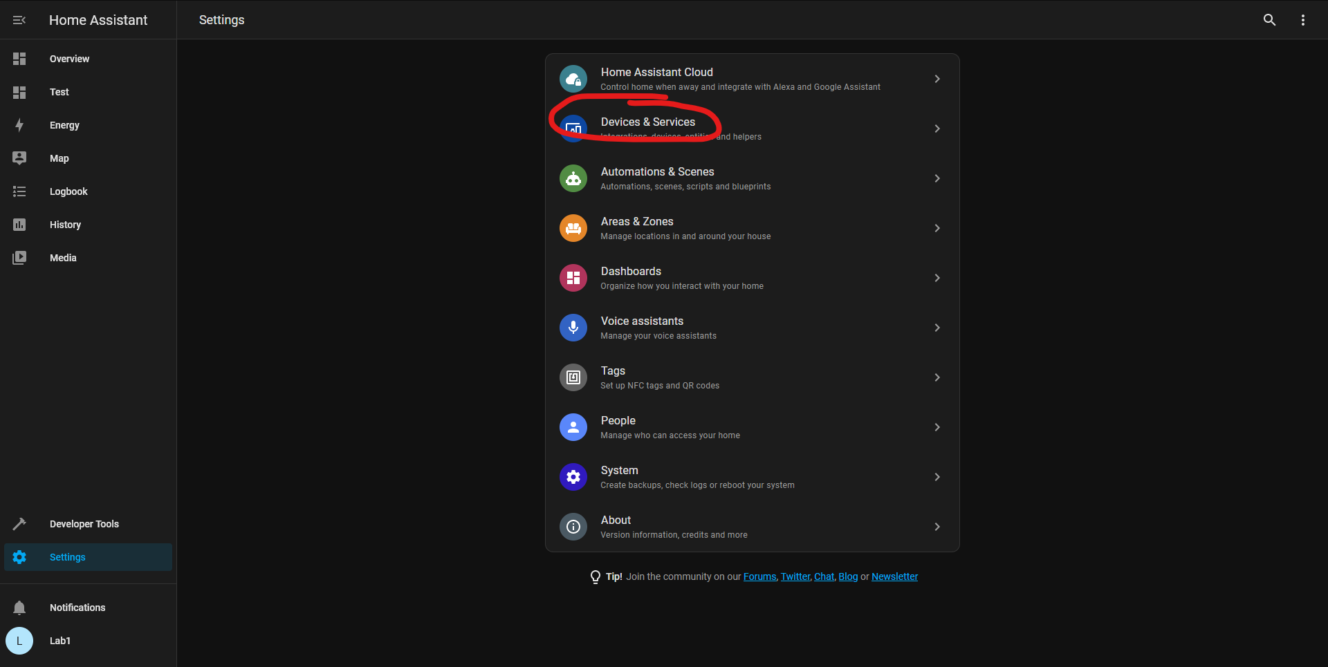
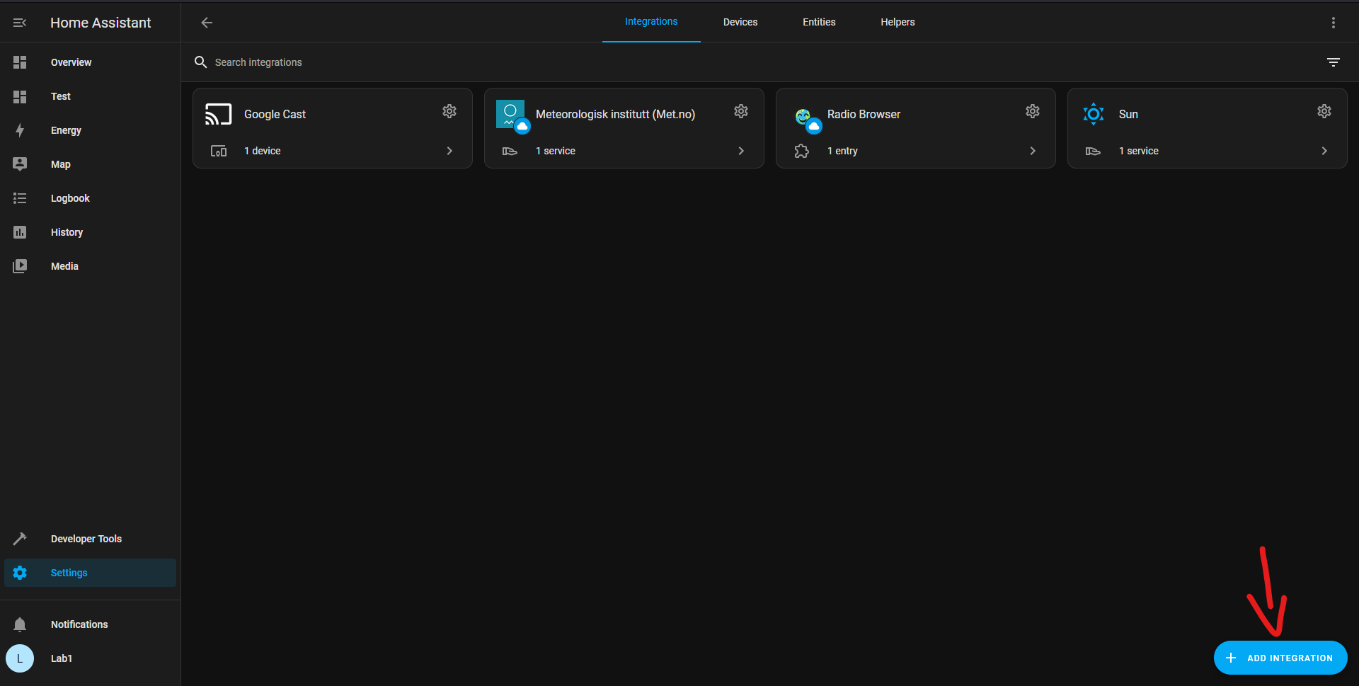
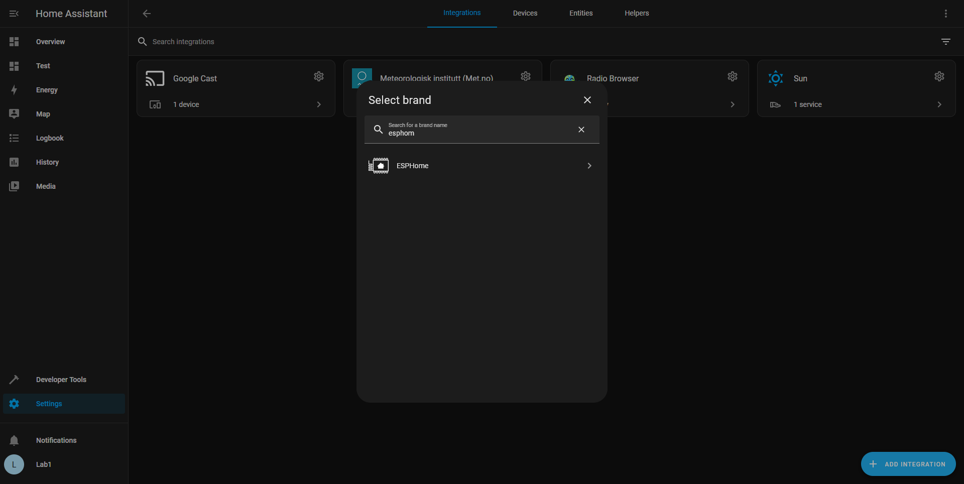
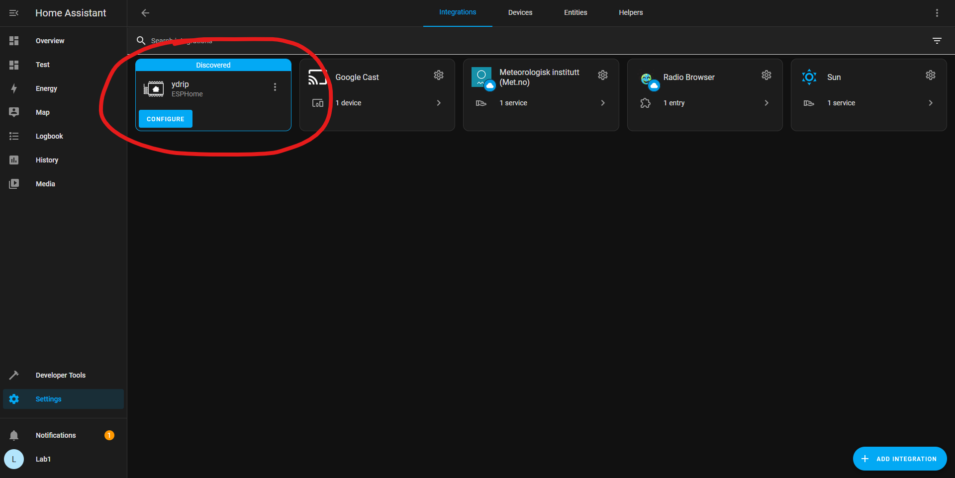
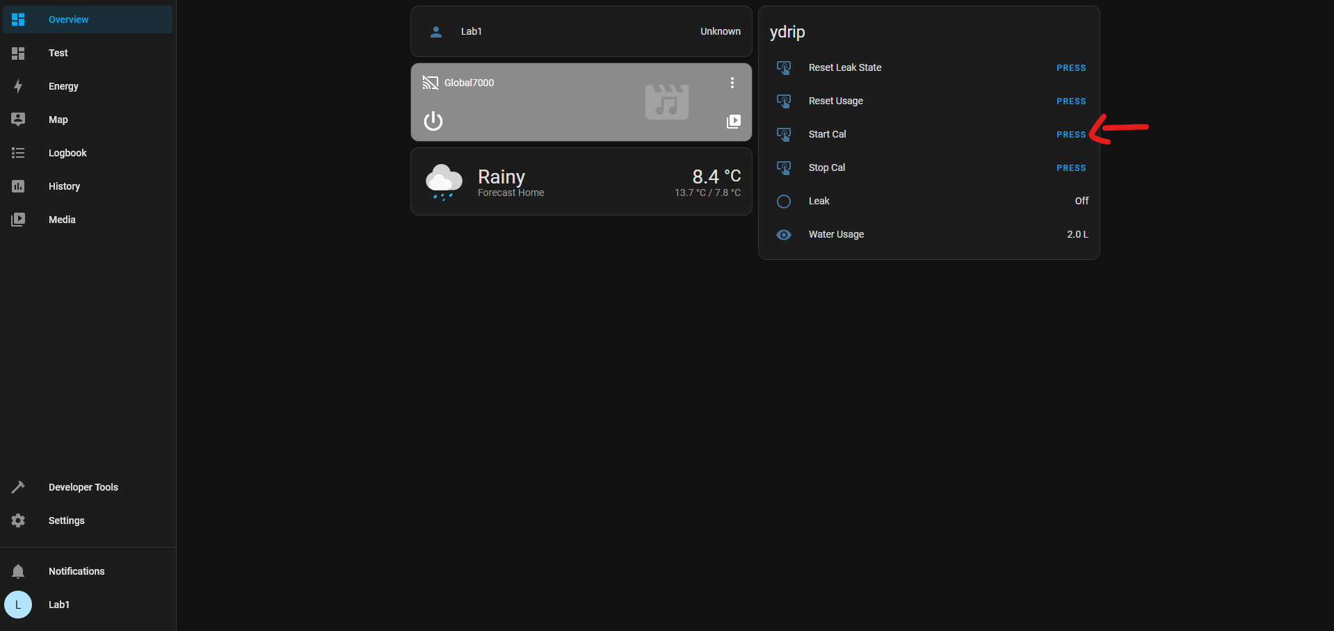
- ESPHome and Home Assistant compatibility will be supported at launch.
- The next version of YDrip will support non-smart mechanical gas meters without using light to read the dial which can be inaccurate and hard to install.
Requirements
YDrip shall:
- 🗹 be open source
- 🗹 be compatible with a wide range of water meters that have a rotating magnet mechanism
- 🗹 function without an internet connection
- 🗹 be wireless for remote monitoring of water usage and leak alerts
- 🗹 allow users to customize settings such as leak detection sensitivity and data transmission frequency
- 🗹 be compatible with popular home automation platforms, such as Home Assistant
- 🗹 be battery operated with a life span measured in months
- 🗹 send leak a notification as soon as one is detected
- 🗹 (in progress) low cost
- 🗹 (partial) include algorithms to detect abnormal water usage patterns that could indicate leaks or unusual consumption
- ☐ be waterproof and withstand outdoor temperatures
Current System Design
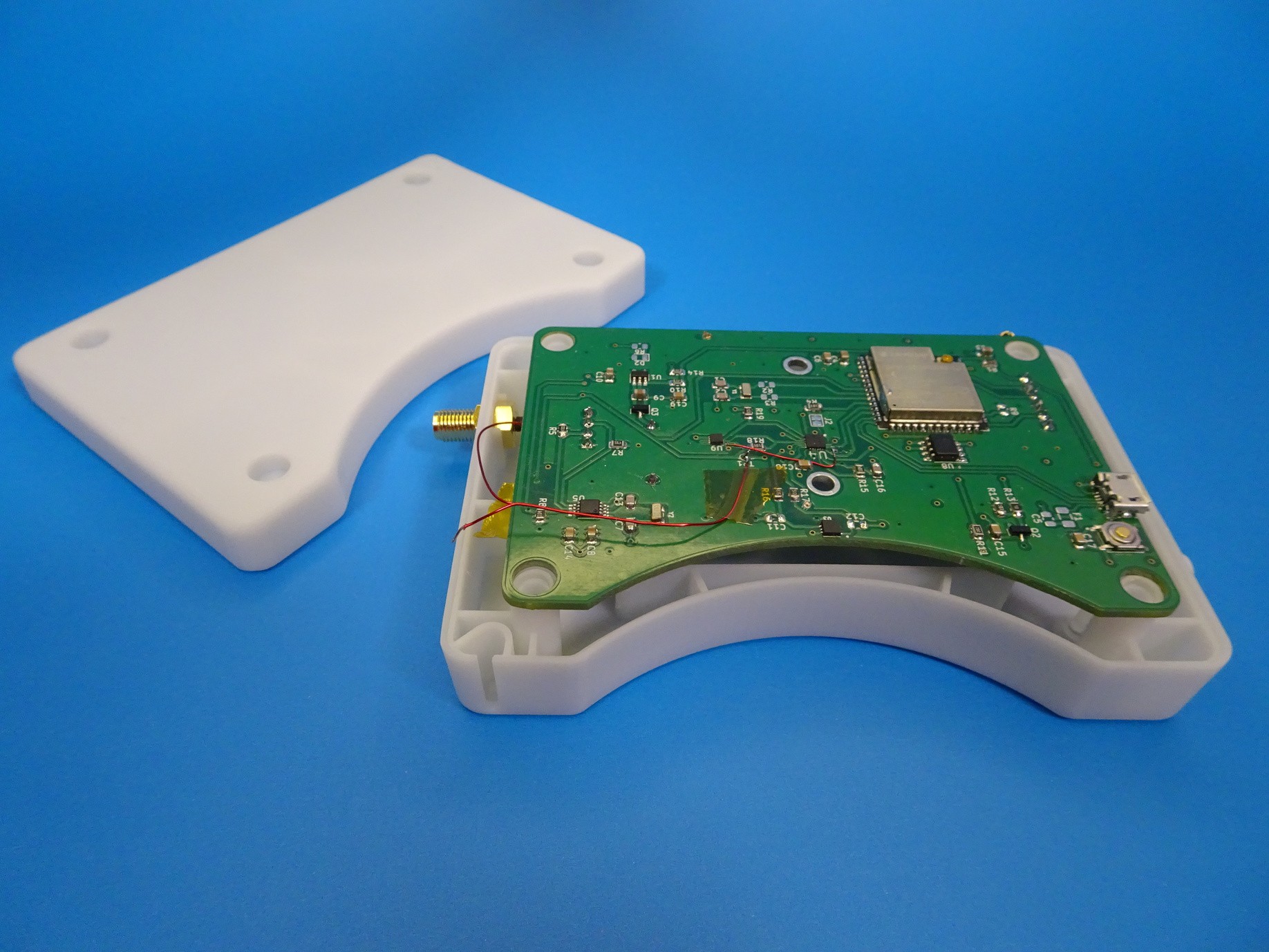
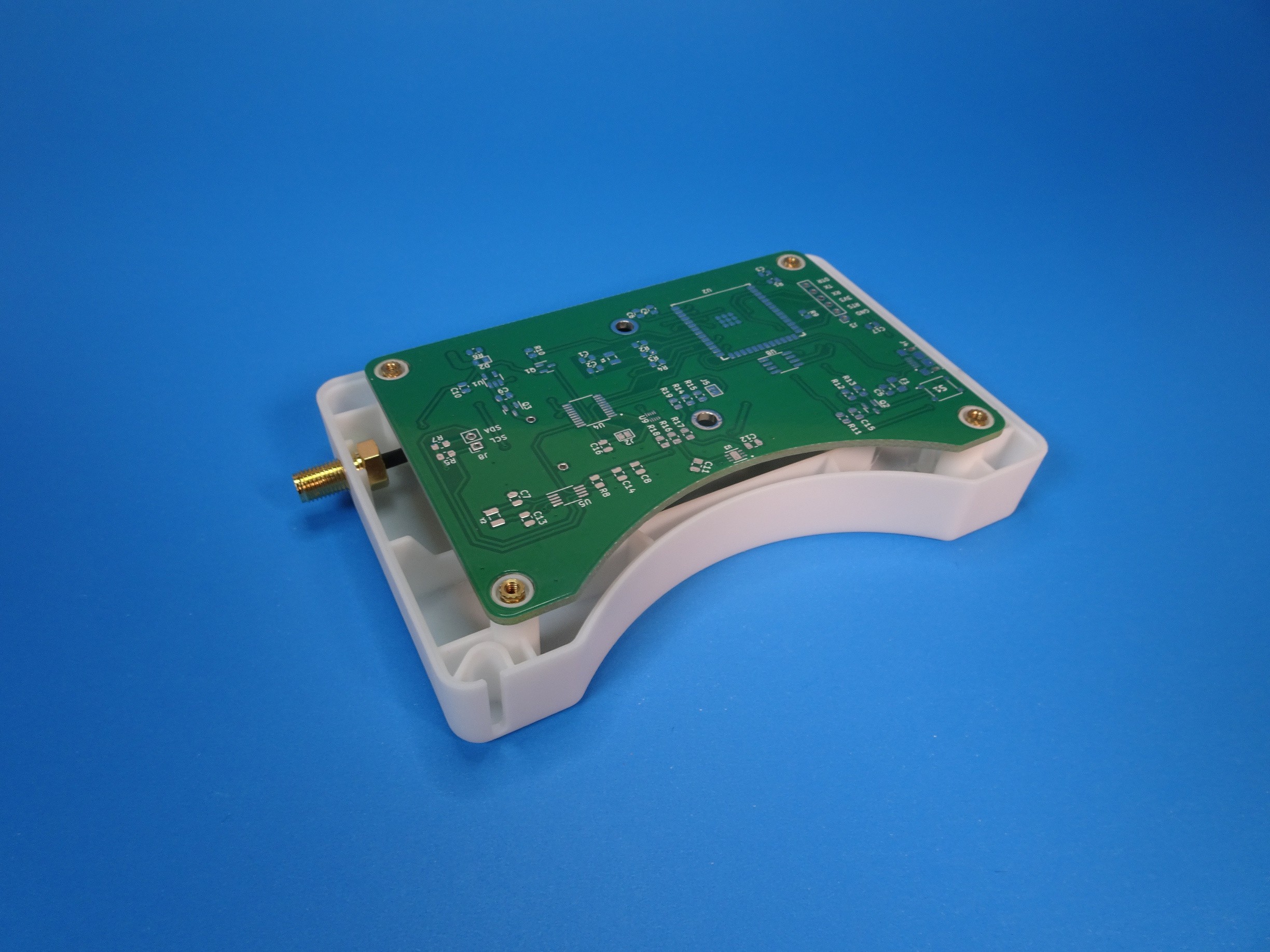
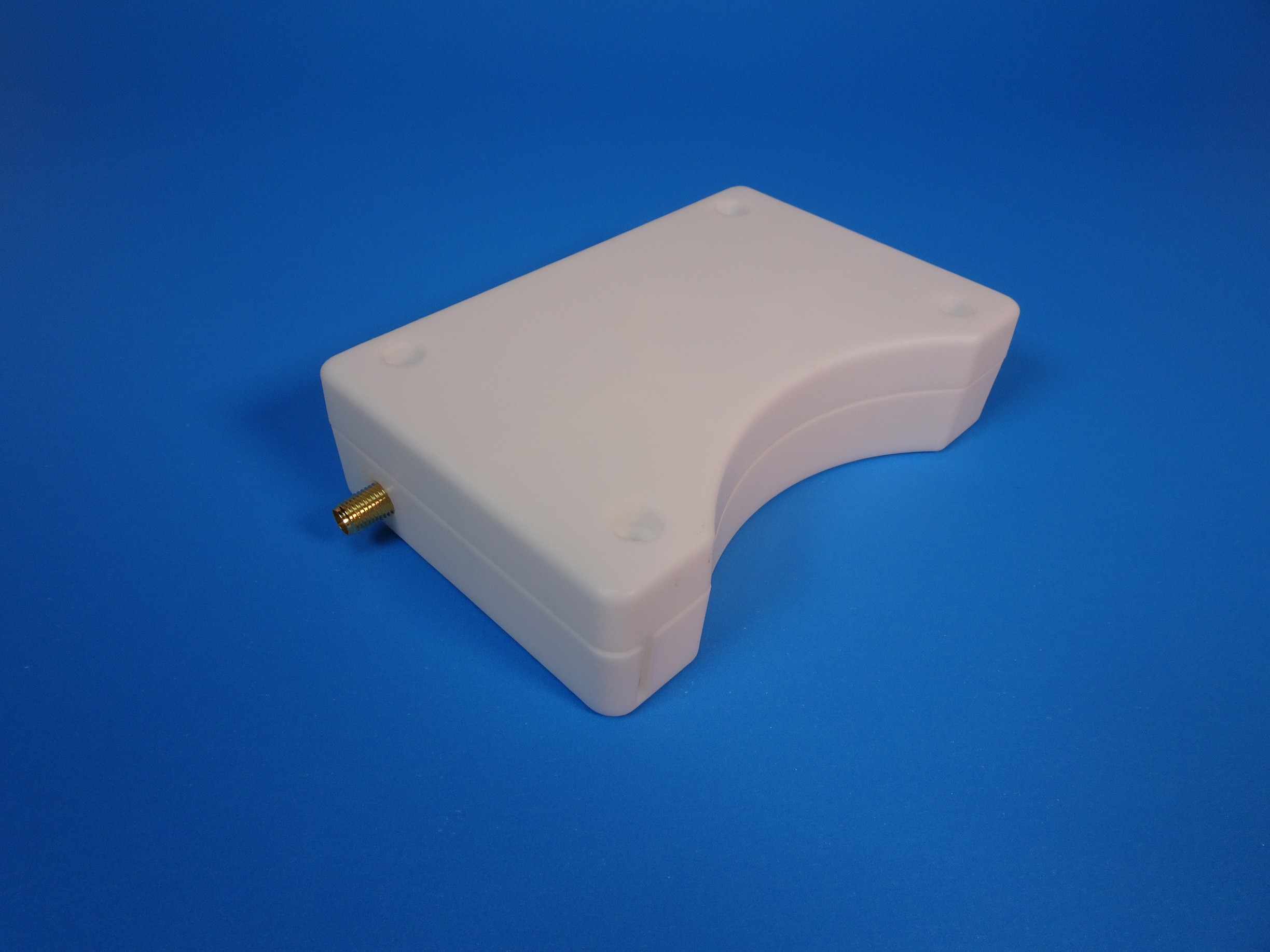
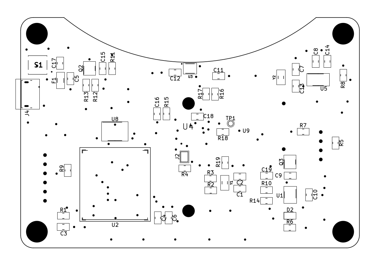
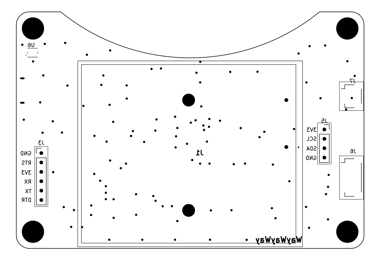
Hardware Design Decisions
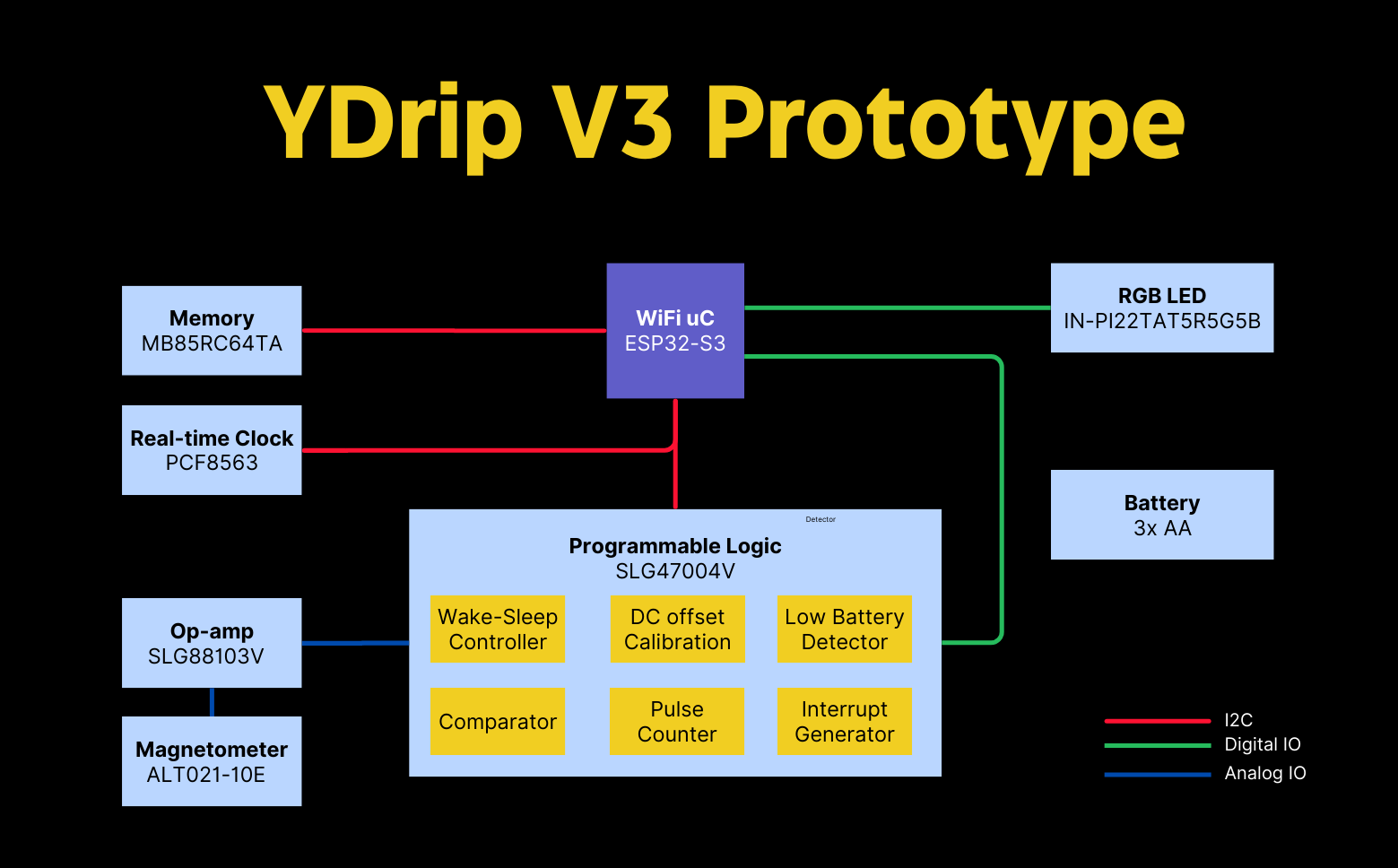
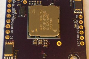
The main limitations on the hardware designs are affordability and battery life. Many IoT devices require a hub to bridge the low power RF like LoRa to WiFi/Ethernet. This increase cost and complexity for an initial prototype. However, using WiFi presents challenges with power consumption. An ultra low power reprogrammable digital logic chip was chosen to offset this. It allows for maximum flexibility while using less power than general purpose CPU for meter reading.
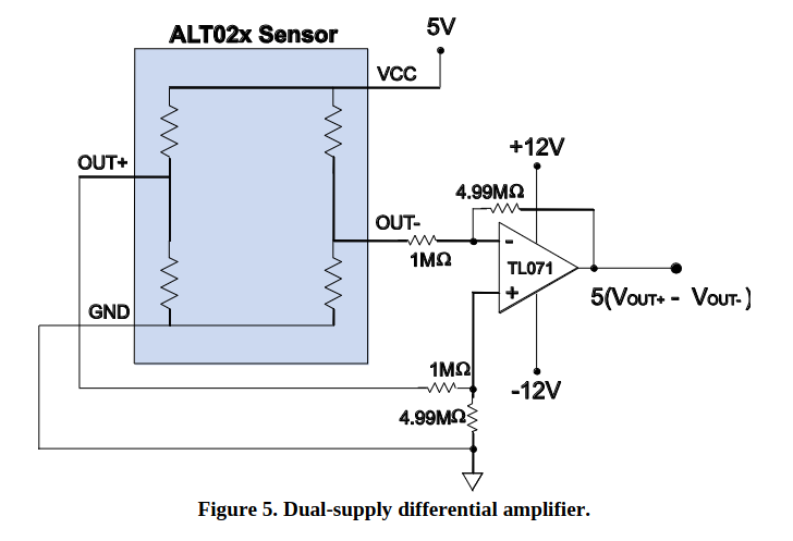
An ultra sensitive tunneling magnetoresistance (TMR) sensor was chosen for maximum measurement distance, which reduces the need for excessive signal amplification.
Software Design Decisions
The choice of ESPHome software...
Read more »

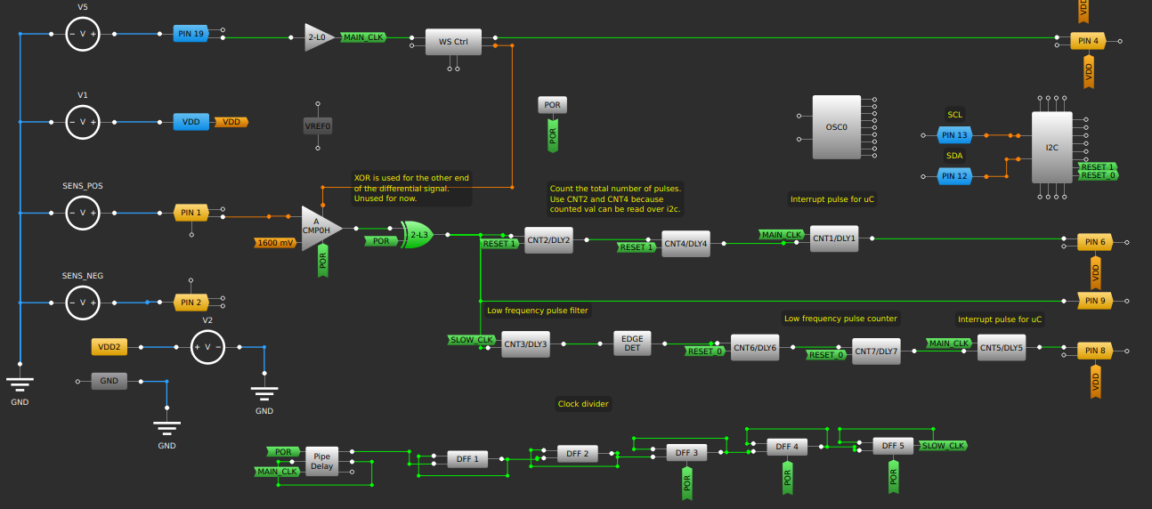
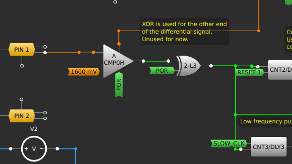
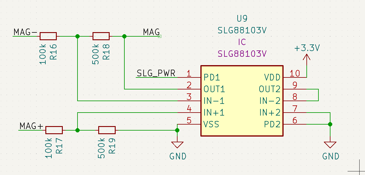
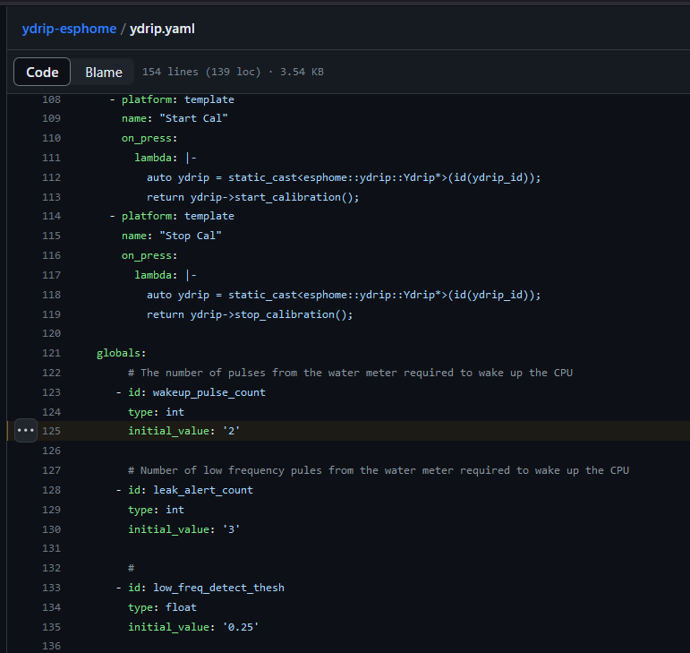
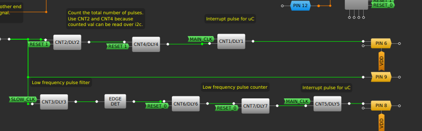 The high/low output of the comparator splits into two paths. The top path measures the total water usage. It consists of two programmable 8 bit counters. When they overflow that triggers a third counter configured as a one shot counter to send a short wake-up pulse to the ESP32S3.
 Green & Yellow = Sensor 1
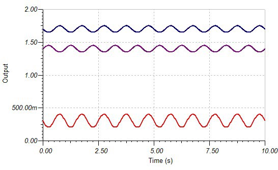
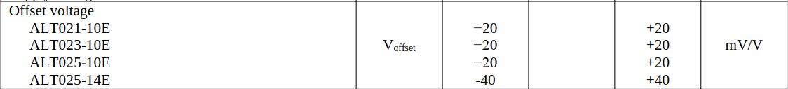
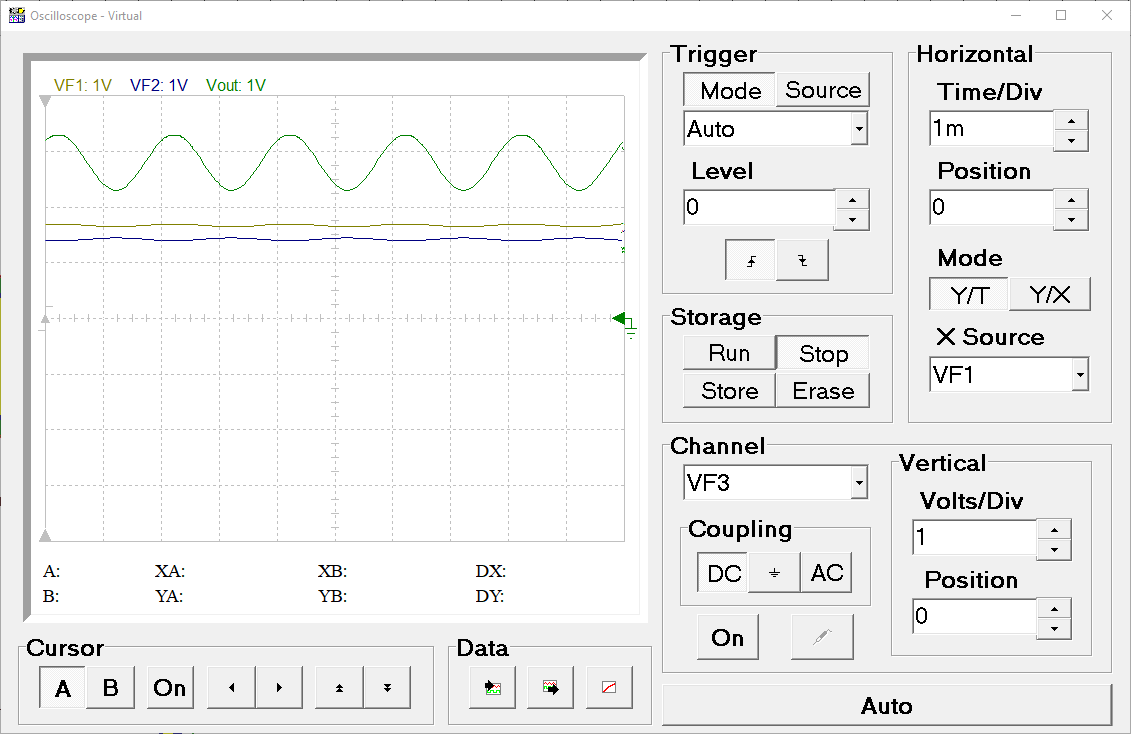 The bottom two lines are 50mV sine waves with 180 degree offset at 1.41V and 1.68V (sensor 1). We can see the output signal (green) is offset by about 2.6V. Let's take a look at sensor two which...
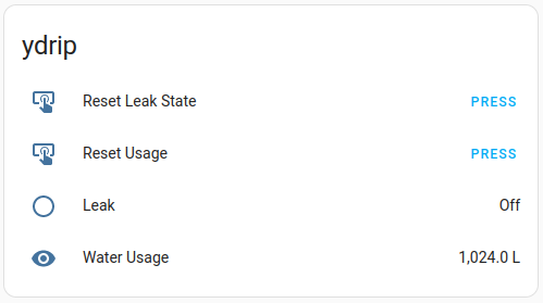


 Kris Winer
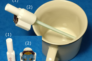
 jflaschberger
 Alexander Dvorkovyy
 YJ
YJ
Great project and neat implementation. I tried to build something like that a few years back -> https://hackaday.io/project/179532-retrofit-waterstop