 ydrip
ydripThis is the first version of the water meter reader I created after flushing hundreds of dollars down the drain due to a bad toilet. My city water meter apparently had a leak detection feature, but it didn't trigger and even if it did, I would see it since it only notifies you with a blinking LED. (My meter is in the basement). This was also around the time I started using Home Assistant and wanted a native device that didn't rely on 3rd party APIs to retrieve the data. The first step was understanding how a water meter works.
How A Water Meter Works
There are two main parts to a water meter: The first is the brass housing with a mechanical flow meter that rotates a magnet. I'll call this the water meter. The second is a mechanical or electrical reader that measures the number of rotations. I'll call this the water meter reader. The water meter reader that your city installs sits on top of the meter so it's closest to the magnet inside. Here is a good animation of how this all works at 45 seconds.
V0 Prototype
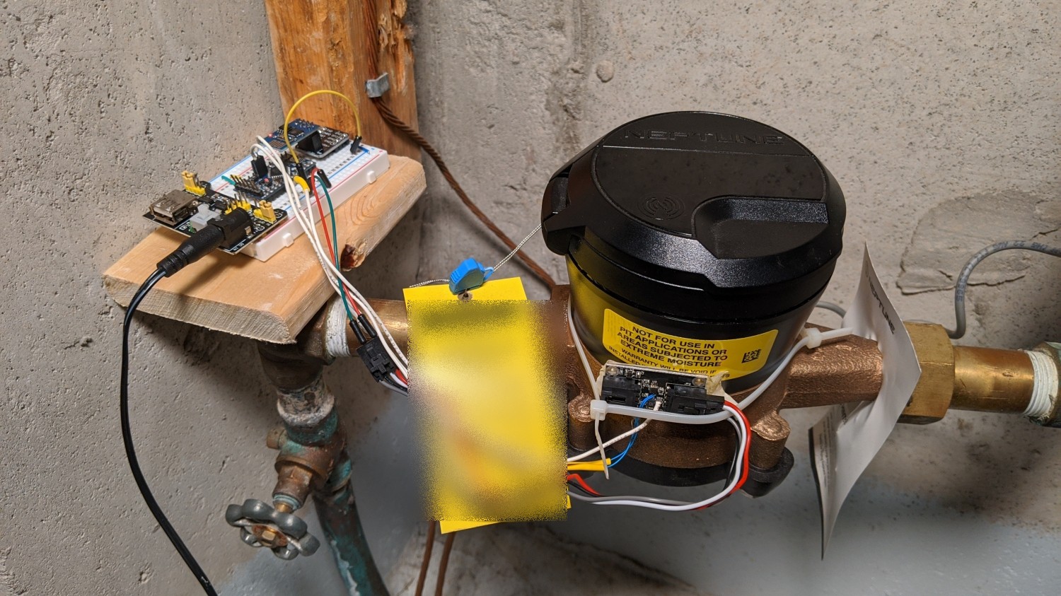
The first prototype used an ESP8266, an Arduino mini and a LIS3MDL magnetic sensor (zip tied under the yellow sticker in the image above). The magnetic sensors in the video above do all of the hard work by converting the analog output of the varying magnetic field, which looks like a sine wave, into neat pulses a microcontroller can read. Each pulse or sine wave cycle corresponds to a rotation of the magnet (this depends on the number of polls it has), which gives you the volume of water through the pipe. Unfortunately, most are designed to sit a few millimeters away from the magnet and that spot is taken by the city reader so I had to mount mine on the side. I tried over a dozen parts from Mouser/Digikey, but couldn't find anything sensitive enough so that left a few options.
- Get a raw analog magnetic sensor and build a circuit to amplify the output and add hysteresis.
- Use a sensitive digital magnetic compass with built in amplification and do hysteresis in software.
I went with #2 for simplicity of hardware.
The simplest way to count sine wave cycles is a zero crossing detector. Hysteresis is utilized to mitigate false triggering caused by signal noise near the zero-crossing threshold. TI does a better job of explaining it here with pictures. The same principles apply in hardware or software.
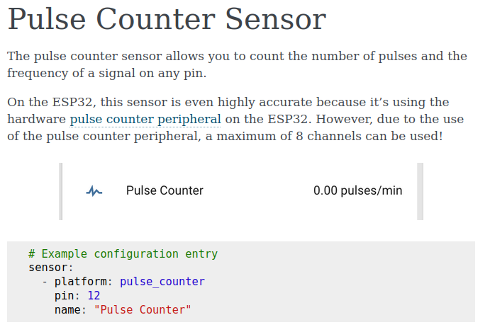
The Arduino would toggle a GPIO for each magnet rotation to the ESP which would transmit it to Home Assistant. I used ESPHome to create the firmware for the ESP. It's a 'no code' required platform that lets you define common functions in a YAML script. In this case I used their Pulse Sensor feature.
Everything was working well enough that I thought I would share it with the community as a kit, but I needed to make a few improvements.
- Simplify instillation: Mounting the magnetic sensor improperly could result in a different sine wave DC offset. I could solve this in software and/or improve the mounting mechanism.
- Make a PCB to avoid the rats nets of wires.
Discussions
Become a Hackaday.io Member
Create an account to leave a comment. Already have an account? Log In.