 ydrip
ydripSponsor
This version of YDrip was kindly sponsored by PCBWay. They have been my PCB vendor for version 1 and 2 so I'm thrilled they decided to sponsor the manufacturing for v2.5. I've used them in the past because their website provides real-time updates with the status of your product and their support engineers provide great design feedback to make sure their are no manufacturing delays. The ordering process is also extremely easy with their KiCad plugin, which automatically packages your board design, opens a browser, and adds it to your shopping cart.
This was my first time ordering 3D printed STL parts from PCBWay and I'm very satisfied with the result. The 0.8mm lip that connects the two halves of the enclosure printed perfectly along with all of the ribs for rigidity. Their part finishing is also well done with no signs of support marks or warping. The PCB quality is what you've come to expect with no flaws and good enough dimensional accuracy to friction fit into the case. Thanks PCBWay.
Electronic Design Changes
The ALT021-10E is an ultra sensitive magnetic sensor (0-0.25 mT). It's so sensitive that I've been able to use it without an amplification stage which has reduced BOM costs and complexity. Unfortunately, I've run into a few problems.
- The earth's magnetic field can interfere with measurements depending on the device position.
- Some water meters have very weak magnets that are not measurable with the current design.
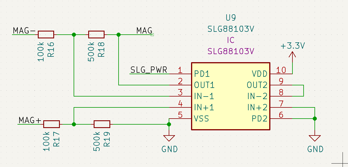
To fix these issues, I decided to add an op-amp to amplify and offset the output signal. I chose the SLG88103104 from Renesas which has a stunning 375 nA quiescent current per channel. It also has a shutdown pin which I can duty cycle with the sensor, but it almost wouldn't make a difference in the total power budget.
The opamp is setup as a differential amplifier with both sides of the wheatstone bridge sensor going to the +- inputs of the amplifier. (Ignore the resistor values. They are just place holders)
A better design would use an instrumentation amplifier to avoid loading the wheatstone bridge which could reduce accuracy if not take into account. One way to mitigate this is by using much larger input resistors than the bridge resistance (10k in this case). Here is an example from the datasheet. This app note from TI goes into more details about the tradeoffs for each approach.
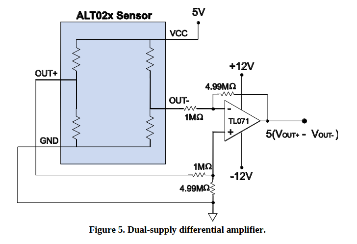
This is great, because instrumentation amps cost more and drain more power. The addition of the amp solved my initial problems, but I ran into new ones.
New Problems...
Up until now I've been reusing some parts like the mag sensor since they were out of stock at the time. This meant I didn't have to deal with device to device variances which would impact my amplifier design. Silly mistake.
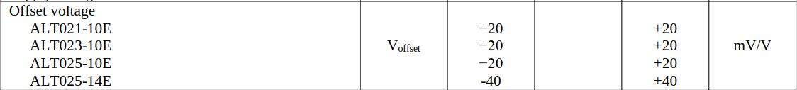
The ALT021 wheatstone bridge DC offset variance is +- 20mV. We can see that in the datasheet and following plots.
Pink & Blue = Sensor 2
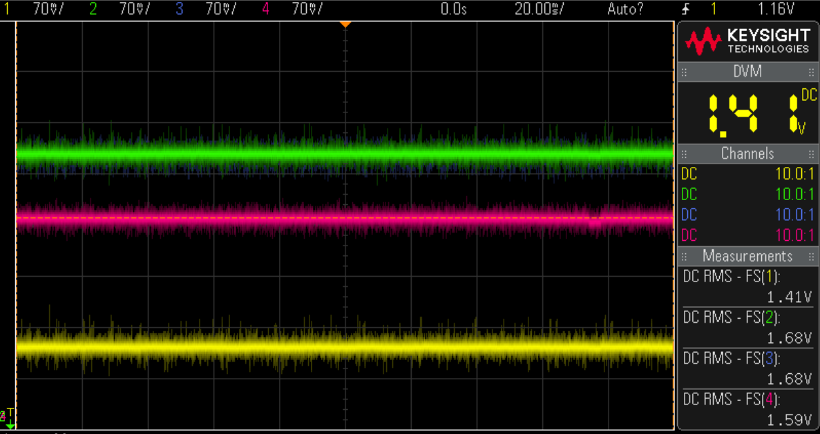
Sensor 1 has a difference of 27mV between differential pairs and sensor two has a difference of 9mv. Here are the same devices rotated by 90 degrees.
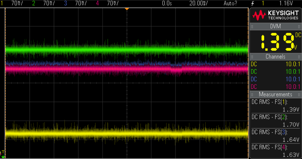
There is a 2mv - 4mv change due to the earth's magnetic field.
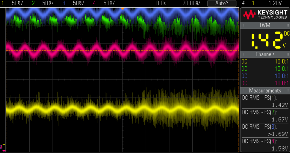
This last plot is with a magnet spinning near the sensors.
In a perfect world both signals would be centred around Vcc/2 or 3.3V/2 = 1.65V with no magnetic field. The problem starts when you try to amplify the difference between the two differential pairs. The difference in DC offset between sensor 1 and sensor 2 will also get amplified resulting in an output signal with an even larger offset. Here is a simulation with sensor 1.
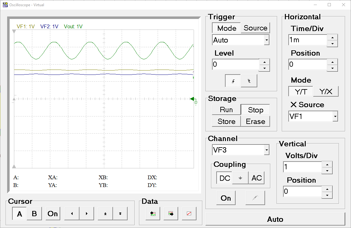 The bottom two lines are 50mV sine waves with 180 degree offset at 1.41V and 1.68V (sensor 1). We can see the output signal (green) is offset by about 2.6V. Let's take a look at sensor two which had a smaller offset between pairs.
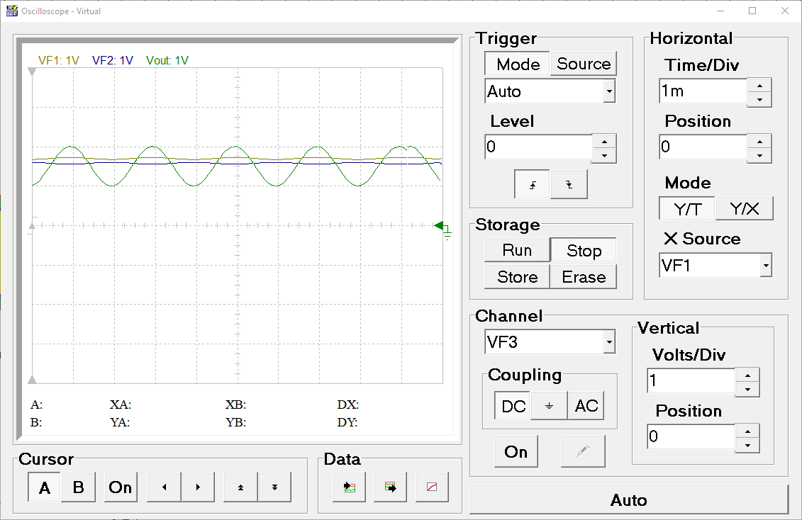 The output signal is now centred at 1.5v.
 In summary, there are two factors that impact the DC offset of the amplified signal. The DC offset variance of the wheatstone bridge and the earths magnetic field. This is important to characterize because the analog comparator needs a reference voltage to compare when counting 'zero' crossings. Should it be set to 2.6V for sensor one or 1.5V for sensor two? What happens if the device moves and that offset changes?
Possible Solutions
These are some of the possible solutions I considered:
- Apply a high pass filter to remove the DC offset. The issue with this approach is it will filter very slow moving signals i.e. small leaks which could take hours to spin the magnet. Passive components would need to be large to not filter this signal.
- Use software to remove the offset. This would be difficult to do reducing battery life significantly since this is moving the processing to a CPU instead of digital logic as it is now.
- Calibrate each sensor in the factory and correct any offset with shunt resistors. While possible, this is too expensive and time consuming.
- Use a DAC to bias the opamp and correct the offset dynamically. This could work since the calibration only needs to be done once by a uC.
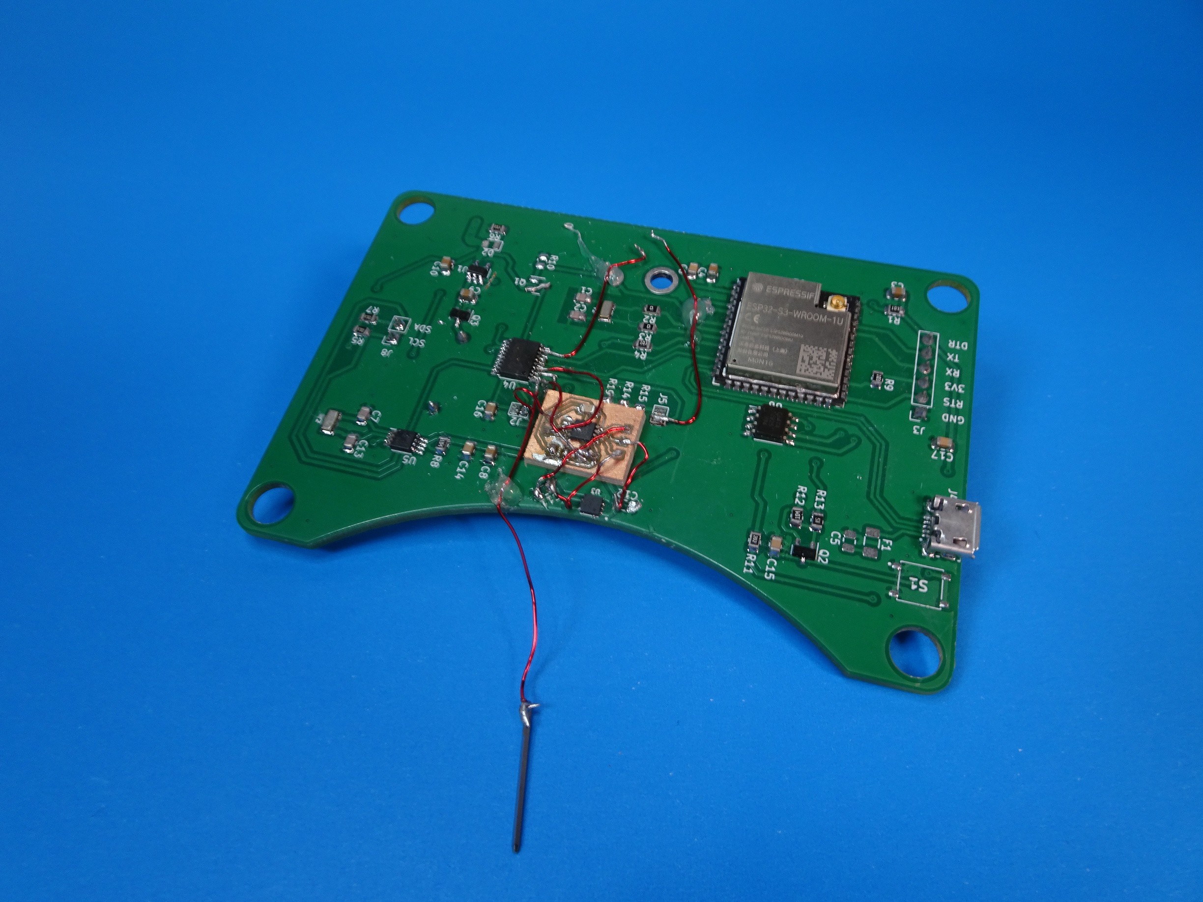
I'm currently prototyping a dynamic calibration method similar to 4 which will be the subject of a future post. Here is the picture proof.
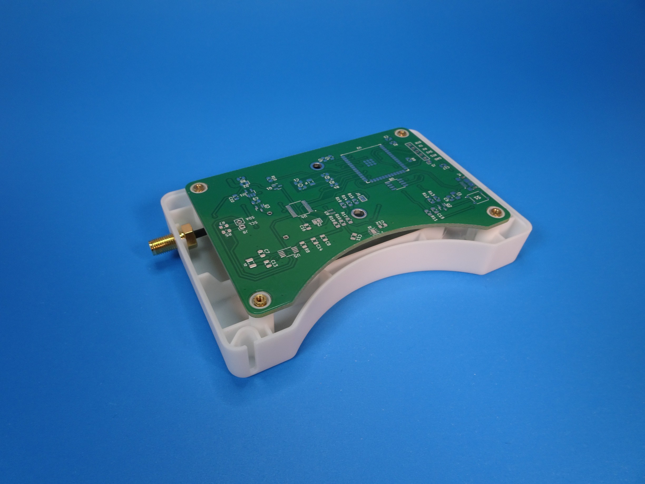
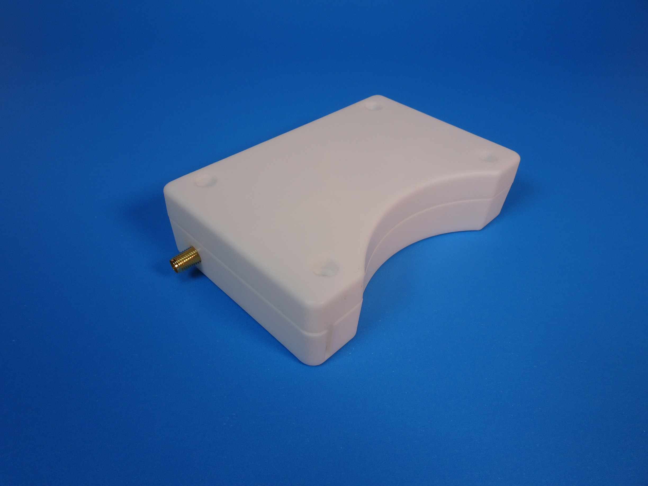
Enclosure Design Changes
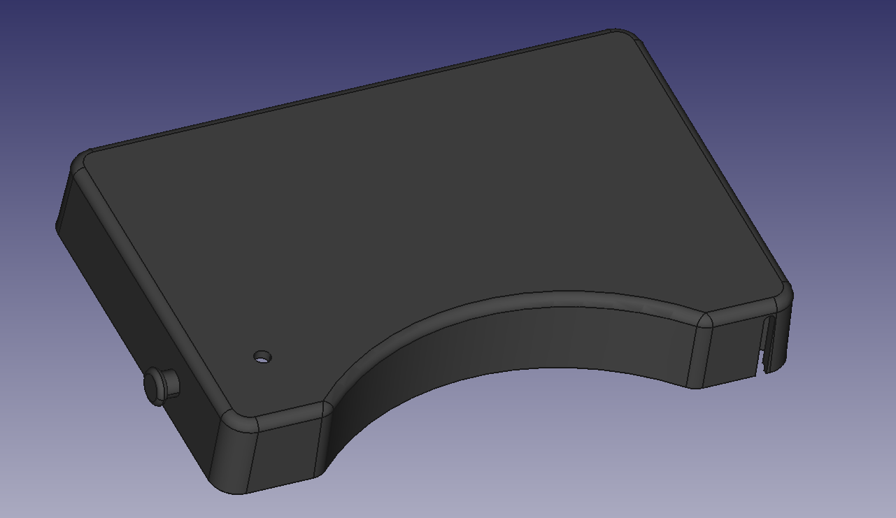
The only major change for this version was to flip the mount orientation of the device. This allows the sensor to sit closer to the magnet, which improved signal detection. However, this meant the LED lens had to be moved. There wasn't enough room to add a cut out with the YDrip logo like the previous design so I opted for a simple circular LED lens.
Discussions
Become a Hackaday.io Member
Create an account to leave a comment. Already have an account? Log In.