 ydrip
ydripV3 (beta) of YDrip has been assembled and tested. The main goal of this version was to add dynamic gain and DC offset control. This makes the design able to measure gas meters and water meters with weak magnets from a larger distance.
Analog Front End
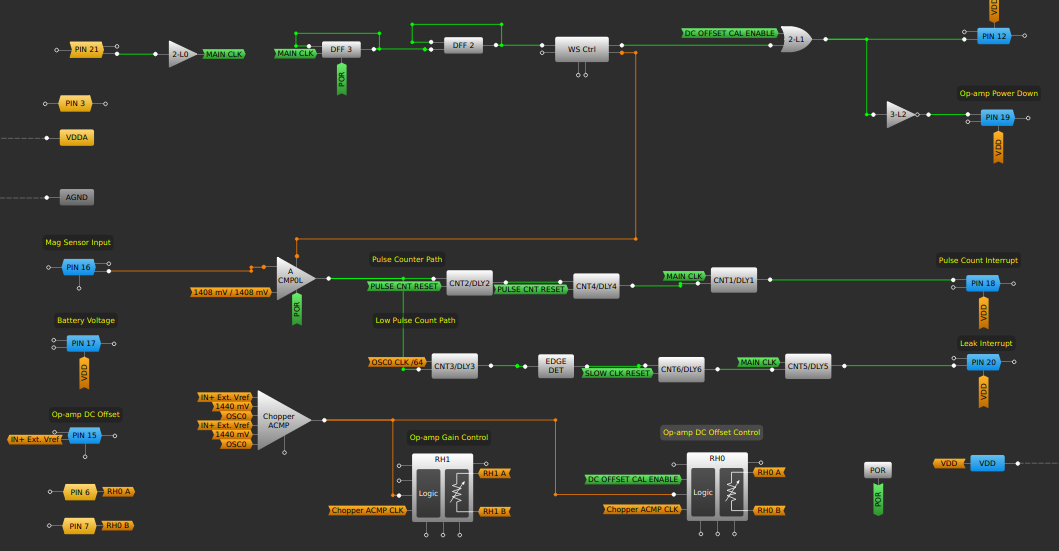
I have upgraded to the SLG47004V from the SLG46826 because it has more analog capabilities. Specifically, it includes opamps, rheostats and more analog comparators. The opamps don't have power down capabilities so I've decided to stick with the external SLG88103V for longer battery life. The digital logic design is basically the same except for the two rheostats at the bottom of the picture above.
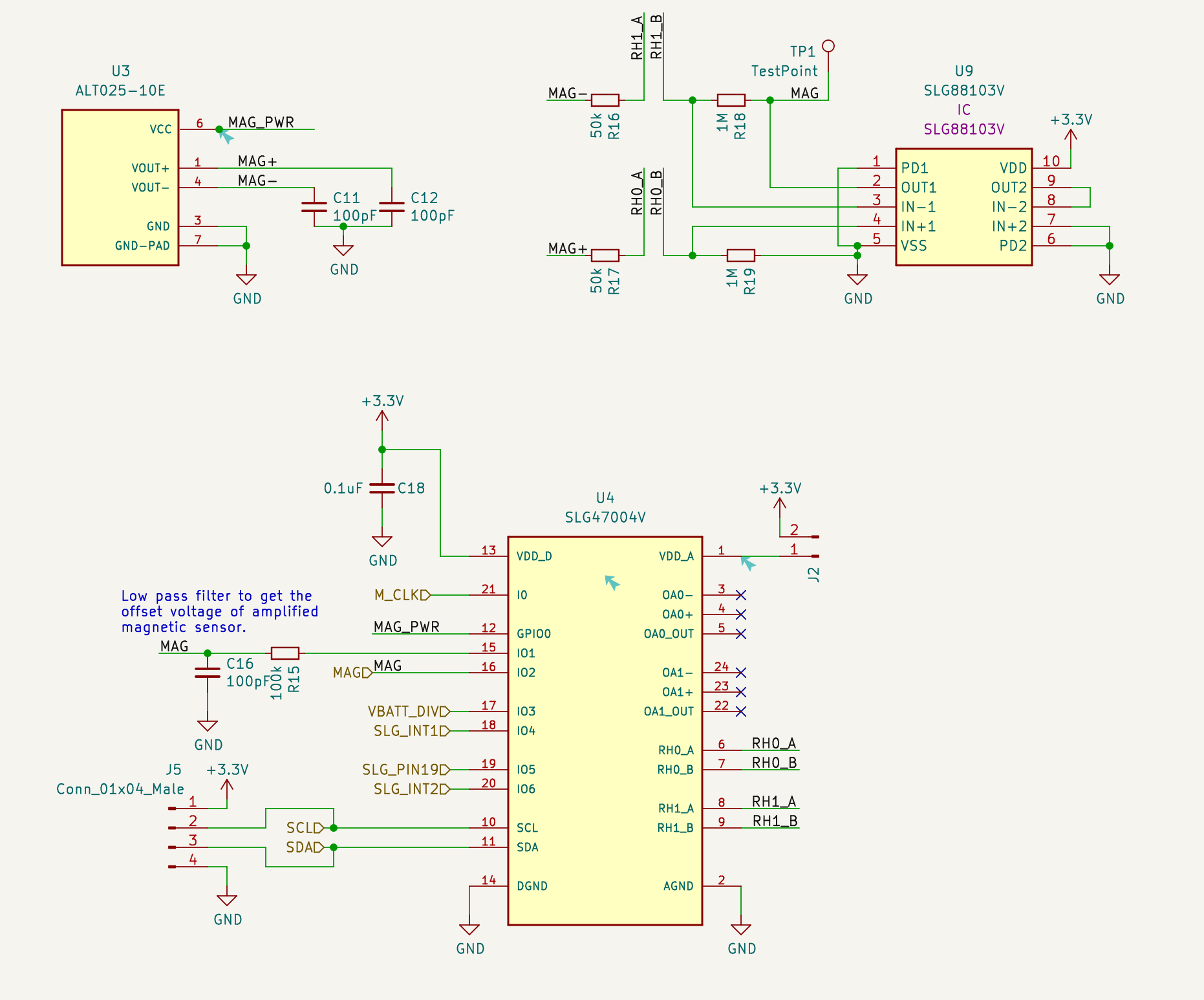
The rheostats (pins RHx_[A/B]) act as the feedback resistors for the SLG88103V opamp. The SLG47004V has the capability to dynamically control the rheostats using the chopper analog comparator, which is only being used to control the DC offset at the moment.
Here is how it works. The DC offset of the amplified mag sensor output is measured using a low pass filter (pin 15 of the SLG47004V). The chopper analog comparator compares this voltage with a chosen reference. 1.4v in this case. The comparator then sends up/down signals to the rheostat until there is no difference between the two voltages. The rheostat is connected to the biasing resistors of the opamp.
Here is a video showing the difference with and without automatic DC offset control. The output amplified signal is no longer affected by the earth's magnetic field making is much easier to calculate zero crossings.
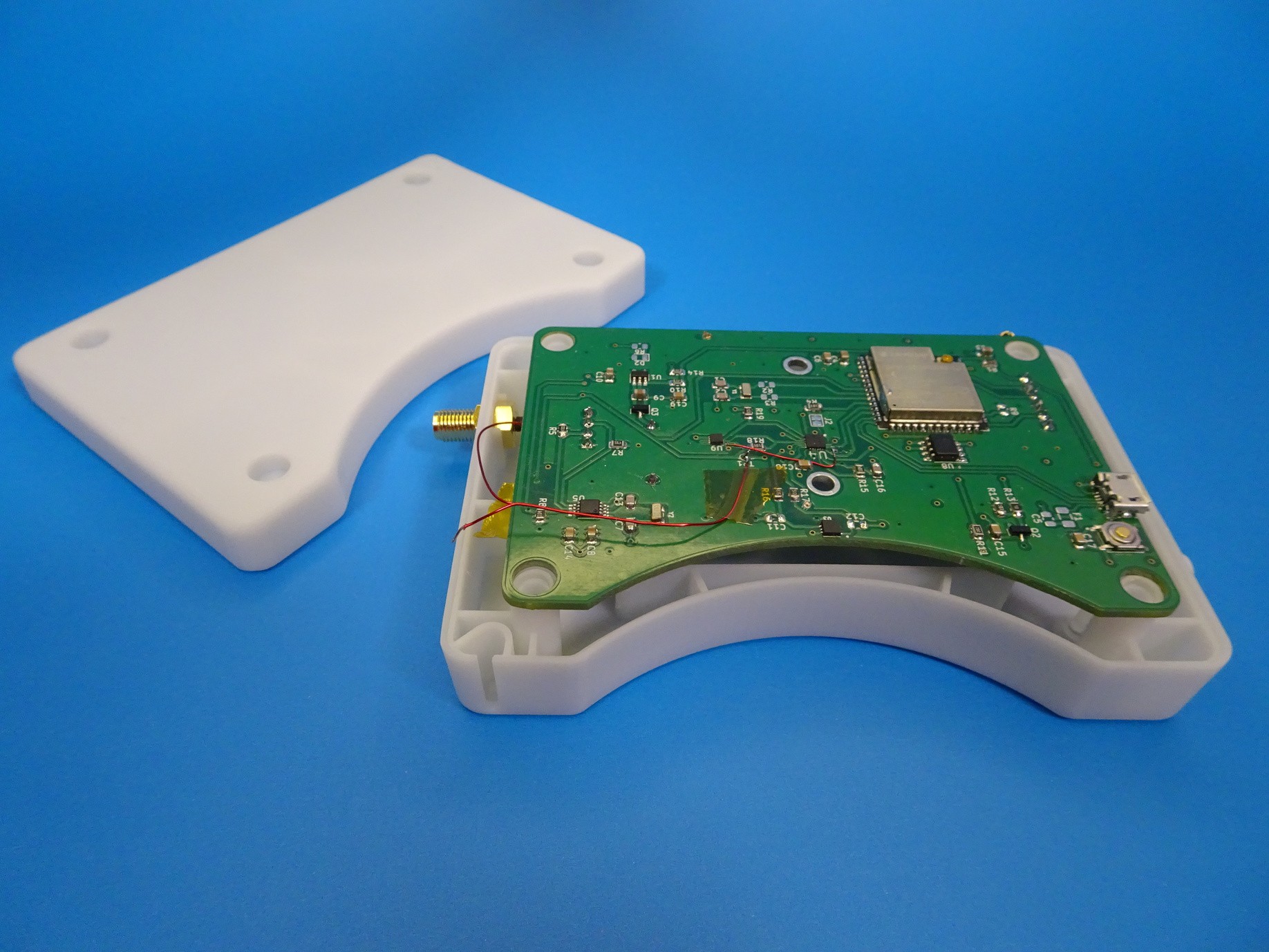
Enclosure
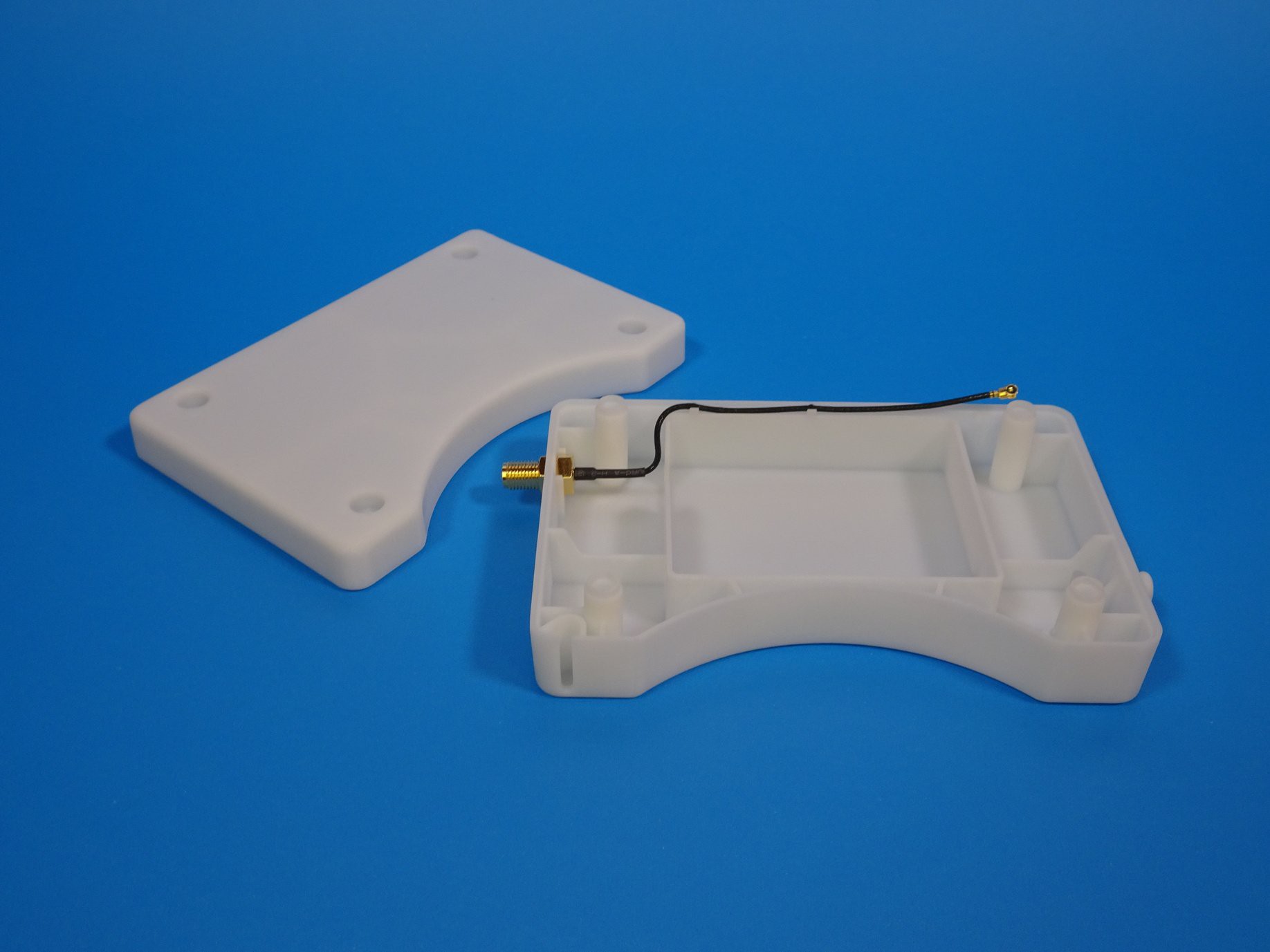
The enclosure design remains mostly the same with the exception of a change in the intended installation orientation. It is now meant to be installed upside down so the PCB is closer to the magnet in the water meter. This meant I needed to redesign the light guide since there was no room for the old one on the other side of the PCB due to the battery holder.
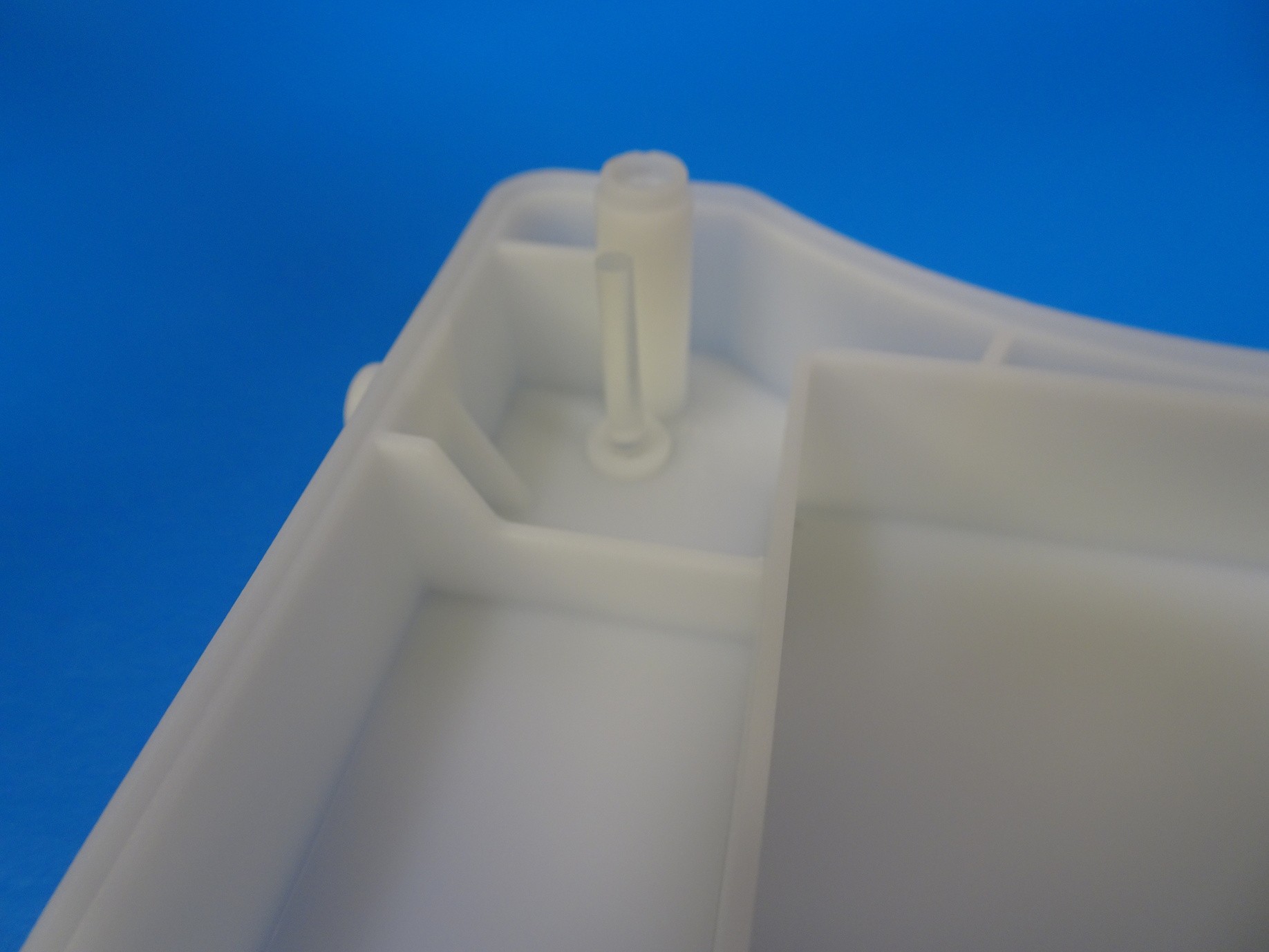
I went with a cylindrical design and placed the LED in the corner.
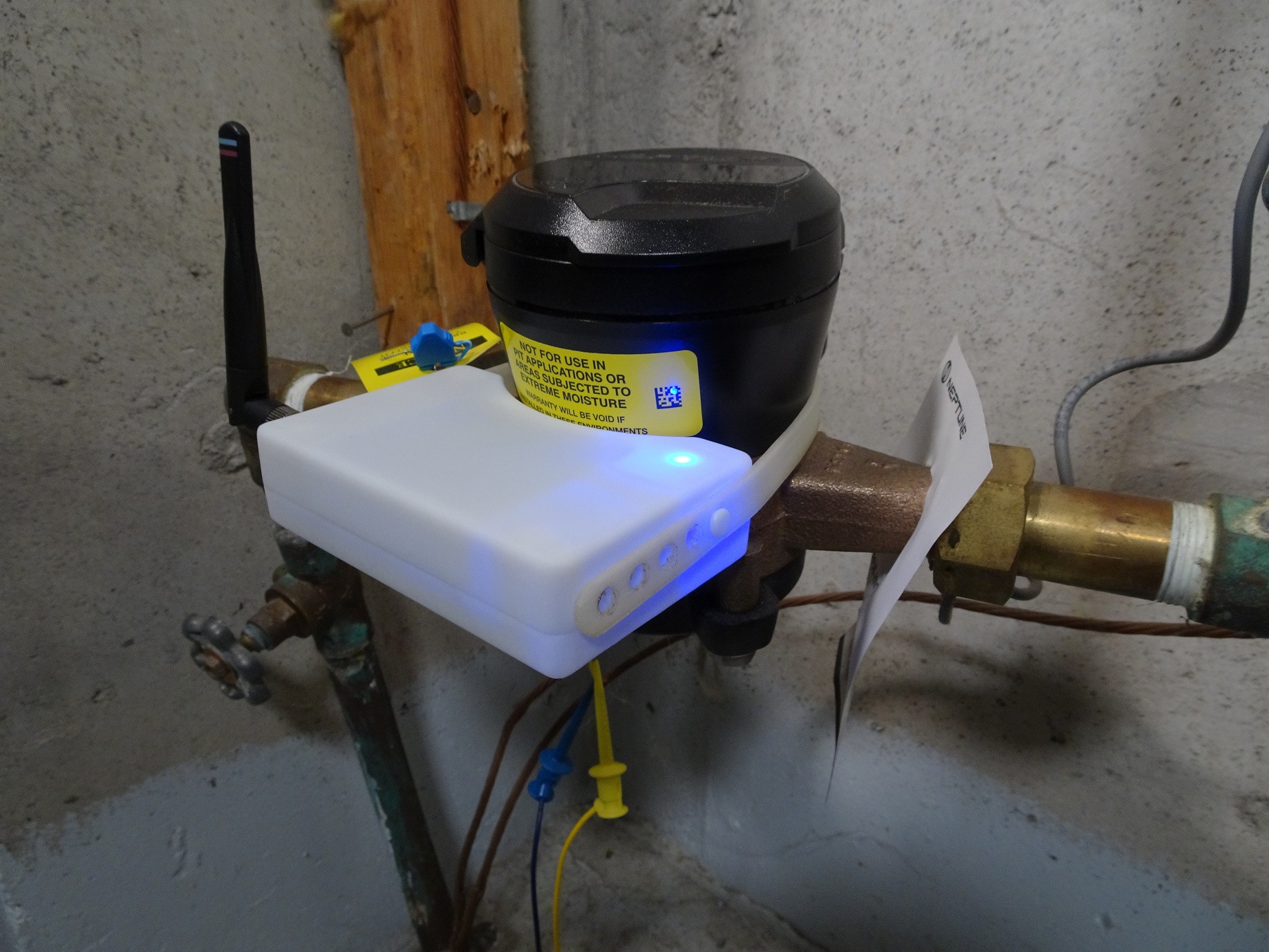
Here is what it looks like installed and running.
Other minor changes included: reduced the case rib size and a holder for SMA connector to make it easier to screw in.
Discussions
Become a Hackaday.io Member
Create an account to leave a comment. Already have an account? Log In.