This is a the point where I continue the 'Soldering SMD'. Last time I had to go back and fix the double rail power supply problem. Now it fixed and we may continue. First lets check the attenuator
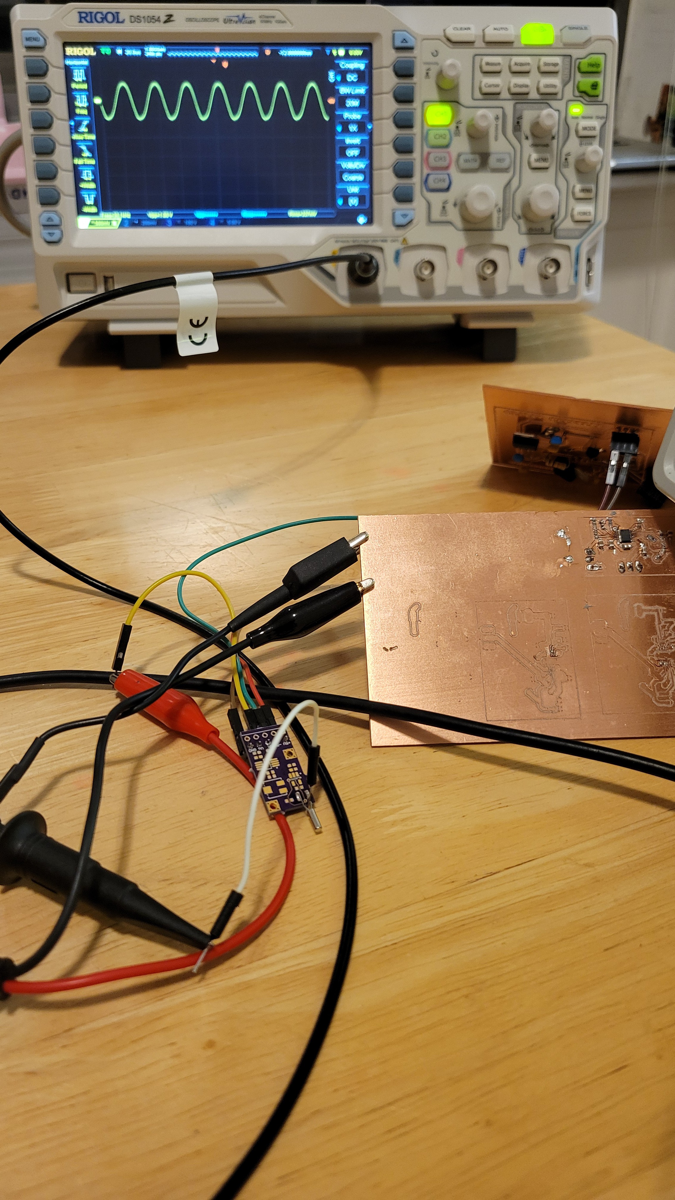
Looks good we got about 1Vpp.
I found something strange or bug in the design the guarding ring is not coated so terminals of quartz fork may touch it.
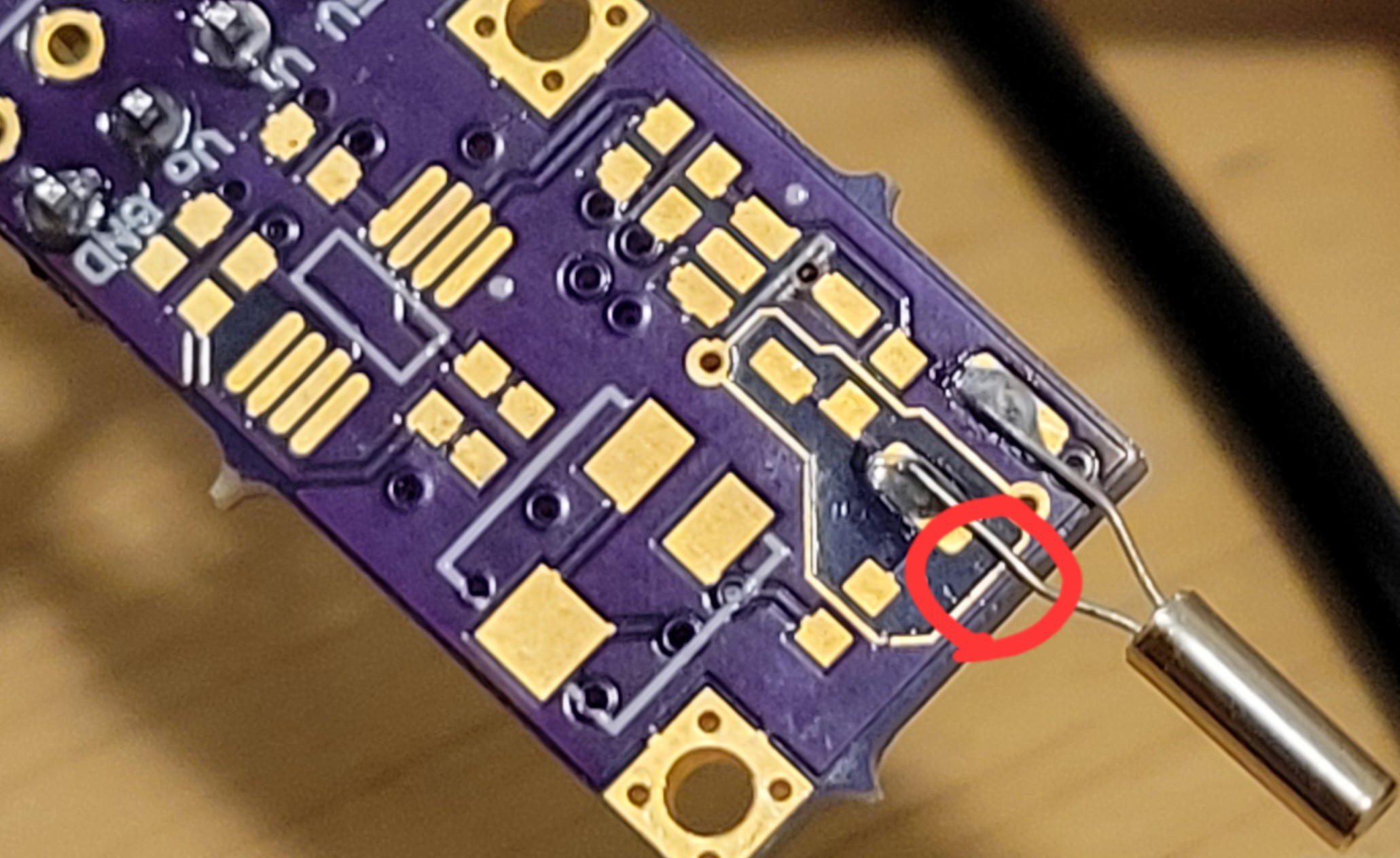
Thus may lead to short circuiting. Hmmm...
Now lets add all other components like OPA656 and another opamp.
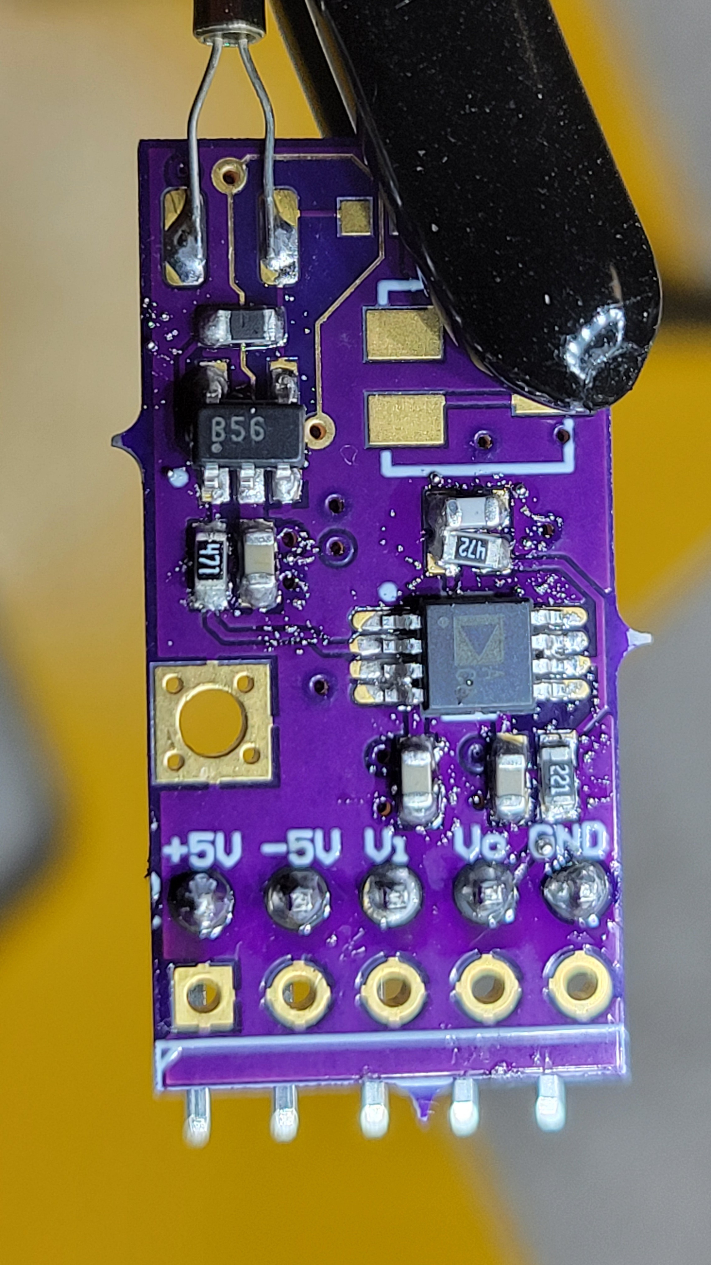
Had some problem of putting to much soldering paste and all pins was glued together. But some playing around solved the problem.
Let's plug it in.... I will continue tomorrow it's getting too late...
The test was not successful, once I connected everything I got only noise. Since I don't have too much testing point I tested the output of attenuator. I was surprised to get there no signal. After while, I checked the power lines no power! What ?! Once disconnected power was back. The problem is I got shirt circuit somewhere. Found some problems in my soldering but still got no output. Checked attenuator output, still none. It *was* working before, how we went back?
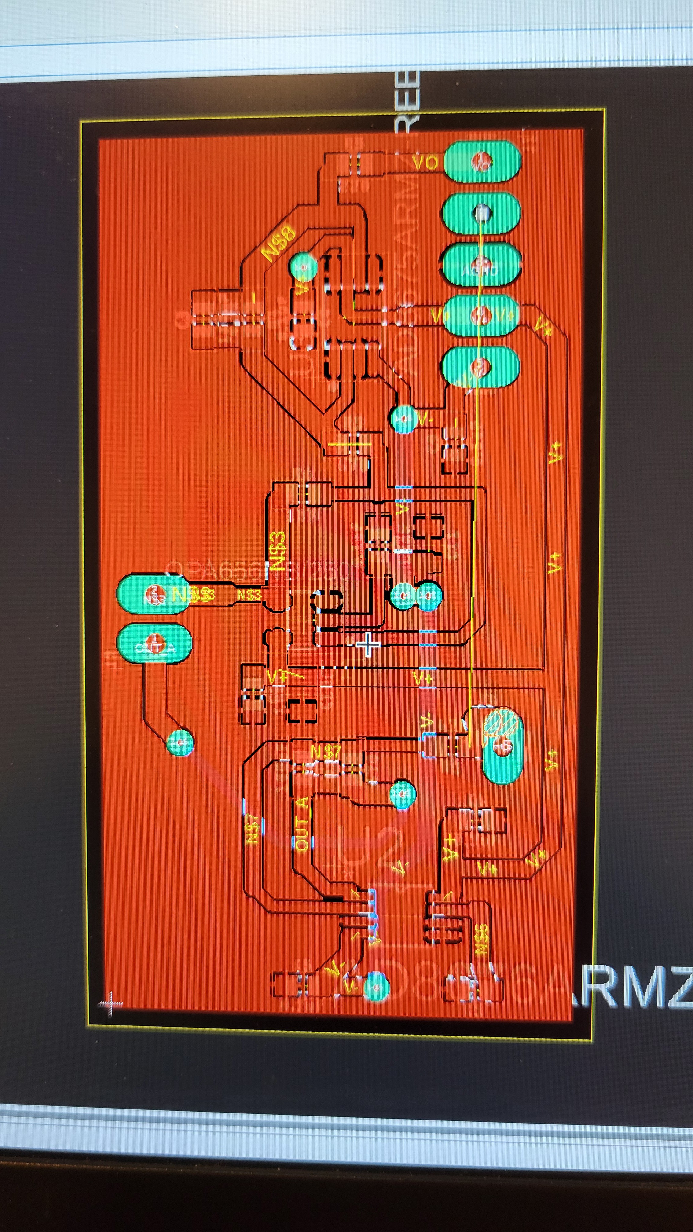
Now I don't know what to do. Should I try to debug while I don't have accurate board design. (The one I got once I bought the board is blurry) or should I design one myself?
After couple of days I've tried to debug this PCB. I've decided to build my own version hopefully once I will start building I will understand what is the problem with the previous one.
It uses the same schematic as the previous just without the capacitor compensation thing.
GCode seems ok.
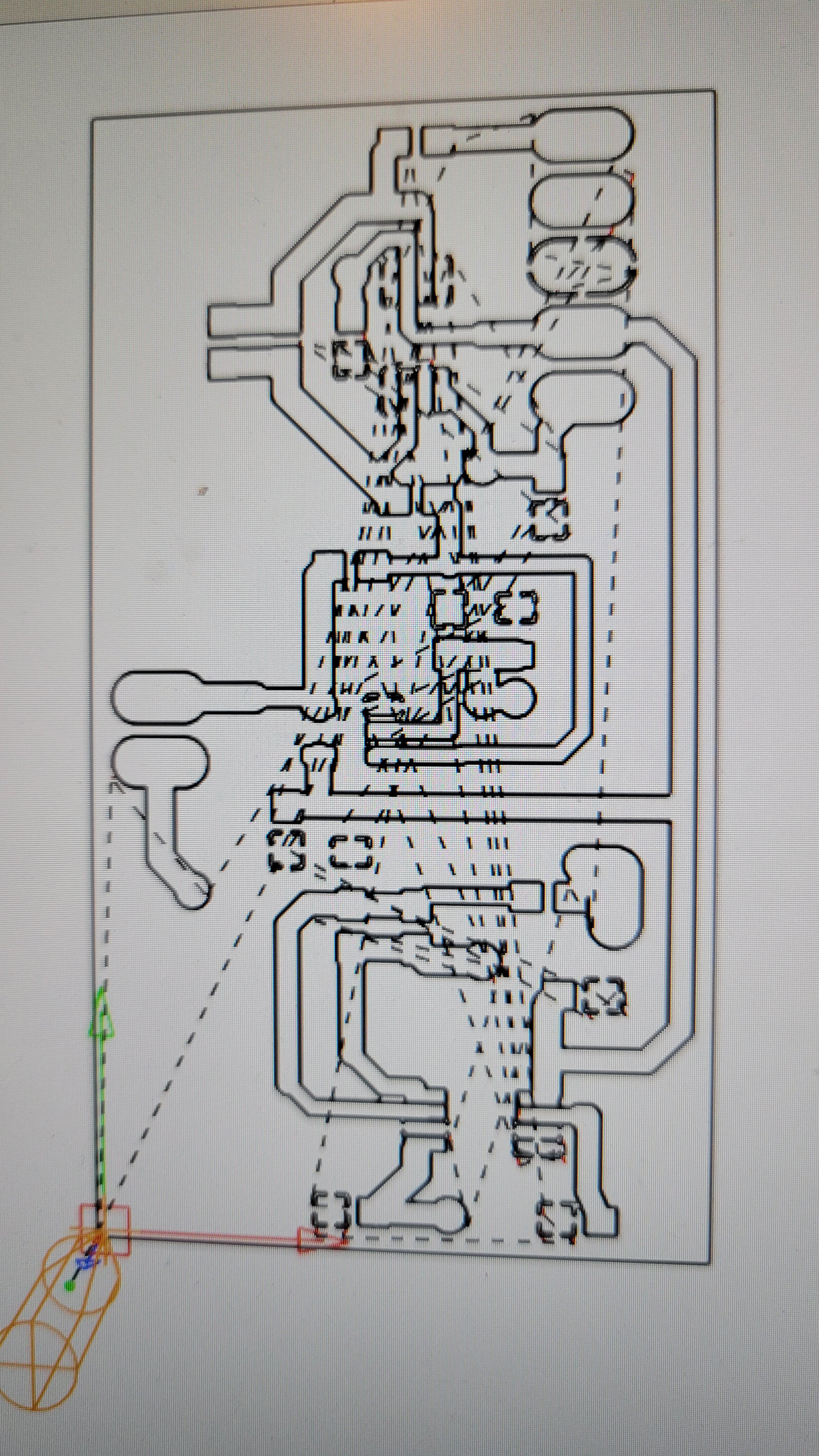
I've tried to make it not to dense, otherwise it hell to connect all the timy components.
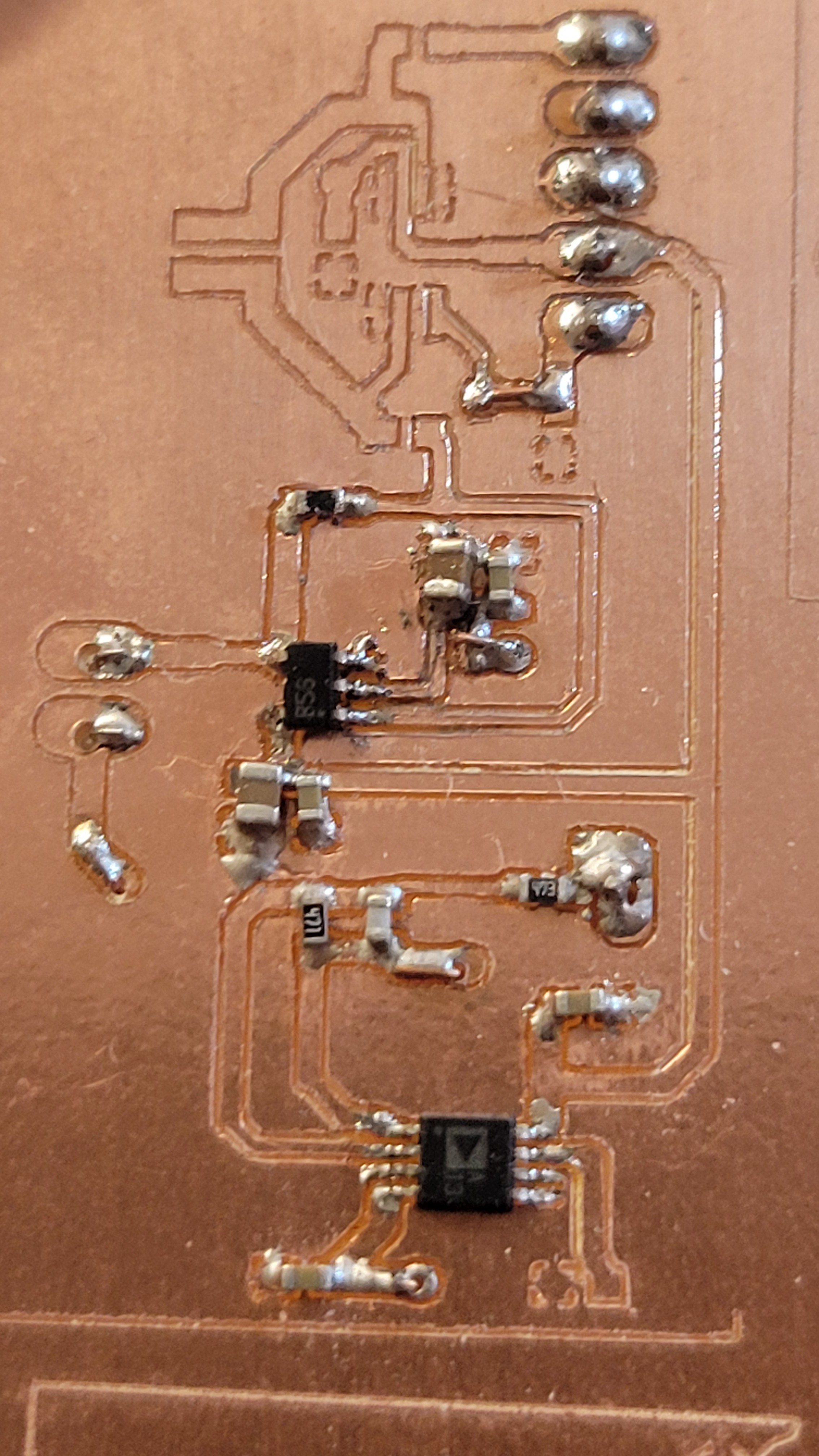
Printed the circuit using 15° 0.1mm v-bit.
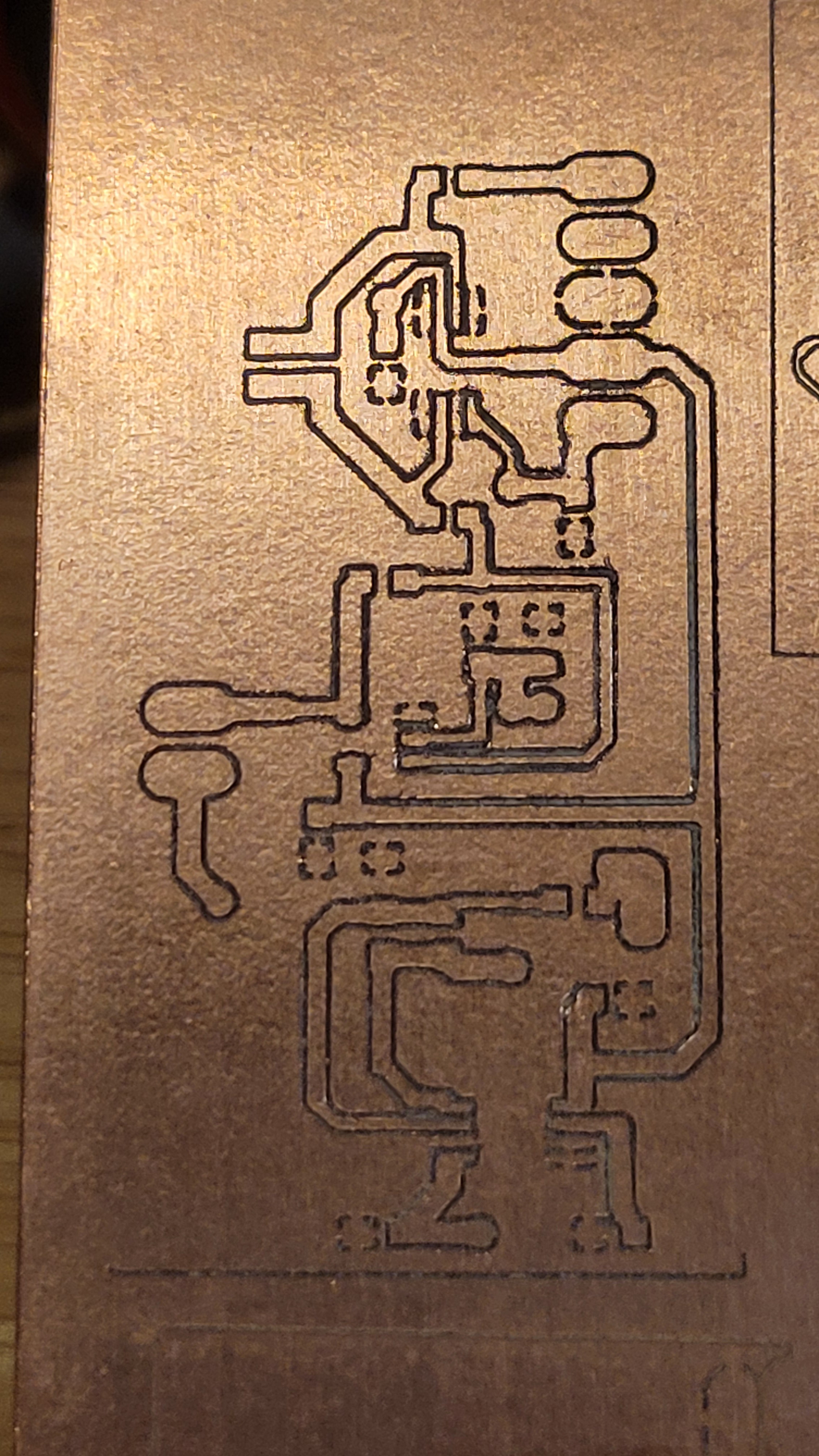
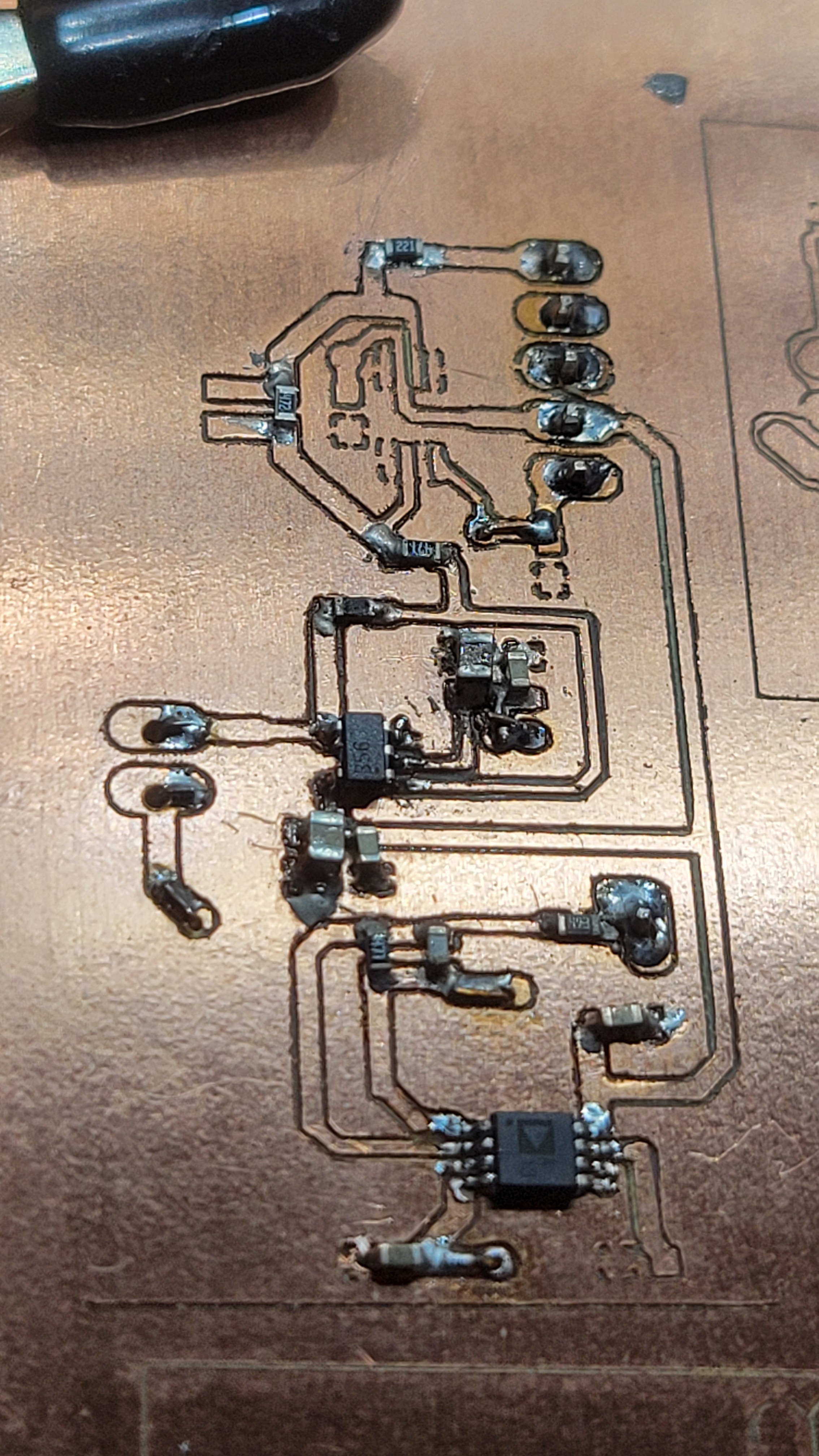
The quality is really good and still there always some parasite connections that created because of the copper debris. After some cleaning and connectivity check it looks OK.
Next step is solder chip by chip and check that each step is working properly.
Careful placement of components
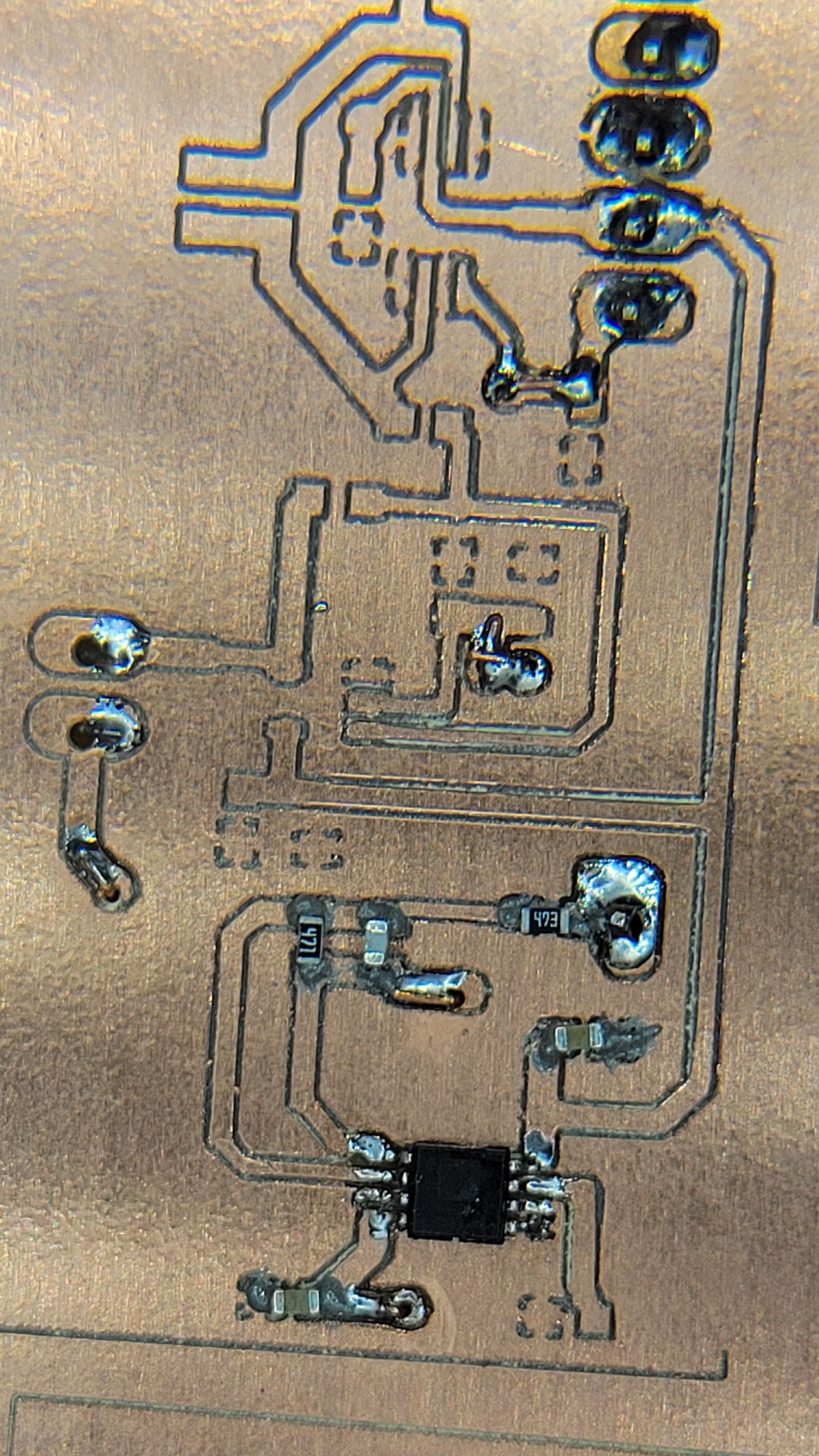
Gives lean result
I guess it's 'you reap what you sow'
Let's see if it's working as expected, it should get input from signal generator and attenuate it by 100.
After all the connections it's still not working. Changed to other AD8676 I had. Still same problem. Without power the resistors seems to propagate the signal. But once power applied everything goes down.
I've checked the power voltage it's only 4.6 and the minimal is 5v I was afraid to use 5v because of OPA656 it needs max 6 volts and I wanted to be on the safe side.
Let's try to increase voltage to 5.2v by using 430KOhm instead of 300KOhm.
----------------------------------------------------------------
Changed from 300KOhm to 430KOhm. The voltage is +5.6 and -4.6. That should be enough for our little omamp to come back to life. But what I get is only noise.
I am clueless....
I ran some simulations, with this configuration and 4v sinus input I we should get 40mV. Maybe the power rail high noise obscure it?
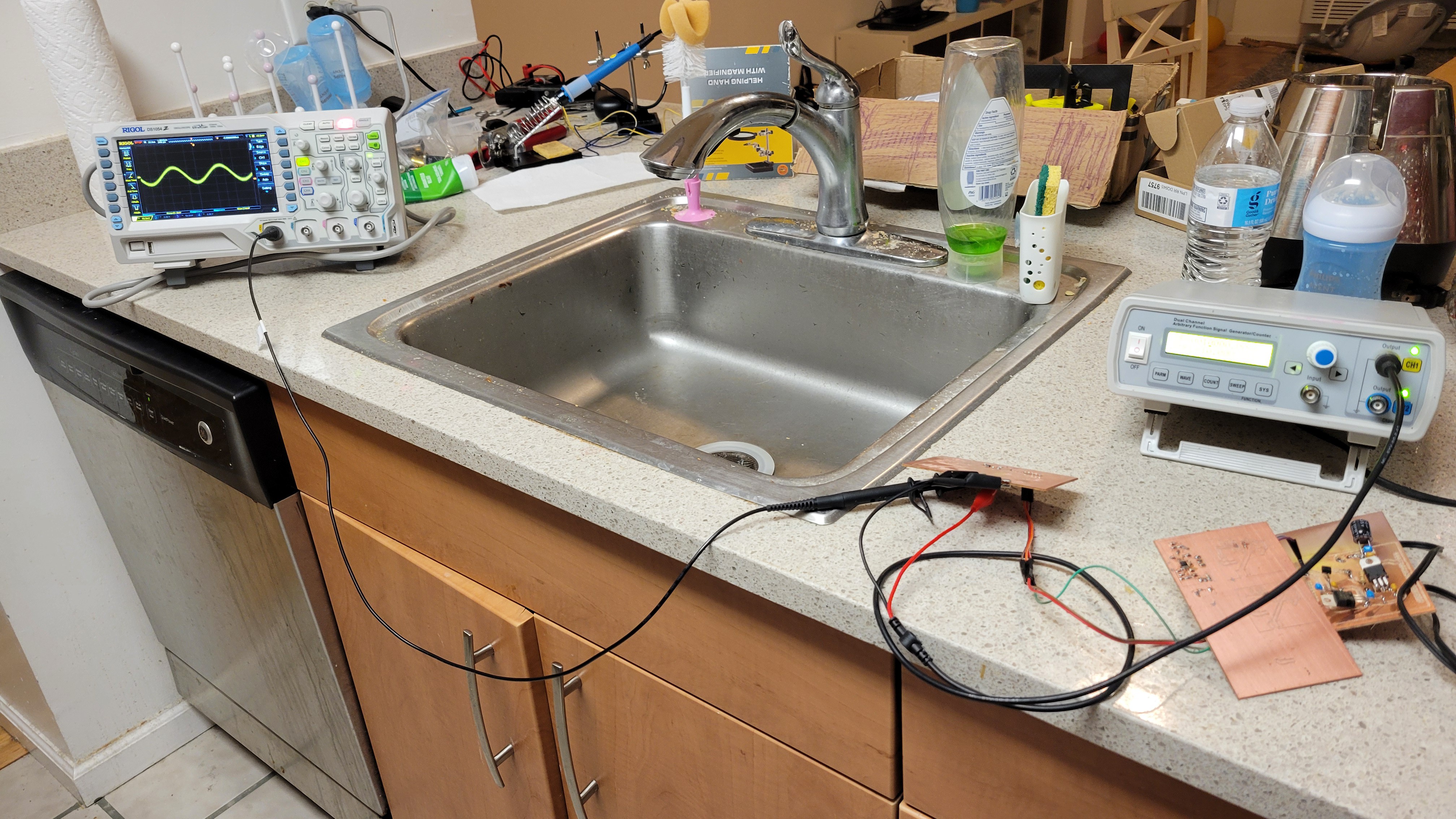
I'll have to test with old fashioned power supply wich doesn't have this switching noise.
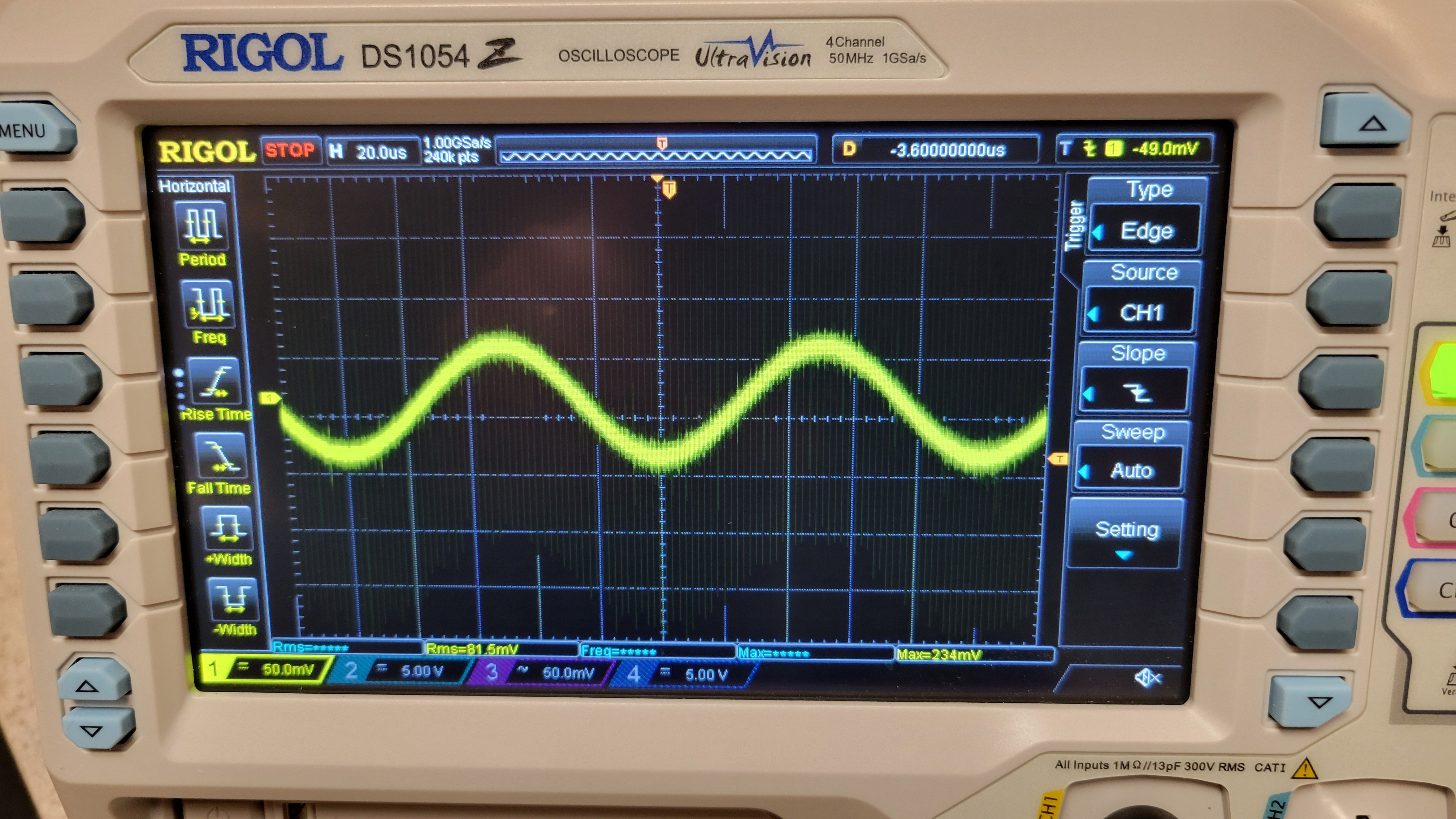
Yeah, that was it. Changed to old style power supply and got nice 50mV sinusoidal wave.
It's starting to get complicated as usual
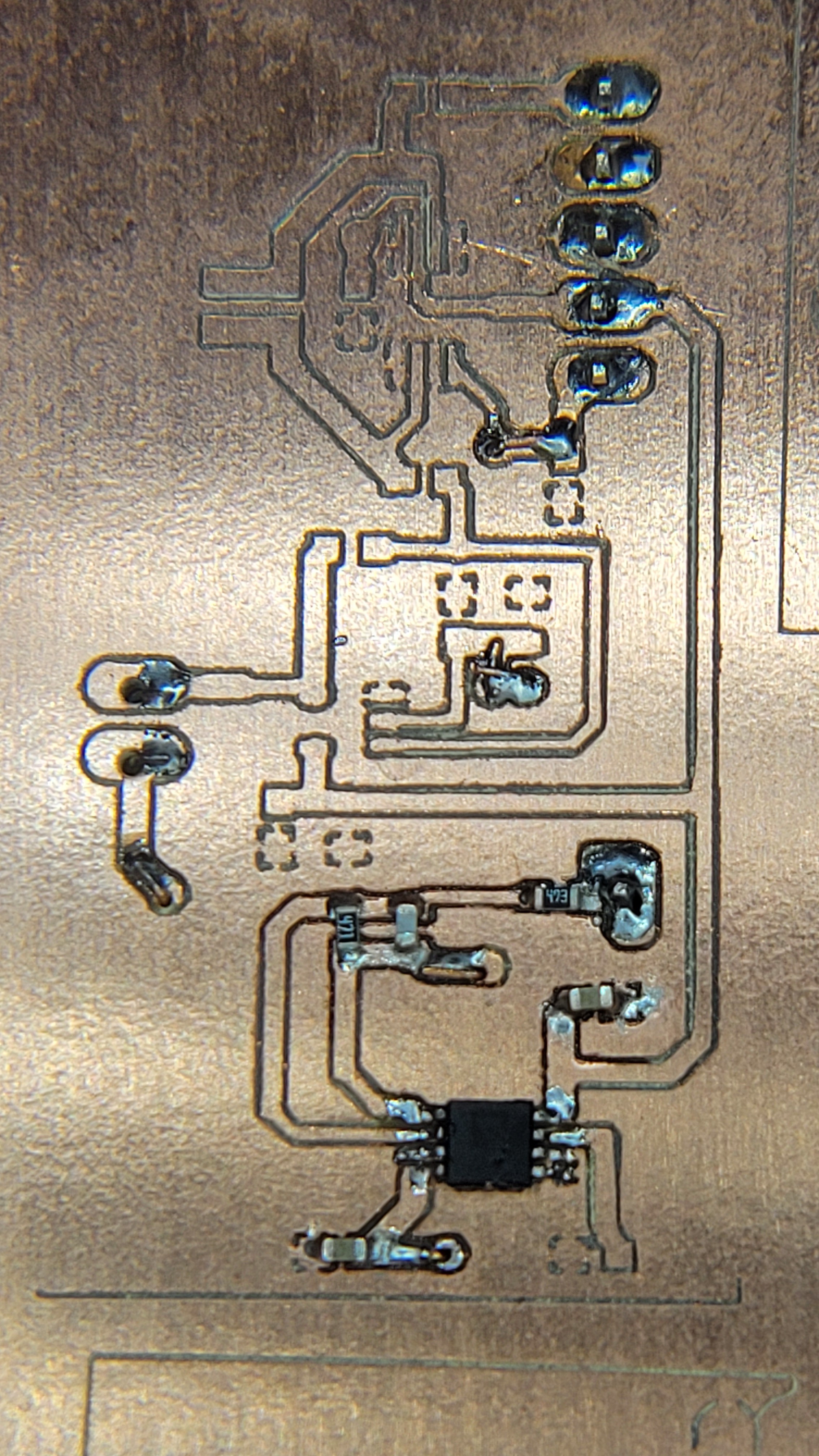
It took me few long hours to connect OPA656n
Fingers crossed, if this will work we can see that electrical part of AFM as done.
Added output resistors, this way connecting oscilloscope would be easier.
Powered on and .... NOTHING
It just doesn't work... Started testing each board independently and power seems to work fine provided nice 5.4v and charge pump board creating positive and negative voltages until I connect the latest one. Once connected negative rail goes to zero. It turns out that the new board is short circuiting negative rail to ground.
I am pretty sure I've checked it. Funny that this happened on the factory printed board too. This time I know how to debug and fix it.
Problem fixed... Let's hope this time it will work
SUCCESS!! Finally, I was able to connect all the boards and input frequency of 32765Hz. I was shocked to see that one Hertz changed amplitude so much.
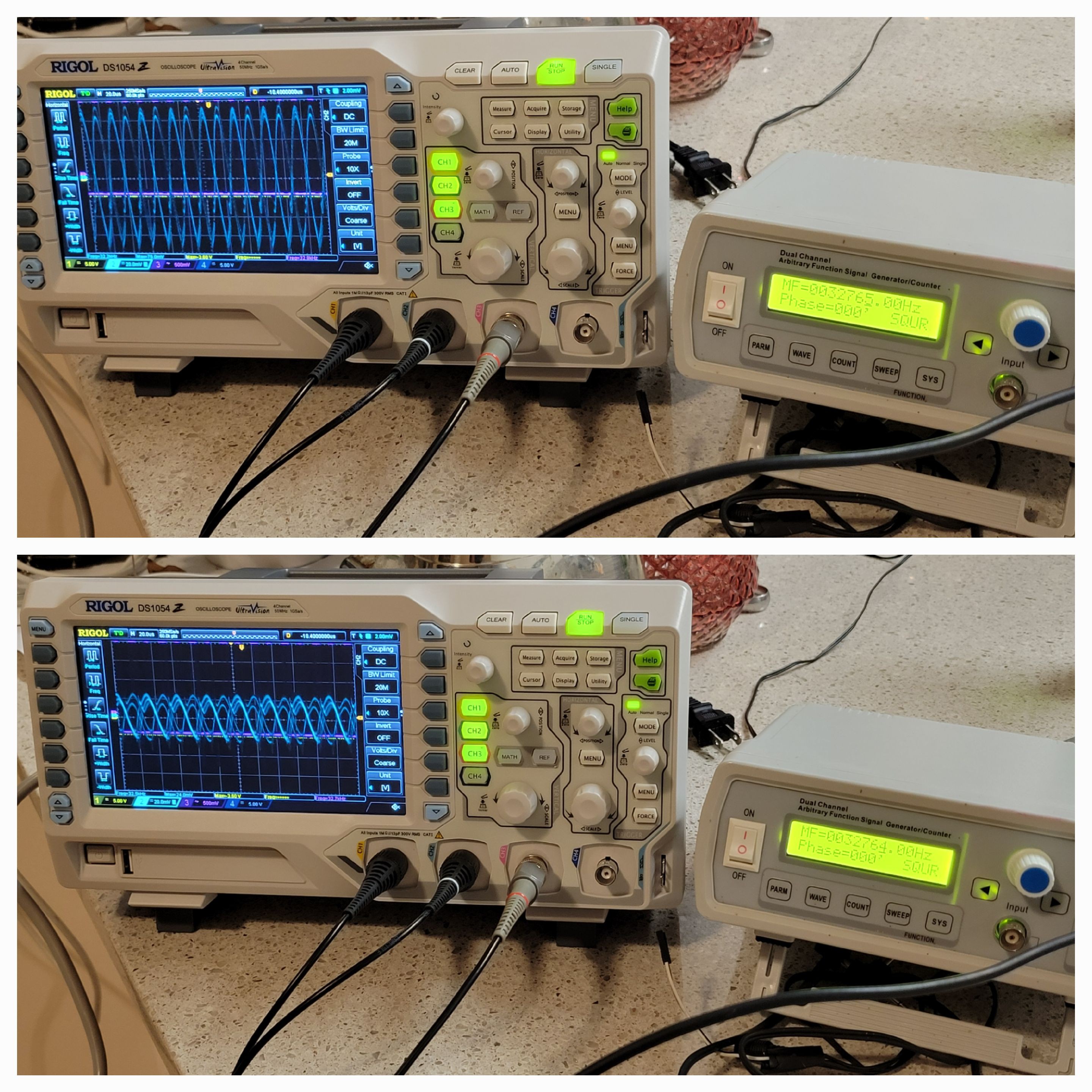
Also opened the quarz fork metallic case. Once opened frequency dropped by 5Hz and the peak was much lower as expected.
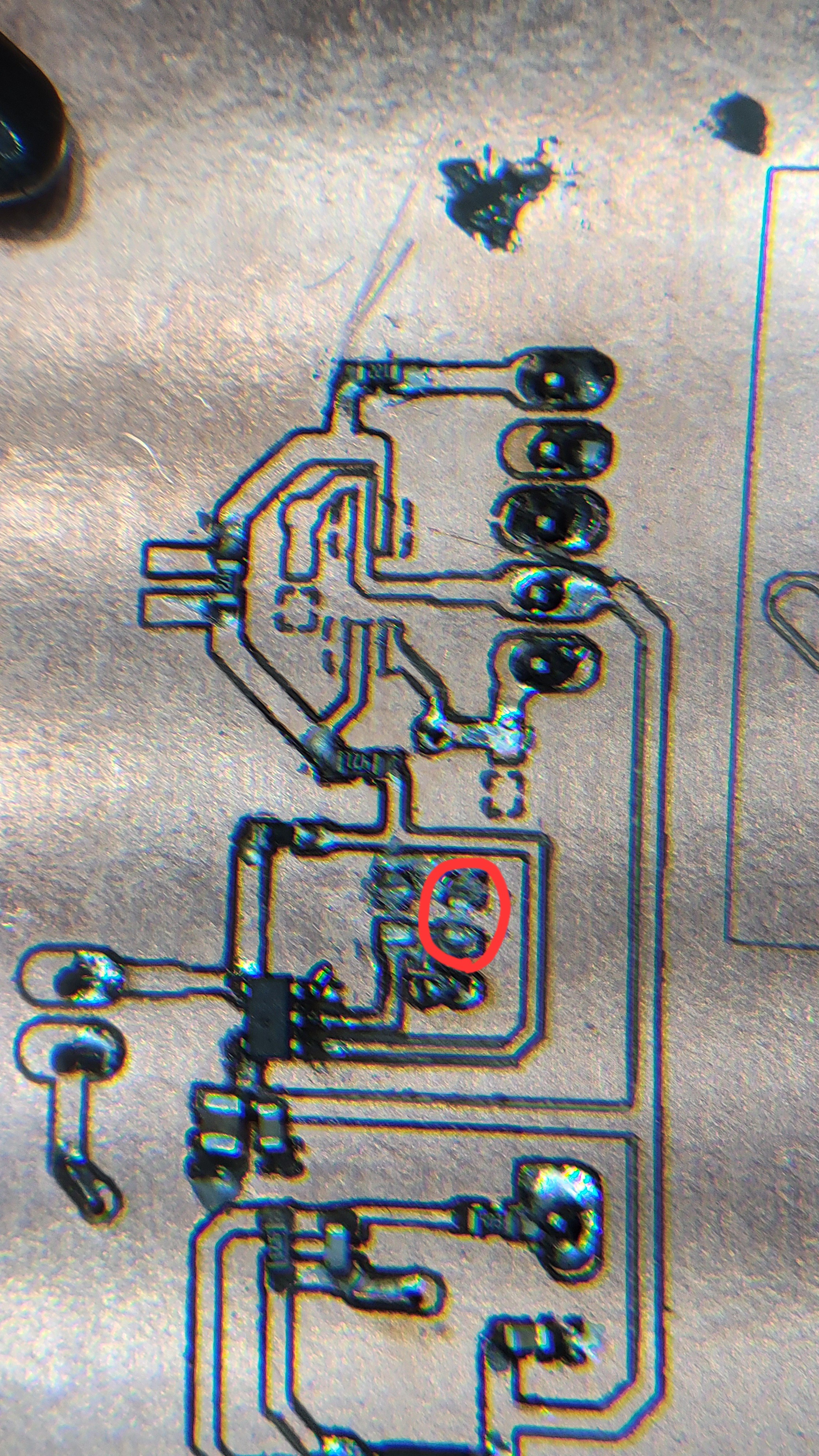
I had a problem with AD8675. Once I connected it the power would go down. First I thought it's my soldering problem. Then I thought it's faulty device. Nope, still short circuiting.
After long long time and numerous attempts, I found that the problem was what called NULL terminals. I was sure it should be connected to ground but it's something that else. I have disconnected them and left them floating, problem solved! Few, such a simple board and it took me so long to make it work. Although I still missing the capacitor compensation.
Discussions
Become a Hackaday.io Member
Create an account to leave a comment. Already have an account? Log In.